Vertex Standard VX-7200 Operating Manual
Apco p25/fm transceiver
Hide thumbs
Also See for VX-7200:
- Product manual (28 pages) ,
- Operating manual (21 pages) ,
- Operating manual (21 pages)

Related Manuals for Vertex Standard VX-7200


Summary of Contents for Vertex Standard VX-7200
- Page 1 APCO P25/FM T rAnsCeiver VX-7200 PerATing AnuAl Vertex Standard LMR, Inc. 4-6-8 Shibaura, Minato-ku, Tokyo 108-0023, Japan...
- Page 2 We’re glad you joined the Vertex Standard team. Call on us anytime, because com- munications is our business. Let us help you get your message across.
- Page 3 Vertex Standard VPL-1 (or FIF-12 ) Programming Cable and CE76 Software. The pages which follow will detail the many advanced features provided on the VX-7200 Series transceiver. After reading this manual, you may wish to consult with your Network Administrator regarding precise details of the configuration of this equipment for use in your application.
- Page 4 Increase the separation between the equipment and receiver. r Connect the equipment into an outlet on a circuit different from that to which the receiver is connected. r Consult the dealer or an experienced radio/TV technician for help. VX-7200 S erieS perating anual...
- Page 5 50 %, dans des configurations typiques de Push-to-Talk. Types d’antenne ayant un gain supérieur à 0 dBd sont strictement interdits pour une tilisation avec cet appareil. VX-7200 S erieS perating anual...
- Page 6 RF exposure for both workers and the general public. These recommended RF exposure levels include substantial margins of protection. All Vertex Standard two-way radios are designed, manufactured, and tested to en- sure they meet government-established RF exposure levels. In addition, manufac- turers also recommend specific operating instructions to users of two-way radios.
- Page 7 Compliance with RF Exposure Standard Your Vertex Standard two-way radio is designed and tested to comply with a num- ber of national and international standards and guidelines (listed below) regarding human exposure to radio frequency electromagnetic energy. This radio complies...
- Page 8 4.17 Feet ( 1.27 m ) IC RF Exposure Requirements When a mobile radio is used in conjunction with another co-located transmit- ter such as a Vehicular Repeater, it is the vehicle operator’s responsibility to VX-7200 S erieS perating anual...
-
Page 9: Mobile Antenna Installation Guidelines
RF energy exposure limits in the standards and guidelines listed above: The antenna should be mounted outside the building on the roof or a tower if at all possible. VX-7200 S erieS perating anual... -
Page 10: Compliance And Control Guidelines And Operating Instructions For Mobile Two-Way Radios Installed On Maritime Vessels
For additional installation information, see the guidelines for minimum Sepa- ration distances proved above in the RF Exposure Compliance and Control Guidelines and Operating Instructions section of this document. VX-7200 S erieS perating anual... -
Page 11: Mounting Bracket Installation
When installing the VX-7200 transceiver, make sure to plan the installation care- fully and leave additional room in the rear of the radio for cabling and accessory connections; in the front of the radio for access, controls, and cabling; and to the sides of the radio so that you may access and install the Hex Head Bolts. -
Page 12: Mobile Installation
Mobile Installation ower onnection VX-7200 transceiver operates only in negative ground electrical systems. Before starting the installation, make sure that the ground polarity of the vehicle is cor- rect. Accidentally reversing the polarity will not damage the transceiver, but will cause the cable fuses to blow. - Page 13 Trunk Lid Mount Should be located at the If can not meet the above distance at the trunk lid mount, above distance or more. the antenna must be placed in the center of the roof. VX-7200 S erieS perating anual...
-
Page 14: Base Station Installation
Operation of the VX-7200 transceiver from an AC line requires a power supply capable of providing at least 15 Amps continuously at 13.6 Volts DC. Please con- tact your dealer to select an optimal power supply that satisfy these requirements. - Page 15 VX-7200 S erieS perating anual...
-
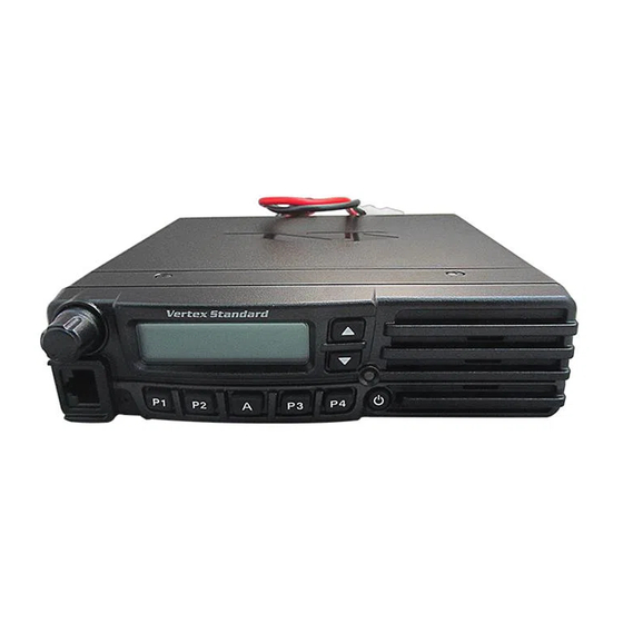
Page 16: Front Panel
Front Panel Important! - All buttons located on the Front Panel are Programmable Func- tion ( PF ) Buttons, configured according to your network requirements and programmed by your Vertex Standard dealer. The instructions below describe a typically-configured radio. ... - Page 17 Low Transmt Power Mode “ON” “Voice Message” received 12 Character Alpha-numeric Display Sub-LCD “Analog Transmission” is activated : Channel Group Number : Priority Channel : Home Channel : ARTS “In Range” : ARTS “Out of Range” VX-7200 S erieS perating anual...
-
Page 18: Rear Panel
An external loudspeaker may be connected to this 2-contact, 3.5-mm mini- phone jack. Caution: Do not connect either wire of this line to ground, and be certain that the speaker has adequate capability to handle the audio output (12 W) from the radio. VX-7200 S erieS perating anual... -
Page 19: Switching Power On/Off
If CTCSS or Digital Coded Squelch (DCS) Lockout has been programmed on a channel, the radio can transmit only when there is no carrier being received or when the carrier being received includes the correct CTCSS tone or DCS code. VX-7200 S erieS perating... -
Page 20: Automatic Time-Out Timer
Key Lock In order to prevent accidental frequency change or inadvertent transmission, vari- ous aspects of the VX-7200 ’s keys, and PTT switch, may be locked out. The pre- cise lockout configuration may be configured using the “User Set” (Menu) mode. -
Page 21: Operation
PerATiOn Programmable Function ( PF ) Buttons The VX-7200 Series includes seven Programmable Function ( PF ) Buttons. The PF button functions can be customized, via programming by your Vertex Standard dealer, to meet your communications/network requirements. Some features may require the purchase and installation of optional internal accessories. -
Page 22: Description Of Operating Functions
PF key for one second to delete the Current Memory channel from the Scanning. When you delete a Group or channel, “ - SCAN Skip - ” will appear on the LCD for one second after pressing the assigned PF key. To restore a partic- VX-7200 S erieS perating... -
Page 23: Advanced Operation
The scanner will search the two channels; it will pause each time it finds a channel on which someone is speaking. To stop Dual Watch: r Press the assigned PF key. r Operation will revert to the “Dual Watch Start” channel. VX-7200 S erieS perating anual... -
Page 24: F Ollow -M E S Can
Press the PF key again to return to “High Power” op- eration when in difficult terrain. When the radio’s transmitter is set to “Low Power” mode, the “ ” icon will be indicated on the display. VX-7200 S erieS perating anual... - Page 25 If so, the key may be used for one of the other Pre-Programmed Functions. MerGency The VX-7200 series include an “Emergency” feature which may be useful if you have someone monitoring on the same frequency as your transceiver’s channel. Press the assigned PF key to initiate an emergency call. For further details contact your Vertex Standard dealer.
- Page 26 The public address can be used even while scanning and receiving a call. EXT. ACC1 Press the assigned PF key to toggle output port on “1” “on” and “off.” eXt. Acc2 Press the assigned PF key to toggle output port on “2” “on” and “off.” VX-7200 S erieS perating anual...
- Page 27 M Press the assigned PF key to select the TX mode. Available selections are: TX Mixed: The VX-7200 transmits in the Analog Mode, when after receiving the analog signal. Meanwhile, the VX-7200 transmits in the Digi- tal Mode, when after receiving the digital signal.
-
Page 28: Arts (Auto Range Transpond System)
The Caller ID will appear on the LCD display when receiving Unit to Unit call (Paging). Caller ID: Tag information will appear when receiving the Source ID which listed at the Destination ID table on your radio, otherwise received Source ID will appear. VX-7200 S erieS perating anual... -
Page 29: User Set Mode
The VX-7200 Series includes a “User Set” (Menu) Mode which allows the user to define or configure various settings, such as Squelch, Display contrast, etc. To activate the “User Set” (Menu) Mode: r Press the PF key assigned to the “ SET ” function. - Page 30 Check with your VERTEX STANDARD Dealer for changes to this list. ArrAnTy OliCy Vertex Standard warrants, to the original purchaser only, its Vertex Standard manu- factured communications products against defects in materials and workmanship under normal use and service for a given period of time from the date of purchase.
- Page 31 Part 15.21: Changes or modifications to this device not expressly approved by Vertex Standard could void the user’s authorization to operate this device.
- Page 32 No portion of this manual may be reproduced without the per- mission of Vertex Standard LMR, Inc. Vertex Standard is a trademark of Vertex Standard LMR, Inc. All other trademarks are the property of their respective owners. ©2015 Vertex Standard LMR, Inc.