Table of Contents

Related Manuals for Miller Electric DB1712RDI25


Summary of Contents for Miller Electric DB1712RDI25
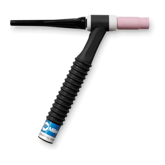
- Page 1 OM-1600 199 525E 1/2005 Processes TIG (GTAW) Welding Description TIG Torch Diamondback Series GTAW Torches DB1712R, DB1725R, DB1712RDI, DB1725RDI, DB1712RDI25, DB1725RDI25, DB17V12R, DB17V25R, DB17V12-2, And DB17V25-2 www.MillerWelds.com...
- Page 2 ISO 9001:2000 Quality System Standard. particular model are also provided. Miller Electric manufactures a full line of welders and welding related equipment. For information on other quality Miller products, contact your local Miller distributor to receive the latest full line catalog or individual catalog sheets.
-
Page 3: Table Of Contents
TABLE OF CONTENTS SECTION 1 −SAFETY PRECAUTIONS FOR GTAW TORCHES − READ BEFORE USING 1-1. Symbol Usage ............... . 1-2. - Page 4 Notes...
-
Page 5: Section 1 −Safety Precautions For Gtaw Torches − Read Before Using
SECTION 1 −SAFETY PRECAUTIONS FOR GTAW TORCHES − READ BEFORE USING 1-1. Symbol Usage Means Warning! Watch Out! There are possible hazards with this procedure! The possible hazards are shown in the adjoining symbols. This group of symbols means Warning! Watch Out! Possible ELECTRIC SHOCK and HOT PARTS hazards. Consult symbols and related instructions below for necessary actions to avoid the hazards. -
Page 6: Emf Information
Considerations About Welding And The Effects Of Low Frequency Electric And Magnetic Fields Welding current, as it flows through welding cables, will cause electro- magnetic fields. There has been and still is some concern about such fields. However, after examining more than 500 studies spanning 17 years of research, a special blue ribbon committee of the National Research Council concluded that: “The body of evidence, in the committee’... -
Page 7: Section 2 − Specifications
SECTION 2 − SPECIFICATIONS 2-1. Specifications Ampere Rating Cooling Method Tungsten Size Cable Options 12-1/2 ft (3.8 m) or 25 ft (7.6 m) One-Piece High−Flex Dimensions Length: 8 in (203 mm); Handle Diameter: 15/16 in (24 mm); Weight: 3.7 oz (105 g) 2-2. -
Page 8: Section 3 − Installation
SECTION 3 − INSTALLATION 3-1. Required Torch Parts And Torch Assembly Assembling Torch Parts Collet Body Heat Shield Backcap Insulator Collet O-Ring Backcap Torch Body Handle 3-2. International Style Connector Assembly Tools Needed: OM-1600 Page 4 10 One-Piece Power Cable 11 Power Cable Adapter 12 International Style Flow-Through Adapter... -
Page 9: Connecting Torch
3-3. Connecting Torch A. Connecting Torch With One-Piece Cable If applicable, install high-frequency unit. Torch Without Gas Valve Torch With Gas Valve Y Turn welding power source power before install- ing torch. Obtain the following hose: Gas Hose With 5/8-18 Right- Hand Fittings Connections: Regulator/Flowmeter... - Page 10 B. Connecting Torch With Two-Piece Cable If applicable, install high-frequency unit. Torch Without Gas Valve Torch With Gas Valve Tools Needed: 5/8, 7/8 in C. Connecting Torch With Flow-Through Type Connection If applicable, install high-frequency unit. Torch Without Gas Valve Ref.
-
Page 11: Section 4 − Maintenance & Troubleshooting
SECTION 4 − MAINTENANCE & TROUBLESHOOTING 4-1. Routine Maintenance 40 Hours Replace unreadable labels. Replace cracked parts 4-2. Troubleshooting NOTE Before using troubleshooting table, check selection and preparation of tungsten electrode according to Section 5. Trouble Arc will not start. High frequency present Check cable and work connections. - Page 12 Trouble Wandering arc Shield weld zone from drafts. Reduce gas flow rate. Select proper size and type of tungsten. Properly prepare tungsten according to Section 5. When using AC, check welding power source High Frequency control setting, and increase setting if nec- essary.
-
Page 13: Section 5 − Selecting And Preparing Tungsten Electrode For Dc Or Ac Welding
SECTION 5 − SELECTING AND PREPARING TUNGSTEN ELECTRODE FOR DC OR AC WELDING Y Whenever possible and practical, use DC weld output instead of AC weld output. 5-1. Selecting Tungsten Electrode ( Electrode Diameter DC − Argon − Electrode 2% Ceria (Orange Band), 1.5% Lan- thanum (Gray Band), Or 2% Thorium (Red Band) Alloy Tungstens .010”... -
Page 14: Preparing Tungsten Electrode For Welding
5-2. Preparing Tungsten Electrode For Welding Y Grinding the tungsten electrode produces dust and flying sparks which can cause injury and start fires. Use local exhaust (forced ventilation) at the grinder or wear an approved respirator. Read MSDS for safety infor- mation. -
Page 15: Torch Movement During Welding
6-2. Torch Movement During Welding Tungsten Without Filler Rod Welding direction Form pool Tilt torch Move torch to front of pool. Repeat process. Tungsten With Filler Rod Welding direction Form pool Tilt torch Add filler metal Remove rod Move torch to front of pool. -
Page 16: Section 7 − Parts List
SECTION 7 − PARTS LIST OM-1600 Page 12 22 or 23 Figure 7-1. Complete Torch Assembly 802 567-B... - Page 17 Item Stock Figure 7-1. Torch Models Without Gas Valve ..57Y02 ..BACK CAP, long ..57Y04 ..BACK CAP, button .
- Page 18 Item Stock Figure 7-1. Torch Models Without Gas Valve (continued) 194 722 ..ADAPTER, intl style flow through ..195 234 ..ADAPTER, intl style flow through 127 836 .
- Page 19 Item Stock Figure 7-1. Torch Models With Gas Valve ..57Y02 ..BACK CAP, long ..57Y04 ..BACK CAP, button .
- Page 20 Item Stock Figure 7-1. Torch Models With Gas Valve (continued) 127 836 ..PLUG, international style, tw lk insul male 129 527 ..PLUG, international style tw lk insul male .
- Page 21 Notes...
- Page 22 Notes...
- Page 23 Warranty Questions? Call LIMITED WARRANTY − Subject to the terms and conditions below, Miller Electric Mfg. Co., Appleton, Wisconsin, warrants to 1-800-4-A-MILLER its original retail purchaser that new Miller equipment sold after for your local the effective date of this limited warranty is free of defects in material and workmanship at the time it is shipped by Miller.
- Page 24 File a claim for loss or damage during shipment. For assistance in filing or settling claims, contact your distributor and/or equipment manufacturer’s Transportation Department. 2005 Miller Electric Mfg. Co. 1/05 Miller Electric Mfg. Co. An Illinois Tool Works Company 1635 West Spencer Street Appleton, WI 54914 USA International Headquarters−USA...