Table of Contents
Advertisement
Advertisement
Table of Contents
Troubleshooting

Related Manuals for Miller Electric OM-227 398D


Summary of Contents for Miller Electric OM-227 398D
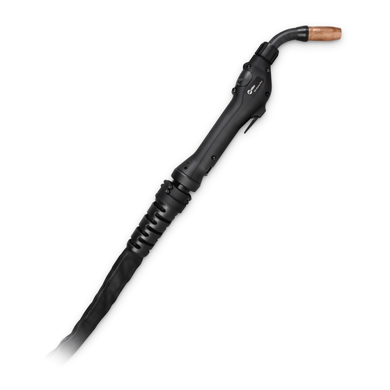
- Page 1 Visit our website at www.MillerWelds.com XR - Aluma-Pro (Air And Water-Cooled Guns) 300 Ampere (Air) Push-Pull Welding Gun 400 Ampere (Water) Push-Pull Welding Gun OM-227 398D 2007−12 Processes MIG (GMAW) Welding Description Semi-Automatic, Air/Water- Cooled, MIG (GMAW) Welding File: MIG (GMAW)
- Page 2 ISO 9001:2000 Quality System Standard. particular model are also provided. Miller Electric manufactures a full line of welders and welding related equipment. For information on other quality Miller products, contact your local Miller distributor to receive the latest full line catalog or individual specification sheets.
-
Page 3: Table Of Contents
TABLE OF CONTENTS SECTION 1 −SAFETY PRECAUTIONS FOR GMAW WELDING GUNS − READ BEFORE USING 1-1. Symbol Usage ............... . 1-2. - Page 4 Declaration of Conformity for European Community (CE) Products NOTE This information is provided for units with CE certification (see rating label on unit). Manufacturer: Miller Electric Mg. Co. 1635 W. Spencer St. Appleton, WI 54914 USA Phone: (920) 734-9821 European Contact Signature:...
-
Page 5: Section 1 −Safety Precautions For Gmaw Welding Guns − Read Before Using
SECTION 1 −SAFETY PRECAUTIONS FOR GMAW WELDING GUNS − READ BEFORE USING Protect yourself and others from injury — read and follow these precautions. 1-1. Symbol Usage DANGER! − Indicates a hazardous situation which, if not avoided, will result in death or serious injury. The possible hazards are shown in the adjoining symbols or explained in the text. -
Page 6: Emf Information
1-3. EMF Information Considerations About Welding And The Effects Of Low Frequency Electric And Magnetic Fields Welding current, as it flows through welding cables, will cause electro- magnetic fields. There has been and still is some concern about such fields. However, after examining more than 500 studies spanning 17 years of research, a special blue ribbon committee of the National Research Council concluded that: “The body of evidence, in the committee’... -
Page 7: Section 2 − Definitions
SECTION 2 − DEFINITIONS 2-1. Warning Label Definitions S-178 936 A. Warning! Watch Out! There are possible hazards as shown by the symbols. B. Drive rolls can injure fingers. C. Welding wire and drive parts are at welding voltage during operation −... -
Page 8: Manufacturer's Rating Label For Ce Products Only
2-2. Manufacturer’s Rating Label For CE Products Only 2-3. WEEE Label (For Products Sold Within The EU) 2-4. Symbols And Definitions Some symbols are found only on CE products. Amperes Degree Of Protection Press To Set Purge Burnback Time Primary Current Water (Coolant) Output OM-227 398 Page 4... -
Page 9: Section 3 − Introduction
SECTION 3 − INTRODUCTION 3-1. Specifications Model Welding Output Range XR-Aluma-Pro Gun 300 A at 100% Duty Cycle (Air Cooled) with 15, 25 or 35 ft (4.6 or 7.6 m) gun XR-Aluma-Pro Gun 400 A at 100% Duty Cycle (Water Cooled) with 15, 25 or 35 ft (4.6 or 7.6 m) gun When changing 1/16 in (1.6 mm) wire, kit 230708 must be installed. -
Page 10: Section 4 − Installation
SECTION 4 − INSTALLATION Be sure that contact tip, liner, and drive rolls are correct for wire size and type. See Parts List to change parts as needed. 4-1. Connections With A Constant Current (CC), Constant Voltage (CV) Or Constant Current/Constant Voltage (CC/CV) Welding Power Source Having A 14-Socket Re- ceptacle OM-227 398 Page 6... -
Page 11: Xr-Water-Cooled Gun Connections
4-2. XR-Water-Cooled Gun Connections Tools Needed: 9/16 in Left Side Turn on coolant supply before welding or gun will be dam- aged. Gun Control Cable Insert plug into Gun Control receptacle, and tighten threaded collar. Gun Connector Gun Securing Knob Gun Connector Block Loosen gun securing knob, and insert gun connector through Wire... -
Page 12: Millermatic 350P Water Cooled Gun Connections
4-3. Millermatic 350P Water Cooled Gun Connections Tools Needed: 9/16 in Turn on coolant supply before welding or gun will be damaged. Coolant Supply Millermatic 350P Gun Control Cable Insert plug into gun control receptacle and tighten threaded collar. OM-227 398 Page 8 Water In Hose Connect to coolant supply with supplied coupler and water hose (left-hand threads). -
Page 13: Threading Welding Wire For Aluma-Pro Gun And Millermatic 350P
4-4. Threading Welding Wire For Aluma-Pro Gun And Millermatic 350P Open pressure assembly. Push wire thru guides into gun; continue to hold wire. See Section 4-9 for threading welding wire through Aluma-Pro guns. IMPORTANT! For Aluminum Push−Pull welding. Thread hub tension nut loosely 218243−A 3/4 in Tighten to... -
Page 14: Threading Welding Wire Through Xr-Control Feeder
4-5. Threading Welding Wire Through XR-Control Feeder Tools Needed: 4-6. Adjusting Tension At Feeder Tools Needed: Open tension arm. Thread wire thru inlet guide, along drive roll groove, and into wire conduit. Close tension arm. Adjust tension as follows: grasp spool with one hand, press Jog switch, and turn thumb nut clockwise until motor stalls when Jog switch is pressed. -
Page 15: 10-Pin Plug Information
4-7. 10-Pin Plug Information Pin* 4-8. Opening Top Cover Of XR-Aluma-Pro Gun Pin Information Electrode sense lead Motor Common Trigger Motor 0 to +24 volts dc with respect to pin B Trigger Wire speed Ref. +9 volts dc Wire speed com Wire speed 0 to +9 volts dc with respect to pin H Gun sensing resistor with respect to pin H Not used... -
Page 16: Threading Welding Wire Through Gun
4-9. Threading Welding Wire Through Gun For XR-Aluma-Pro Gun: Welding wire is electrically live when gun trigger is used to jog wire. Turn OFF coolant supply before threading wire through gun.. Cut off wire. Close and latch wire feeder door. Tools Needed: OM-227 398 Page 12 Refer to Section 4-4 for instructions on feeding... -
Page 17: Section 5 − Operation
SECTION 5 − OPERATION 5-1. Gun Controls 5-2. Gun Pressure Roll Tension Setting Tools Needed: Trigger Press trigger to energize welding power source contactor applicable), start shielding gas flow, and begin wire feed. Switches inside the wire feeder can be set to provide timed shielding gas preflow and postflow when trigger is pressed and released. -
Page 18: Shielding Gas
5-3. Shielding Gas 5-4. Coolant Supply For Water-Cooled Models Only GTAW Or Where Application HF* Is Used MILLER Low Conductivity Coolant No. 043 810** Coolant *HF: High Frequency Current **MILLER coolants protect to -37 F (-38 C) and resist algae growth. OM-227 398 Page 14 GMAW Or Where Coolant Contacts Aluminum Parts Or... -
Page 19: Gun Drive Assembly Maintenance For An Xr-Aluma-Pro Gun
5-5. Gun Drive Assembly Maintenance For An XR-Aluma-Pro Gun Tools Needed: 5/16 in Lever Arm Using lever arm open pressure roll with bearing as shown. Retract wire onto spool. Drive Roll Use wire brush to clean drive roll. Install drive roll with hex opening down toward shaft hex, and secure with screw. -
Page 20: Replacing Head Tube Liner In Xr-Aluma-Pro Guns
5-6. Replacing Head Tube Liner In XR-Aluma-Pro Guns 5-7. Changing Gun Contact Tip OM-227 398 Page 16 Tapered end Turn OFF coolant supply before removing head tube water-cooled gun. The standard head tube liner will ac- commodate wire diameters from .030-.035 wire size. -
Page 21: Replacing The Gun Liner On Xr-Aluma-Pro Guns
5-8. Replacing The Gun Liner On XR-Aluma-Pro Guns Refer To Instructions Below. Remove Old Liner (Item 2) From Gun End Install New Liner (Item 2) Into Gun End Gently pry open slots to remove wire collet guide. Turn Off welding power source and wire feeder. -
Page 22: Section 6 − Maintenance & Troubleshooting
SECTION 6 − MAINTENANCE & TROUBLESHOOTING 6-1. Routine Maintenance For Aluminum Push/Pull Guns n = Check ~ = Clean Daily n~ Head Tube Liner and Drive Casting (see Section 5-6) Weekly n~ Drive Roll Every Spool of Wire n~ Nozzle / Contact Tip ~ Gun Casing Every Months... -
Page 23: Cleaning The Gun Liner On Xr-Aluma-Pro Guns
6-2. Cleaning The Gun Liner On XR-Aluma-Pro Guns Turn Off welding power source and wire feeder. Lay gun cable out straight. Leather Cover Remove leather cover to access liner as- sembly. Liner Guide Reducer Liner Lock Allen Head Screw Power Pin Air Nozzle Gun End Power Pin End... -
Page 24: Troubleshooting Table
6-3. Troubleshooting Table Trouble Reset circuit breaker in feeder/control box. See feeder/control owner’s manual. No wire feed at gun, feeder not operat- ing. Check motor or brake solenoid. ing Check motor or brake solenoid Replace trigger-switch and test operation. Check trigger-switch wires for continuity. No wire feed at gun, feeder operating Reset circuit breaker in feeder/control box and check for short in motor leads. -
Page 25: Section 7 − Electrical Diagrams
SECTION 7 − ELECTRICAL DIAGRAMS 228 669-B Figure 7-1. Circuit Diagram For XR-Aluma-Pro Gun Notes OM-227 398 Page 21... -
Page 26: Section 8 − Parts List
SECTION 8 − PARTS LIST Hardware is common and not available unless listed. Figure 8-1. Exploded View Of XR-A Aluma-Pro Gun OM-227 398 Page 22... - Page 27 Item Part Figure 8-1. Exploded View Of XR-A Aluma-Pro Gun ... . . 231 517 Kit, Head Tube Assy (Water) Long ... . . 231 519 Kit, Head Tube Assy (Air) Short .
- Page 28 Item Part ... . . 229 887 Liner, Replacement 15 Ft ... . . 229 891 Liner, Replacement 25 Ft .
- Page 29 Hardware is common and not available unless listed. Figure 8-2. (Water) Head Tube Assembly Of Aluma-Pro Gun Item Part Figure 8-2. (Water) Head Tube Assembly Of Aluma-Pro Gun (Figure 8-1 Item 1 ....231 517 Kit, Head Tube Assy Water Aluma−Pro (Long) (Includes) .
- Page 30 Hardware is common and not available unless listed. Figure 8-3. (Air) Head Tube Assembly Of Aluma-Pro Gun Item Part Figure 8-3. (Air) Head Tube Assembly Of Aluma-Pro Gun (Figure 8-1 Item 2) ....231 518 Kit, Head Tube Assy Air (Long) (Includes) .
-
Page 31: Section 9 − Parts List Including Consumables
SECTION 9 − PARTS LIST INCLUDING CONSUMABLES Item Number Item Part 9-1. Consumables Flowchart Table 9-1. Nozzles ... 199 610 Nozzle, Screw On Brass 1/2 in Orifice .. - Page 32 Table 9-2. Heavy Duty FasTiptContact Tips* ... 206 185 .030 in (0.8 mm) ... 206 186 .035 in (0.9 mm) .
- Page 33 Notes SOCKET/WRENCH SELECTION TABLE (U.S. STANDARD) Specifications Socket or Wrench Size Bolt Decimal Bolt Diameter Equivalent 1/4 in .250 in 3/8 in 5/16 in .3125 in 1/2 in 3/8 in .375 in 9/16 in 7/16 in .4375 in 5/8 in 1/2 in .500 in 3/4 in...
- Page 34 Notes MATERIAL THICKNESS REFERENCE CHART 24 Gauge (.025 in) 22 Gauge (.031 in) 20 Gauge (.037 in) 18 Gauge (.050 in) 16 Gauge (.063 in) 14 Gauge (.078 in) 1/8 in (.125 in) 3/16 in (.188 in) 1/4 in (.25 in) 5/16 in (.313 in) 3/8 in (.375 in) 1/2 in (.5 in)
- Page 35 Warranty Questions? LIMITED WARRANTY − Subject to the terms and conditions Call below, Miller Electric Mfg. Co., Appleton, Wisconsin, warrants to 1-800-4-A-MILLER its original retail purchaser that new Miller equipment sold after the effective date of this limited warranty is free of defects in for your local material and workmanship at the time it is shipped by Miller.
-
Page 36: Options And Accessories
File a claim for loss or damage during shipment. For assistance in filing or settling claims, contact your distributor and/or equipment manufacturer’s Transportation Department. 2007 Miller Electric Mfg. Co. 2007−01 Miller Electric Mfg. Co. An Illinois Tool Works Company 1635 West Spencer Street Appleton, WI 54914 USA International Headquarters−USA...