
Related Manuals for Miller Electric 185


Summary of Contents for Miller Electric 185
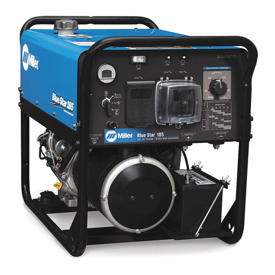
- Page 1 OM-4415 209 416F 2007−05 Processes Stick (SMAW) Welding Description Engine Driven Welding Generator Blue Star 185 Blue Star 185 DX File: Engine Drive Visit our website at www.MillerWelds.com...
- Page 2 ISO 9001:2000 Quality System Standard. particular model are also provided. Miller Electric manufactures a full line of welders and welding related equipment. For information on other quality Miller products, contact your local Miller distributor to receive the latest full line catalog or individual specification sheets.
-
Page 3: Table Of Contents
TABLE OF CONTENTS SECTION 1 − SAFETY PRECAUTIONS − READ BEFORE USING 1-1. Symbol Usage ............... 1-2. -
Page 5: Section 1 − Safety Precautions − Read Before Using
SECTION 1 − SAFETY PRECAUTIONS − READ BEFORE USING Protect yourself and others from injury — read and follow these precautions. 1-1. Symbol Usage DANGER! − Indicates a hazardous situation which, if not avoided, will result in death or serious injury. The possible hazards are shown in the adjoining symbols or explained in the text. - Page 6 FUMES AND GASES can be hazardous. Welding produces fumes and gases. Breathing these fumes and gases can be hazardous to your health. D Keep your head out of the fumes. Do not breathe the fumes. D If inside, ventilate the area and/or use local forced ventilation at the arc to remove welding fumes and gases.
-
Page 7: Engine Hazards
1-3. Engine Hazards BATTERY EXPLOSION can BLIND. D Always wear a face shield, rubber gloves, and protective clothing when working on a battery. D Stop engine before disconnecting or connect- ing battery cables or servicing battery. D Do not allow tools to cause sparks when working on a battery. D Do not use welder to charge batteries or jump start vehicles. -
Page 8: Additional Symbols For Installation, Operation, And Maintenance
HOT METAL from air arc cutting and gouging can cause fire or explosion. D Do not cut or gouge near flammables. D Watch for fire; keep extinguisher nearby. HOT PARTS can cause burns and injury. D Do not touch hot compressor or air system parts. -
Page 9: California Proposition 65 Warnings
H.F. RADIATION can cause interference. D High-frequency (H.F.) can interfere with radio navigation, safety services, computers, and communications equipment. D Have only qualified persons familiar with electronic equipment perform this installation. D The user is responsible for having a qualified electrician promptly correct any interference problem resulting from the installation. -
Page 10: Section 2 − Consignes De Sécurité − Lire Avant Utilisation
SECTION 2 CONSIGNES DE SÉCURITÉ − LIRE AVANT − Se protéger, ainsi que toute autre personne travaillant sur les lieux, contre les étincelles et le métal chaud. 2-1. Signification des symboles DANGER! − Indique une situation dangereuse qui si on l’évite pas peut donner la mort ou des blessures graves. - Page 11 Une tension DC importante subsiste à l’intérieur des onduleurs après avoir coupé l’alimentation. D Couper l’alimentation du poste et décharger les condensateurs d’entrée comme indiqué dans la Section Maintenance avant de toucher des composants. DES PIÈCES CHAUDES peuvent provoquer des brûlures graves. D Ne pas toucher à...
-
Page 12: Dangers Existant En Relation Avec Le Moteur
D Suivre les recommandations dans OSHA 1910.252(a)(2)(iv) et NFPA 51B pour les travaux à chaud et avoir de la surveillance et un extincteur à proximité. LE BRUIT peut affecter l’ouïe. Le bruit des processus et des équipements peut affec l’ouïe. D Porter des protections approuvés pour les ore les si le niveau sonore est trop élevé. -
Page 13: Dangers Liés À L'air Comprimé
D Dévisser le bouchon légèrement et laisser la vapeur s’échapper avant d’enlever le bouchon. L’utilisation d’un groupe autonome à l’intérieur PEUT VOUS TUER EN QUELQUES MINUTES. D Les fumées d’un groupe autonome contient du monoxyde de carbone. C’est un poison invisi- ble et inodore. - Page 14 LE SURCHAUFFEMENT peut endom- mager le moteur électrique. D Arrêter ou déconnecter l’équipement avant de démarrer ou d’arrêter le moteur. D Ne pas laisser tourner le moteur trop lentement sous risque d’en- dommager le moteur électrique à cause d’une tension et d’une fré- quence trop faibles.
-
Page 15: Proposition Californienne 65 Avertissements
2-6. Proposition californienne 65 Avertissements Les équipements de soudage et de coupage produisent des fumées et des gaz qui contiennent des produits chimiques dont l’État de Californie reconnaît qu’ils provoquent des mal- formations congénitales et, dans certains cas, des cancers. (Code de santé... -
Page 16: Section 3 − Definitions
4-1. Weld, Power, And Engine Specifications Weld Welding Rated Output Mode Welding Output Range 185 A, 25 V, 20% Duty Cycle 130 A, 25 V, CC/DC 55 − 185 A 60% Duty Cycle 100 A, 25 V 100% Duty Cycle OM-4415 Page 12 Complete Parts List available at www.MillerWelds.com... -
Page 17: Dimensions, Weights, And Operating Angles
Optional Lifting Eye Weight Rating 430 lb (195 kg) 4-3. Duty Cycle 100% Duty Cycle at 100 Amperes CC/DC 2 Minutes Welding 20% Duty Cycle at 185 Amperes CC/DC Complete Parts List available at www.MillerWelds.com Holes Engine End 803 403 Continuous Welding... -
Page 18: Volt-Ampere Curves
4-4. Volt-Ampere Curves A. Standard Model (Honda Engine) B. DX Model (Kohler Engine) OM-4415 Page 14 Complete Parts List available at www.MillerWelds.com AMPERES AMPERES The volt-ampere curve shows the minimum and maximum voltage and amperage output capabilities of the welding generator. Curves of all other settings fall between the curves shown. -
Page 19: Fuel Consumption Curves
4-5. Fuel Consumption Curves A. Weld Output Standard Model (Honda Engine) 1.00 0.80 0.60 0.40 0.20 0.00 75 100 125 150 175 200 DC Weld Amperes At Rated Duty Cycle 1.20 1.00 0.80 0.60 0.40 0.20 0.00 Aux Power kW At 100% Duty Cycle 1.00 0.80 0.60... -
Page 20: Generator Power Curves
4-6. Generator Power Curves A. Power Output Standard Model (Honda Engine) B. Power Output DX Model (Kohler Engine) OM-4415 Page 16 Complete Parts List available at www.MillerWelds.com 240 VOLT AMPERES 240 VOLT AMPERES The ac generator power curves show the generator power available in amperes at the receptacles. -
Page 21: Section 5 − Installation
SECTION 5 − INSTALLATION 5-1. Installing Welding Generator Movement Location Always securely fasten welding generator onto transport vehicle or trailer and comply with all DOT and other applicable codes GND/PE Complete Parts List available at www.MillerWelds.com Airflow Clearance 18 in (460 mm) 18 in (460 mm) -
Page 22: Grounding Generator When Supplying Building Systems
5-2. Grounding Generator When Supplying Building Systems 5-3. Engine Prestart Checks − Standard Model 1/2 in (13 mm) Gasoline OM-4415 Page 18 Complete Parts List available at www.MillerWelds.com GND/PE Full Full Ground generator to system earth ground if supplying power to a premises (home, shop, farm) wiring system. -
Page 23: Engine Prestart Checks − Dx Model
5-4. Engine Prestart Checks − DX Model 1/2 in (13 mm) Full Gasoline Fuel valve is shown in the open position. Always close fuel valve after stopping unit. Moving unit with fuel valve open may cause carburetor flooding and make starting difficult. -
Page 24: Connecting To Weld Output Terminals
5-6. Connecting To Weld Output Terminals Do not place anything between weld cable terminal and copper bar. Correct Installation 5-7. Selecting Weld Cable Sizes* Welding Amperes Weld Output Weld O tp t Terminals Stop engine before connecting to weld connecting to weld output terminals. - Page 25 Complete Parts List available at www.MillerWelds.com Notes OM-4415 Page 21...
-
Page 26: Section 6 − Operating The Welding Generator
Complete Parts List available at www.MillerWelds.com SECTION 6 − OPERATING THE WELDING GENERATOR 6-1. Controls (Standard Models) (See Section 6-2) 803 597−B / 218 611−B OM-4415 Page 22... -
Page 27: Description Of Controls (Standard Models) (See Section 6-1)
6-2. Description Of Controls (Standard Models) (See Section 6-1) Engine Switch Use switch to control ignition circuit. Turn switch to On position when starting engine. Turn switch to Off position to stop engine. En- gine cannot be started with switch in the Off position. -
Page 28: Controls (Dx Models) (See Section 6-4)
Complete Parts List available at www.MillerWelds.com 6-3. Controls (DX Models) (See Section 6-4) 803 596−B / 803 595−B / 218 611−B OM-4415 Page 24... -
Page 29: Description Of Controls (Dx Models) (See Section 6-3)
6-4. Description Of Controls (DX Models) (See Section 6-3) Engine Switch Use switch to control ignition circuit. Turn switch to Start position for electric start. Turn switch to On position to start engine using starter handle (recoil). Turn switch to Off posi- tion to stop engine. -
Page 30: Section 7 − Operating Auxiliary Equipment
SECTION 7 − OPERATING AUXILIARY EQUIPMENT 7-1. Generator Power Panel Receptacles If unit does not have GFCI recep- tacles, use GFCI-protected exten- sion cord. Generator power decreases as weld current increases. Set Weld Output control to maximum for full generator power output at AC receptacles. -
Page 31: Section 8 − Maintenance
SECTION 8 − MAINTENANCE Follow the storage procedure in the engine owner’s manual if the unit will not be used for an extended period. 8-1. Routine Maintenance n = Check Z = Change * To be done by Factory Authorized Service Agent Every Hours n Fuel Level... -
Page 32: Servicing Air Cleaner
8-2. Servicing Air Cleaner OM-4415 Page 28 Complete Parts List available at www.MillerWelds.com Standard Model Shown Stop engine. NOTICE − Do not run engine with- out air cleaner or with dirty element. Precleaner Paper Element Do not wash paper element or clean with compressed air. -
Page 33: Adjusting Engine Speed (Honda-Powered Units)
8-3. Adjusting Engine Speed (Honda-Powered Units) Tools Needed: 1/4, 3/8 in Complete Parts List available at www.MillerWelds.com 1400 150 rpm 3750 30 rpm (62 Hz) After tuning engine, check engine speeds. See table for proper no load speeds. If necessary, adjust speeds as follows: Start engine and run until warm. -
Page 34: Adjusting Engine Speed (Kohler−Powered Units)
8-4. Adjusting Engine Speed (Kohler−Powered Units) Tools Needed: OM-4415 Page 30 Complete Parts List available at www.MillerWelds.com After tuning engine, check engine speed. See table for proper no load speed. If necessary, adjust speed as follows: 2500 100 rpm (42 Hz) Start engine and run until warm. -
Page 35: Section 9 − Troubleshooting
SECTION 9 − TROUBLESHOOTING 9-1. Troubleshooting A. Welding Trouble No weld output or generator power out- Be sure all equipment is disconnected from receptacles when starting unit. put at ac receptacles. Have Factory Authorized Service Agent check brushes, slip rings, rotor, stator, integrated rectifier SR2, and Weld Output control R1. - Page 36 Trouble Low output at generator power ac Check Weld Output control setting. receptacles. Check engine speed, and adjust if necessary (see Section 8-3 or 8-4). Open circuit voltage is reduced as engine speed drops. Erratic output at generator power ac Check fuel level.
-
Page 37: Section 10 − Parts List
SECTION 10 − PARTS LIST 10-1. Recommended Spare Parts Dia. Part Mkgs....220305 Tune−up & Filter Kit, Honda (includes) ....190108 . -
Page 38: Section 11 − Electrical Diagrams
SECTION 11 − ELECTRICAL DIAGRAMS 226 737-A Figure 11-1. Circuit Diagram For Standard Models OM-4415 Page 34... - Page 39 226 738-A Figure 11-2. Circuit Diagram for DX Models OM-4415 Page 35...
-
Page 40: Section 12 − Generator Power Guidelines
SECTION 12 − GENERATOR POWER GUIDELINES The views in this section are intended to be representative of all engine-driven welding generators. Your unit may differ from those shown. 12-1. Selecting Equipment 12-2. Grounding Generator To Truck Or Trailer Frame GND/PE OM-4415 Page 36 Generator Power Receptacles −... -
Page 41: Grounding When Supplying Building Systems
12-3. Grounding When Supplying Building Systems 12-4. How Much Power Does Equipment Require? GND/PE VOLTS 115 AMPS Equipment Grounding Terminal Grounding Cable Use #10 AWG or larger insulated copper wire. Ground Device Use ground device as stated in electrical codes. Ground generator to system earth ground if supplying power to a premises (home,... - Page 42 12-5. Approximate Power Requirements For Industrial Motors Industrial Motors Split Phase Capacitor Start-Induction Run Capacitor Start-Capacitor Run Fan Duty 12-6. Approximate Power Requirements For Farm/Home Equipment Farm/Home Equipment Stock Tank De-Icer Grain Cleaner Portable Conveyor Grain Elevator Milk Cooler Milker (Vacuum Pump) FARM DUTY MOTORS Std.
- Page 43 12-7. Approximate Power Requirements For Contractor Equipment Contractor Hand Drill Circular Saw Table Saw Band Saw Bench Grinder Air Compressor Electric Chain Saw Electric Trimmer Electric Cultivator Elec. Hedge Trimmer Flood Lights Submersible Pump Centrifugal Pump Floor Polisher High Pressure Washer 55 gal Drum Mixer Wet &...
- Page 44 12-8. Power Required To Start Motor Motor Start Code KVA/HP 12-9. How Much Power Can Generator Supply? OM-4415 Page 40 Single-Phase Induction Motor Starting Requirements 10.0 AC MOTOR VOLTS AMPS CODE PHASE 11.2 12.5 Motor Start Code Running Amperage Motor HP Motor Voltage To find starting amperage: Step 1: Find code and use table to...
- Page 45 12-10. Typical Connections To Supply Standby Power Utility Electrical Transfer Switch Service Essential Loads Fused Welding Disconnect Generator Switch Output (If Required) Have only qualified persons perform these connections according to all applicable codes and safety practices. Properly install and ground this equipment according to its Owner’s Manual and na- tional, state, and local codes.
- Page 46 12-11. Selecting Extension Cord (Use Shortest Cord Possible) Cord Lengths for 120 Volt Loads If unit does not have GFCI receptacles, use GFCI-protected extension cord. Current Load (Watts) (Amperes) 1200 1800 2400 3000 3600 4200 4800 5400 6000 *Conductor size is based on maximum 2% voltage drop Cord Lengths for 240 Volt Loads If unit does not have GFCI receptacles, use GFCI-protected extension cord.
-
Page 47: Section 13 − Stick Welding (Smaw) Guidelines
SECTION 13 − STICK WELDING (SMAW) GUIDELINES 13-1. Stick Welding Procedure Tools Needed: Weld current starts when elec- trode touches workpiece. Weld current can damage elec- tronic parts in vehicles. Discon- nect both battery cables before welding on a vehicle. Place work clamp as close to the weld as possible. -
Page 48: Electrode And Amperage Selection Chart
13-2. Electrode and Amperage Selection Chart 3/32 6010 5/32 & 3/16 6011 7/32 1/16 5/64 3/32 6013 5/32 3/16 7/32 3/32 5/32 7014 3/16 7/32 3/32 5/32 7018 3/16 7/32 3/32 5/32 7024 3/16 7/32 3/32 Ni-Cl 5/32 3/16 3/32 308L 5/32 13-3. -
Page 49: Positioning Electrode Holder
13-5. Positioning Electrode Holder End View of Work Angle End View of Work Angle 13-6. Poor Weld Bead Characteristics 13-7. Good Weld Bead Characteristics 10 -30 Side View of Electrode Angle GROOVE WELDS 10 -30 Side View of Electrode Angle FILLET WELDS S-0060 Large Spatter Deposits... -
Page 50: Conditions That Affect Weld Bead Shape
13-8. Conditions That Affect Weld Bead Shape Weld bead shape is affected by electrode angle, arc length, travel speed, and thickness of base metal. Angle Too Small Too Short Slow 13-9. Electrode Movement During Welding Normally, a single stringer bead is satisfactory for most narrow groove weld joints; however, for wide groove weld joints or bridging across gaps, a weave bead or multiple stringer beads work better. -
Page 51: Butt Joints
13-10. Butt Joints 13-11. Lap Joint Or Less Single-Layer Fillet Weld 13-12. Tee Joint 1/16 in (1.6 mm) Or Less Multi-Layer Fillet Weld Or Less Tack Welds Prevent edges of joint from drawing together ahead of electrode by tack welding the materials in position be- fore final weld. -
Page 52: Weld Test
13-13. Weld Test 2 To 3 in (51-76 mm) 1/4 in (6.4 mm) 13-14. Troubleshooting − Porosity Possible Causes Arc length too long. Damp electrode. Workpiece dirty. 13-15. Troubleshooting − Excessive Spatter Possible Causes Amperage too high for electrode. Arc length too long or voltage too high. OM-4415 Page 48 2 To 3 in (51-76 mm) -
Page 53: Troubleshooting − Incomplete Fusion
13-16. Troubleshooting − Incomplete Fusion Possible Causes Insufficient heat input. Improper welding technique. Workpiece dirty. 13-17. Troubleshooting − Lack Of Penetration Lack of Penetration Good Penetration Possible Causes Improper joint preparation. Improper weld technique. Insufficient heat input. 13-18. Troubleshooting − Excessive Penetration Excessive Penetration Good Penetration Possible Causes... -
Page 54: Troubleshooting − Burn-Through
13-19. Troubleshooting − Burn-Through Possible Causes Excessive heat input. 13-20. Troubleshooting − Waviness Of Bead Possible Causes Unsteady hand. Use two hands. Practice technique. 13-21. Troubleshooting − Distortion Base metal moves in the direction of the weld bead. Possible Causes Excessive heat input. - Page 55 Warranty Questions? LIMITED WARRANTY − Subject to the terms and conditions Call below, Miller Electric Mfg. Co., Appleton, Wisconsin, warrants to 1-800-4-A-MILLER its original retail purchaser that new Miller equipment sold after the effective date of this limited warranty is free of defects in for your local material and workmanship at the time it is shipped by Miller.
- Page 56 File a claim for loss or damage during shipment. For assistance in filing or settling claims, contact your distributor and/or equipment manufacturer’s Transportation Department. 2007 Miller Electric Mfg. Co. 2007−01 Miller Electric Mfg. Co. An Illinois Tool Works Company 1635 West Spencer Street Appleton, WI 54914 USA International Headquarters−USA...