Planet nvr-810 User Manual
8/16-channel
Hide thumbs
Also See for nvr-810:
- User manual (63 pages) ,
- User manual (72 pages) ,
- Quick installation manual (16 pages)

Related Manuals for Planet nvr-810


Summary of Contents for Planet nvr-810
- Page 1 User’s Manual 8/16-Channel Network Video Recorder NVR-810 / NVR-1610 www.PLANET.com.tw...
- Page 2 PLANET. PLANET makes no rep resentations or warrantie s, either expressed or impli ed, with respe ct to the contents hereof and specifically disclaims any warranties, merchantability or fitness for any p articular purpose.
- Page 3 DC-plug for the device if this device is not intended to be active. Revision User’s Manual for PLANET 8/16-ch Network Video Recorder Model: NVR-810 / NVR-1610 Rev: 1.0 (April, 2012) Part No. EM-NVR810(V3)/ NVR1610(V3)_v1.0...
-
Page 4: Table Of Contents
Table of Contents 1. Product Description .................... 5 1.1 Product Features ..................5 1.2 System Requirements ................7 1.3 Packet Content ................... 7 1.4 Specification ....................8 1.5 Front Panel....................10 1.6 LEDs Definition ..................10 1.7 I/O Ports......................11 2. Install Hard Disk....................14 3. - Page 5 6.4.1 General Settings ................62 6.4.2 Schedule Recording............... 64 6.5 System Options ..................65 6.5.1 Device Information ................. 65 6.5.2 Logs and Reports ................65 6.5.3 Maintenance..................66 6.5.4 DO Status ..................68 6.5.5 Disk Status ..................68 6.5.6 USB Backup ..................69 6.5.7 UPS Configuration................
-
Page 7: Product Description
Manual or Schedule Recording of 16 IP Cameras simultaneously (8 IP Camera by NVR-810) Management: Up to 32 / 16 NVR, max. 128 (NVR-810) / 256 (NVR-1610) channels with the management software Video recycle function makes the video recording in 7/24... - Page 8 Supports external UPS (USB)
-
Page 9: System Requirements
1.2 System Requirements The following are minimum system requirements for the system to operate Network Video Recorder (NVR): Operating System Microsoft® Windows® 2000 Pr ofessional, Windows® XP Professional ,Windows® Server 2003 / 2008 or Windows® 7 Browser Microsoft Internet Explorer 7 or above Minimum Intel®... -
Page 10: Specification
1.4 Specification Product NVR-810 NVR-1610 Video Compression MJPEG/MPEG-4/H.264 Resolution 5 MP/HD/MegaPixel/FD1/CIF/QCIF 240 fps (1920x1080, Max. Frame Rate 480 fps (1280X1024, H.264) H.264) Display Mode Live View/Playback/Full Screen Virtual PTZ Panel/Auto Pan/Preset Point/ PTZ Support Preset Sequence/Digital PTZ Sequence All Sequence Mode... - Page 11 Operating Temperature 0~45 Degree C Storage Temperature -40~70 Degree C Humidity 0~90% (non-condition) Weight 2.89 kg Dimension (W x D x H) 170 x 215 x 125 mm...
-
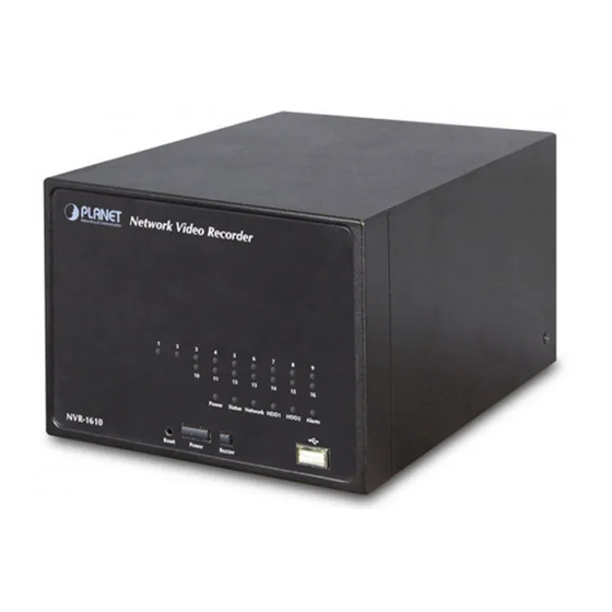
Page 12: Front Panel
1.5 Front Panel NVR-810 NVR-1610 1.6 LEDs Definition... -
Page 13: I/O Ports
Solid green when the hard disk is mounted Green and being accessed Solid red for disk fail HDD x 2 Solid amber when disk is recording Amber Blinking when recycling Amber Solid amber for activity on a 1G bps network. Network Solid green for activity on a 10/100 Mbps Green... - Page 14 Signal DC IN Alarm Input 1 Alarm Input 2 Alarm Input 3 Alarm Input 4 Alarm Input 5...
- Page 15 Alarm Input 6 Alarm Input 7 Alarm Input 8 Alarm Out 1 Alarm Out 2 Alarm Out 3 Alarm Out 4 RS-485+ RS-485-...
-
Page 16: Install Hard Disk
2. Install Hard Disk 1. Removing the screws on the side. 2. Push the top housing forward, then lift it up. 3. Removing the screws on the HDD Tray left and right side. - Page 17 4. Insert the HDD to HDD tray. Please push the HDD until the SATA connect is connected properly, and lock the HDD Screw on left and right side. 5. If there is a second HDD, please repeat the step 4 to install it. •...
-
Page 18: Connect To The Nvr
3. Connect to the NVR There are various ways you can connect to the NVR and below are the suggested methods for different network setup: The NVR is placed in a network with a DHCP serv er: Connect to the NVR by using “Device Search”... - Page 19 Please click “Next” to continue. Please click “Install” to start the installation.
- Page 20 Once the installation is complete, please check the “Finish”. Please go to Start => Programs => NVR => Search NVR to run the search tool. Then you will see the utility start search the network. 弓 The NVR should be located and its IP address should be displayed: Double-click on it and the program should automatically access the NVR’s web administration page from your default browser.
- Page 21 You may change NVR’s IP address by click on the button highlighted below. You will be prompted for the NVR’s login information before proceeding to change device’s IP address. You may click on the button highlighted below to perform search again. Or double- click on any of the se arch results to access NVR’s web ad- ministration page.
-
Page 22: Access Nvr With Its Default Ip Address
username “admin” and password “ admin” and then click ”OK” to enter the system. Default User Name: admin Default Password: admin 3.2 Access NVR with its default IP address The NVR comes with a pre-confi gured static IP a ddress “192.168.0.20”. However, it is only used when there is no DHCP serv er presented in the network. -
Page 23: Live View
4. Live View The 8 channel NVR comes with a 8- video split window view with one video displays on a larger window . Select a channel from the drop-down menu to display its video on the lar ger split window. You can also double- click on any of the smaller one to displa y its video to the larger window. - Page 24 . Receive audio of a video stream . Send audio . Control “Buzzer” . Change web UI display language...
-
Page 25: Retrieve Camera's Video Stream
The camera list is expanded and displayed on the Live View page. . Click “All” to display videos in the 8-video mode (NVR-810) or 16- video mode (NVR-1610). . Click on a “Group” (e x. Group 1) to display videos from camer as under that group in quad view. -
Page 26: Ptz Control
Then select dwell interval from the drop-down menu Finally click “Start” to start sequence viewing Click “All Channels” to quickly select all availa ble channels and s tart sequence view in single-view mode. Click “All Groups” to quick select all available gr oups and start sequence view in quad-view mode. - Page 27 Auto pan a particular camera. Perform preset point sequence viewing. Preset Point Viewing Start by selecting a PTZ camera from the drop-down list: Its available PTZ preset points will be listed in the drop- down list shown below: Select a preset position from the drop-down list and click“Go to” to move the live view to that position.
- Page 28 Auto-Pan * Certain cameras do not support bi- directional pan movements. Use the Pan Left “Auto-Pan”button for such cameras. Stop pan...
-
Page 29: Live Video Control Buttons
Pan right Preset Point Sequence Viewing This function allows y ou to view mult iple preset poi nts videos of a camera without having to select them one by one. Once you have defined the prefer preset points in “ Camera Configuration” => “PTZ Preset Sequ ence” under the “Setup”... - Page 30 Take a snapshot of a live video To take a snapshot of a liv e video, click the button and the snapshot of the video will be displayed in a pop up window shown like below. Right-click anywhere on the image and select “Save Image as” from the pull-down menu.
-
Page 31: Change Web Ui Display Language
F ull Screen View of a Live Video To view a video in full screen, click the button. To exit full screen video, double- click anywhere on the video. Turn On/Off Audio of a Live Video You can retrieve audio from a partic ular camera. Simply click the button to do The button will show in different color once the audio is turned on. -
Page 33: Playback
5. Playback... - Page 34 Playback is a function that allows you to play one or more videos that were previously recorded by a chosen recording method or due to an event trigger. The NVR offers synchronized playback from up to 4 channels and v arious types of search methods are provided to help you find the footage you need quickly.
-
Page 35: Methods To Search Playback Videos
5.1 Methods to Search Playback Videos The NVR offers three methods to quickly help users find videos that were previously recorded: Search by time: Specify a time range and search videos recorded within that range. Search by event: Find videos that were recorded due to event triggers. Play by start time: Enter a specific time a vi deo was recorded to start playing back the video. - Page 36 Click on any blue cell box should direct y ou to the hour/channel table if there were multiple videos recorded during that date: * Videos from other cameras that are recorded on the same date will also be displayed. * Move the mouse cursor on a particular cell bo without clicking gives you a preview of the play- back video n a small thumbnail.
- Page 37 Videos found from other camer as that were recorded at the same time will also be played. Search by event Start by selecting which channel(s) y ou would like to perform a search on. Selected channels will be marked in red.
- Page 38 Select “Search by event” from the “Search Method” drop-down list and click “Go” to start the search. Results will then be listed lik e what is show n below ( displays the oldest record top down). Click on a particular resu lt to start the playback. * You can click “Next Search”...
- Page 39 Play by specific time If you know when a recording was taken place, you may choose the “Play by start time” from the “Search Method” drop-down list. Then you will be prompted to en ter a specific time and date for the recorded video. Use the button to select month, date, and year.
-
Page 40: Export Playback Videos To Avi Files
5.2 Export Playback Videos to AVI Files User can export the recorded pla yback videos stored on NVR-1610 to a local computer and save them in AVI file format. The files can then be played on the PC by a 3rd party media player such as VLC player or Windows Media player. Once you locate the recorded videos with steps described in the pre- vious section, hit the “Export AVI”... - Page 41 Hit the “Start” button to start exporting. The file will be automatically named and saved under the C:\ partition. You will be notified once the process is completed successfully The exported AVI file will be saved under the C partition. * ffdshow is required in order to play the exported AVI file with Windows Media Player.
-
Page 42: System Setup
6. System Setup 6.1 System Configurations The “System Configurations” page provides users options to setup the device quickly and properly. After properly configuring all settings in all the sub- pages, users should expect a fully working network video recorder that is ready to manage cameras on the network. -
Page 43: Time And Date
If you wish to set the recorder to use a static IP address in your local area network, 1. Choose “Static IP” from the “Connection Type” drop-down menu 2. Enter the IP address, subnet mask, default gateway address and DNS server address for the recorder 3. -
Page 44: User Account
• Sync with NTP server - enter the hostname or IP address of a valid NTP server and set how often the recorder should synchronize the time with the recorder by using the “Update interval” drop-down menu. • Sync with PC - Check this option to synchronize the recorder time with the PC that you are currently using to access the recorder. -
Page 45: Group Privilege
To add a new user: • Enter a username and password in “User Account Information”. All other fields are optional for your own reference. • Select a group from the “Group” drop-down menu to assign the new user to a particular group. -
Page 46: Disk Setup
Choos e what type of privilege you would like this group to have fr o m the “Privilege Type” drop-down menu. Its access privilege will then be display ed. You can alter its setti ngs by allowing or denying access to other cameras using the checkboxes instead of accepting the defaults. - Page 47 For instructions to install a hard disk to the recorder, refer to page 10. To obtain detail inf ormation about the disk, go to “System Options” >> “Disk Status”.
-
Page 48: Channel Configurations
6.2 Channel Configurations 6.2.1 Add a Camera The NVR provides two options for adding a new camera. Users have the opti on to let the recorder automatically find the camera s or it i s possible to enter camera’s information and add it manually. Automatic Search: 1. - Page 49 2. After that, the search should begin and its status should be displayed. 3. Found cameras should be list ed and simply select a camera from the list and press “Configure”. 4. It’s corresponding information should be displayed in the “Camera Information” section.
- Page 50 If cameras are marked with “*” in the search result, it means those cameras are already configured and connected to NVR. Add a camera manually Simply follow the instruction described above but instead of using the “Search” function, enter the camera’s IP address and credential in the “C amera Information”...
-
Page 51: Osd Settings
6.2.2 OSD Settings The OSD (On Screen Display) allows us ers to add informational text message and embed it onto the video. By default, this fu nction is turned off. To add texts to one or more videos. 1. Select a camera you would like to add text to and choose “Display OSD”. 2. -
Page 52: Ptz Preset Settings
6.2.3 PTZ Preset Settings The recorder supports PTZ cameras and can se t multiple preset points or retrieve and manage preset points that are se t in the camera. This is hel pful if you need to monitor multiple spots in one area from a particular camera. 1. -
Page 53: Ptz Preset Sequence
6.2.4 PTZ Preset Sequence Once you have mul tiple preset points de fined for a camera, it is convenient for monitoring to set up the sequencing viewin g among those preset point and let the recorder automatically switch between them for you. To configure preset sequence for a camera,”... -
Page 54: E-Map Setting
6.2.5 E-Map Setting 6.2.5.1 Local Map Setting Local Map Setting is a function that alerts users whenever there is an event triggered (e.g. motion detected) from a camera with a geographical perspective. With this function, users can quickly identify which camera has detected an unusual event and where this event is happeni ng. - Page 55 Then click and drag the camera icon to move the camera to define its location. Access the E-Map Monitor page from the upper-right hand corner menu. When the NVR receives an even t triggered from any of the cameras, their videos will be displayed on the E-Map and you can double-click on the video to enlarge it.
-
Page 56: Google Map Setting
6.2.5.2 Google Map Setting The Google Map monitor is a similar function to the aforementioned E-Map monitor. It is useful if you are managing multiple cameras from different locations. To configure locations of each camera, first determine the location you’d like to place the camera to on the map. You can do so by: 1. - Page 57 Once the location has been determined, click and drag the camera icon to move it to the desired location: Click and drag the icon to re-arrange its location The Google Map Monitor requires active Internet connection and can not be used in conjunction with the regular E-Map monitor function.
-
Page 58: Event Configurations
6.3 Event Configurations The “Event Configurations” section a llows users to define conditions that constitute an event, its corresponding trig ger action and when it will be triggered. Such setting can reduce the management overhead and notify the administrator only when it’s necessary. 6.3.1 General Settings The general settings section can help yo u quickly c onfigure when an ev ent is triggered, how often event s are triggered and the correspondin g actions when... -
Page 59: I/O Settings
Trigger action Now that you have the ev ent trigger duration and in terval defined, choose what action to be taken during an event trigger: • You can choose to have the recorder send out the first few frames of the video recorder upon an event is triggered. -
Page 60: Event Servers
/trigger source for this camera under “Event Configurations” >> “Event Trigger” setup page. 6.3.3 Event Servers Event servers are to be used with event trigger actions. In case of unusual motion detected by the camera or a disk failure , the recorder can s end notification with the acceptable format (image/txt) to a destined event server according to the configuration. - Page 61 6. Click “Test” to verify if all information is entered correctly and the connection to the FTP server can be established successfully. 7. Click “Apply” for the settings to take effect. If you wish to edit/remove/enable/disable an FTP server, click to highlight one from the profile list and choose the corresponding action button.
-
Page 62: Configuring An Smtp Server
Configuring an SMTP server 1. Enter the hostname or the IP address of the SMTP server. 2. Enter the port of the SMTP server. 3. Specify the sender’s name in the “Sender’s name” field. 4. Enter the sender’s e-mail address. 5. -
Page 63: Event Triggers
6.3.4 Event Triggers We have finished defining how an event will be triggered and which servers will be receiving notifications in the previous two sections, now we can finish up the event configuration by setting. .which channels will have event trigger function enabled. .What is considered to be an event. -
Page 64: Recording Configurations
Define how the notifications will be sent and where they will be sent to. * Event trigger may not work for cameras that are placed outside of your local network or on the Internet until the UPnP Port Forwarding” is enabled in both the NVR and the router. - Page 65 The “recording buffer” allows user to define “pre-alarm” and “post-alarm” time for event recordings. The “pre-alarm” time sets the NVR to record in advance when an event is triggered. The “post-alarm” time sets the NVR to continue recording for a period of time after an event trigger is finished.
-
Page 66: Schedule Recording
6.4.2 Schedule Recording Here you can define the time range of the schedule recording for all channels. To configure a schedule recording: 1. Use the “Camera” drop-down menu and select a camera first. 2. You can use the schedule table to set the time range. Click the cell boxes then move the curser horizontally lets you set what hours to perform recording during a day. -
Page 67: System Options
enter a start and end time for specific recording duration. 4. Select the “Copy to” option if you would like to set the same re- cording schedule to another camera. 6.5 System Options System Options gives users a glance of the overall system status and allows users to perform maintenance tasks such as upgrading firmware, restore/backup device settings or reboot device ….etc. -
Page 68: Maintenance
6.5.3 Maintenance “Maintenance” provides functions for users to: . Reboot the NVR when necessary. . Reboot cameras directly from the NVR. . Perform Firmware Upgrade. . Backup the NVR’s settings to a local hard drive. . Restore the NVR’s settings from a previously saved configuration file. . -
Page 69: Reboot The Nvr
Reboot the NVR Reboot NVR-1610 after you upload a new firmware. You would need to manually reboot the system for the new firmware to take effect. Such process would prevent a recording from getting interrupted be- cause the system would not automatically reboot itself after the new firmware is loaded onto the recorder. -
Page 70: Do Status
The restart process should be displayed and you should be prompted back to the “Maintenance” page after it is complete. Reset the NVR to Factory Default To reset the recorder back to its factory default, click “Default” but- ton and begin the process. -
Page 71: Usb Backup
6.5.6 USB Backup The USB Backup provides the function to allow users to backup the recorded file of llow users to backup the recorded file of one or more channels to USB-HDD. one or more channels to USB-HDD. USB HDD:Select the USB HDD you want to backup recorded file to it. USB HDD:Select the USB HDD you want to backup recorded file to it. - Page 72 interface to the NVR’s DI/DO port. The NVR can receive signal from the UPS when there is a power failure and shut down itself automatically within a period of time. Connect UPS with its RS-232 interface to the NVR’s 10 port: * The NVR uses DI_1 to receive signal from UPS system and uses DO_1 to shut it own.