Panasonic WV-SW316L Installation Manual
Hide thumbs
Also See for WV-SW316L:
- Product catalog (122 pages) ,
- Specification (2 pages) ,
- Integration note (8 pages)
Table of Contents
Advertisement
Installation Guide
Network Camera
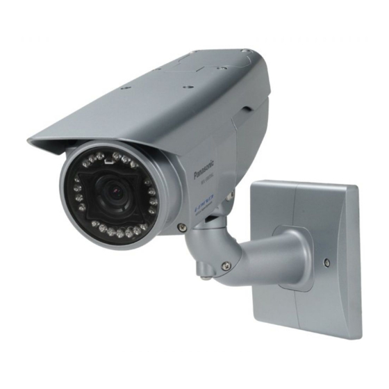
WV-SW316L/WV-SW316
Model No.
WV-SW314
WV-SW316LE/WV-SW316E
(This illustration represents WV-SW316.)
Before attempting to connect or operate this product, please read these
instructions carefully and save this manual for future use.
The model number is abbreviated in some descriptions in this manual.
Advertisement
Table of Contents

Related Manuals for Panasonic WV-SW316L


Summary of Contents for Panasonic WV-SW316L
-
Page 1: Installation Guide
Installation Guide Network Camera WV-SW316L/WV-SW316 Model No. WV-SW314 WV-SW316LE/WV-SW316E (This illustration represents WV-SW316.) Before attempting to connect or operate this product, please read these instructions carefully and save this manual for future use. The model number is abbreviated in some descriptions in this manual. - Page 2 á la norme spécifiée ou à tout autre For U.S. and Canada: document normatif conformément aux dispositions de WV-SW316L, WV-SW316, WV-SW314 la directive 2004/108/CE. For Europe and other countries: Nosotros declaramos...
-
Page 3: Table Of Contents
Major operating controls ......................16 Preparations ..........................19 Installations / Connections ......................20 Insert/remove an SDHC/SD memory card (WV-SW316L/WV-SW316 Only) ....... 28 Adjustment ..........................29 Mounting the front cover ......................33 Attaching the mounting surface on the top surface of the camera body........34 Using the CD-ROM ........................ -
Page 4: Important Safety Instructions
Important safety instructions 1) Read these instructions. 2) Keep these instructions. 3) Heed all warnings. 4) Follow all instructions. 5) Do not block any ventilation openings. Install in accordance with the manufacturer's instruc- tions. 6) Do not install near any heat sources such as radiators, heat registers, stoves, or other appara- tus (including amplifiers) that produce heat. -
Page 5: Limitation Of Liability
IMPROVEMENTS OF THIS PUBLICATION AND/OR THE CORRESPONDING PRODUCT (S). Disclaimer of warranty IN NO EVENT SHALL Panasonic System Networks Co., Ltd. BE LIABLE TO ANY PARTY OR ANY PERSON, EXCEPT FOR REPLACEMENT OR REASONABLE MAINTENANCE OF THE PRODUCT, FOR THE CASES, INCLUDING BUT NOT LIMITED TO BELOW:... -
Page 6: About Notations
The following notations are used when describing the functions limited for specified models. The functions without the notations are supported by all models. : The functions with this notation are available when using the model WV-SW316L. SW316L : The functions with this notation are available when using the model WV-SW316. -
Page 7: About The User Manuals
About the user manuals There are 2 sets of operating instructions for the WV-SW316L, WV-SW316, WV-SW314 (P model), WV-SW316LE, WV-SW316E (E model) as follows. • Installation Guide: Explains how to install and connect devices. • Operating Instructions (included in the CD-ROM): Explains how to perform the settings and how to operate this camera. -
Page 8: Trademarks And Registered Trademarks
* A phenomenon in which portions of the screen are displayed out of alignment • For information on the operation verification of the supported operating systems and web browsers, refer to our website at http://panasonic.net/pss/security/support/index.html. Trademarks and registered trademarks • Adobe, the Adobe logo, and Reader are either registered trademarks or trademarks of Adobe Systems Incorporated in the United States and/or other countries. -
Page 9: Network Security
Network security As you will use this unit connected to a network, your attention is called to the following security risks. q Leakage or theft of information through this unit w Use of this unit for illegal operations by persons with malicious intent e Interference with or stoppage of this unit by persons with malicious intent It is your responsibility to take precautions such as those described below to protect yourself against the above network security risks. -
Page 10: Precautions
Precautions Refer installation work to the dealer. Avoid installing this bracket in the loca- Installation work requires technique and experi- tions where salt damage occurs or corro- sive gas is produced. ences. Failure to observe this may cause fire, electric shock, injury, or damage to this product. Otherwise, the mounting portions will deterio- Be sure to consult the dealer. - Page 11 Do not touch this product, the power cord To keep on using with stable performance or the connected cables during thunder. Do not use this product in hot and humid con- (even in the process of work) ditions for a long time. Failure to observe this Failure to observe this may cause electric shock.
- Page 12 Transmission interval Discoloration on the color filter of the Image transmission interval may become slow MOS image sensor depending on the network environment, PC • When continuously shooting a bright light performance, shooting subject, access num- source such as a spotlight, the color filter ber, etc.
- Page 13 AVC Patent Portfolio License THIS PRODUCT IS LICENSED UNDER THE AVC PATENT PORTFOLIO LICENSE FOR THE PERSONAL USE OF A CONSUMER OR OTHER USES IN WHICH IT DOES NOT RECEIVE REMUNERATION TO (i) ENCODE VIDEO IN COMPLIANCE WITH THE AVC STANDARD ("AVC VIDEO") AND/OR (ii) DECODE AVC VIDEO THAT WAS ENCODED BY A CONSUMER ENGAGED IN A...
-
Page 14: Precautions For Installation
Precautions for installation Panasonic assumes no responsibility for injuries or property damage resulting from fail- ures arising out of improper installation or operation inconsistent with this documenta- tion. Installing place Design and engineer the power supply Contact your dealer for assistance if you are system to turn on/off the power of this product. - Page 15 Radio disturbance Time & date setting When this product is used near TV/radio anten- It is necessary to set the time & date before putting this product into operation. Refer to the na, strong electric field or magnetic field (near a motor, a transformer or a power line), images Operating Instructions on the provided may be distorted and noise sound may be pro-...
-
Page 16: Major Operating Controls
Major operating controls Rear part of sunshield Sunshield Front cover Rear cover Focus ring Zoom lock knob Safety wire Tilting table Zoom ring Tilting lock screw (x2) Azimuth Tilting lock screw adjustment ring Panning lock screw (This illustration represents WV-SW316.) Network cable RJ-45 (female) Alarm input/output cable... - Page 17 Link indicator (lit when linking) SDHC/SD memory card slot TELE button Auto focus (AF) button WIDE button Initial set button < WV-SW316L/WV-SW316 > Access indicator (lit when accessing) Link indicator (lit when linking) Focus assist (F.A.) button/ Extra optical zoom button Initial set button...
- Page 18 WV-SW316L WV-SW316 IR LED Lens Lens cover Packing Monitor output jack <WV-SW314> Lens Focus lock knob Zoom lock knob Packing Desiccant attachment position Lens cover Monitor output jack...
-
Page 19: Preparations
Preparations Caution: • FOR UL LISTED MODEL(S), ONLY CONNECT 12 V DC CLASS 2 POWER SUPPLY. • The camera mount bracket can be directly mounted on the wall using a junction box (locally procured) embedded in the wall, or a wall with a cable access hole. • The screws that secure the camera mount bracket on a wall are not supplied. Prepare the screws according to the material, structure, strength and other factors of the mounting area and the total weight of objects to be mounted. IMPORTANT: • Prepare the mounting screws according to the material of the area where the camera mount bracket and the adapter box are to be installed. -
Page 20: Installations / Connections
Installations / Connections Secure the camera to the camera mount bracket The tilt angle is locked downward at shipment. Loosen the tilting lock screw approx. 1 rotation and adjust the tilt angle of the camera to the horizontal position. Tighten the tilting lock screw again after tilt angle adjustment. Note: • Use a hexagonal wrench with width across flats of 4 mm (locally procured) to loosen or tighten the tilting lock screw. -
Page 21: Alarm Cable
Remove the screws from the mounting boss of the safety wire and the mounting boss of the cable clamp. Secure the safety wire with the screw from the mounting boss. Then, bundle the wire and the cable using the cable clamp and secure them with each screw from the mounting boss as illustrated. IMPORTANT: • Ensure that the safety wire is firmly secured. - Page 22 Connect the alarm input/output cable. SW316L SW316 <Ratings> Terminal name Ratings ALARM OUT, AUX OUT Open collector output (maximum applied voltage: 20 V DC) Open 4 V DC - 5 V DC by internal pull-up Close Output voltage 1 V DC or less (50 mA or less) ALARM IN, DAY/NIGHT IN Non-voltage make contact input (4 V DC - 5 V DC, internally pulled Open or 4 V DC - 5 V DC Make contact with GND (required drive current: 1 mA or more)
-
Page 23: Waterproof Tape
Waterproof treatment for the cable joint sections Adequate waterproof treatment is required for the cables when installing the camera with cables exposed or installing it under the eaves. The camera body is waterproof, but the cable ends are not waterproof. Be sure to use the supplied waterproof tape at the points where the cables are connected to apply waterproof treatment in the following procedure. - Page 24 Connection example when connecting to a network using a PoE hub Monitor for adjustment (for adjustment use only) Powered speaker (option) PoE device (hub) LAN cable (category 5 or better, straight, STP*) Microphone (option) LAN cable (category 5 or better, straight, STP*) Powered speaker (option)
- Page 25 Secure the camera mount bracket when the camera is directly installed on a wall 6 mm (W) x 10 mm (L) {1/4" (W) x 3/8" (L)} (long hole) Use 4 screws (locally 46 mm {1-13/16"} procured) to secure the 20 mm camera mount bracket to a {13/16"} wall or a junction box (locally...
-
Page 26: Adapter Box (E Model Only)
• If a junction box is used, putting the View from above (internal) boxes side by side is recommended as shown in the 46 mm 83.5 mm illustration at right. {1-13/16"} Unused junction {3-1/4"} (Use unused boxes junction boxes to 6 mm (W) x 10 mm (L) pass cables {1/4"... - Page 27 Secure the mount bracket cover x2 (accessories) to the Mount bracket cover x2 (accessories) camera mount bracket with the 2 mount bracket cover screws (accessories). IMPORTANT: • Ensure that the mount bracket cover screws (accessory) are firmly secured. Camera mount bracket Recommended tightening torque: 0.59 N·m {0.44 lbf·ft} Mount bracket cover screw x2 (M3 x 6) (accessories)
-
Page 28: Insert/Remove An Sdhc/Sd Memory Card (Wv-Sw316L/Wv-Sw316 Only)
Insert/remove an SDHC/SD memory card (WV-SW316L/WV-SW316 Only) IMPORTANT: • Before inserting an SDHC/SD memory card, turn off the power of the camera first. • When inserting an SDHC/SD memory card, make sure the direction. • Before removing the SDHC/SD memory card, select "Not use" for "SD memory card" on the [SD memory card] tab of the setup menu first. Turn off the power after "Not use" selection, and then unload the SDHC/SD memory card. When the SDHC/SD memory card is inserted or removed with the power on, data in the SDHC/SD memory card may be damaged. -
Page 29: Adjustment
Adjustment Be sure to view the monitor for adjustment when the camera angle is adjusted. Supply power to this unit, connect the monitor for adjustment (e.g. a small LCD) to the monitor output jack, and adjust the camera angle (turn off the power after view angle adjustment for safety). q Loosen the 4 fixing screws of the front cover to remove the front cover. - Page 30 Adjust the angular field of view and the focus. Adjust the angular field of view in accordance with the distance between the camera lens and a photographic subject. These adjustments shall be performed together with the camera angle adjustment. <WV-SW316L/WV-SW316> Auto focus (AF) button TELE button WIDE button...
- Page 31 Note: • When shooting in the following place or the following subjects, focus may not be adjusted automatically. In this case, adjust the focus manually from the setup menu. Refer to the Operating Instructions (included in the CD-ROM) for how to perform the manual focus adjust- ment from the setup menu.
- Page 32 w To adjust the angular field of view with a higher zooming effect even after adjusting the angular field of view almost fully in the "T" direction, hold down the focus assist button (F.A.)/extra opti- cal zoom button for 5 seconds or more. 2x extra optical zoom will be applied. When the image capture size under "VGA"...
-
Page 33: Mounting The Front Cover
Mounting the front cover <WV-SW316L/WV-SW316> Mount the front cover. Fixing screw x4 <WV-SW314> Attach the desiccant (accessory) to the inner bottom side of the front cover along the guide rib, and mount the front cover. Guide rib Desiccant (accessory) Fixing screw x4 IMPORTANT: • Be sure to attach the desiccant (accessory). Refer to the instructions for the desiccant for how... -
Page 34: Attaching The Mounting Surface On The Top Surface Of The Camera Body
Attaching the mounting surface on the top surface of the camera body When the mounting surface is changed to the top surface of the camera body Remove the 4 sunshield fixing screws from the camera body and remove the sunshield. Remove the 4 tripod head fixing screws from the camera body and remove the tripod head. - Page 35 Mount the tripod head on the top of the camera body with the 4 tripod head mounting screws that were removed in the step 2. IMPORTANT: • Caution shall be taken to prevent each cable from being caught between the camera body and tripod head. • Be sure to use the screws that were removed from the tripod head. Recommended tightening torque: 0.59 N·m {0.44 lbf·ft} Secure the camera to the camera mount bracket with the camera fixing screws x3 (accessory). Pass each cable and the safety wire through the camera mount bracket, and connect the safe- ty wire to the camera mount bracket.
- Page 36 Remove the sunshield backside. As illustrated, opening up the sunshield in both directions makes it easier to remove the rear part of the sunshield. • When installing the camera to a ceiling, the rear part of the sunshield and the fixing screws are not used.
-
Page 37: Using The Cd-Rom
License Agreement will be displayed. • Read the Agreement and choose "I accept the term in the license agreement", and click [OK]. Then the launcher window will be displayed. • If the launcher window is not displayed, double click the "CDLauncher.exe" file on the CD-ROM. Using the supplied CD-ROM, the following actions can be performed. q The Panasonic IP setting software can be installed on the PC. → Refer to "Installing Panasonic IP setting software". ( Page 38) ☞ w Settings related to the camera's network can be set from the Panasonic IP setting software. -
Page 38: Installing Panasonic Ip Setting Software
On the CD launcher window, click the [Install] button next to [IP Setting Software] to display the Panasonic IP setting software installation window. Confirm the following settings before starting the installation. q Select the Panasonic IP setting software to install. w Select where to create the Panasonic IP setting shortcut icon when the Panasonic IP setting software is installed. e Specify which folder on the PC to install the Panasonic IP setting software to. r Click the [Install] button to start the installation. Note: • To uninstall the Panasonic IP setting software delete the shortcut icon from where you specified it to be installed (the default is on the desktop) during installation and the [EasyIPConfig] folder from the folder you specified during Panasonic IP setting software installation. -
Page 39: Installing The Manuals
Installing the manuals On the CD launcher window, click the [Install] button next to [Manual] to display the Manual installa- tion window. Confirm the following settings before starting the installation. q Select which manuals to install. The camera models that the manuals support are displayed in w "Model List". w The camera models that are supported by the manuals selected in q are displayed here. e Select where to create the manuals shortcut icon when the manuals are installed. r Specify which folder on the PC to install the manuals to. t Click the [Install] button to start the installation. Note: • To uninstall the manuals delete the shortcut icon from where you specified it to be installed (the default is on the desktop) during installation and the [Manual] folder from the folder you specified during the manuals installation. Installing the Viewer software The Viewer software (Network Camera View4S) must be installed on the PC in order to display camera images. On the CD launcher window, click the [Install] button next to [Viewer Software], and follow the instructions displayed on the window to install the software. A message is displayed if a... -
Page 40: Configure The Network Settings
Configure the network settings Configure the network settings of the camera using the Panasonic IP setting software It is possible to perform the network settings of the camera using the IP setup software on the pro- vided CD-ROM. When using multiple cameras, it is necessary to configure the network settings of each camera independently. If the Panasonic IP setting software does not work, configure the network settings of the camera and the PC individually on the "Network" page of the setup menu. Refer to the Operating Instructions (included in the CD-ROM) for further information. IMPORTANT: • When using Microsoft Windows 7 or Microsoft Windows Vista, the "Windows Security Alert"... - Page 41 Complete each network setup item and click the [Save] button. Note: • By unchecking the "Wait for camera restarting." checkbox, multiple cameras can be continuously configured. IMPORTANT: • It may take for around 2 minutes to complete to upload the settings to the camera after clicking the [Save] button. The settings may be invalidated when the LAN cable is disconnected before completing the upload. In this case, perform the settings again. • When using a firewall (including software), allow access to all UDP ports. About the default user name and password Click the [Setup] button on the "Live" page, the user authentication window will be displayed. Enter the default user name and password as follows, and log in.
-
Page 42: Troubleshooting
Troubleshooting Before asking for repairs, check the symptoms with the following table. Contact your dealer if a problem cannot be solved even after checking and trying the solution in the table or a problem is not described below. Reference Symptom Cause/solution pages SW316L... -
Page 43: Specifications
Specifications • Basic Power source: SW316L SW316 12 V DC, PoE (IEEE802.3af compliant) SW314 PoE (IEEE802.3af compliant) Power consumption: SW316L SW316 12 V DC*: 850 mA, PoE 48 V: 200 mA (Class 0 device) SW314 PoE 48 V: 70 mA (Class 0 device) * FOR UL LISTED MODEL(S), ONLY CONNECT 12 V DC CLASS 2 POWER SUPPLY. - Page 44 • Camera Image sensor: 1/3-type MOS image sensor Effective pixels: Approx. 1.3 megapixels Scanning area: 4.80 mm (H) × 3.60 mm(V) {3/16 inches (H) x 5/32 inches (V)} Scanning system: Progressive Minimum illumination: SW316L Color: 0.3 lx {0.03 footcandle} (F1.3, Auto slow shutter: Off (1/30 s), Gain: On(High)) 0.019 lx {0.0019 footcandle} (F1.3, Auto slow shutter: max.
-
Page 45: • Camera Mount Bracket
Video analytics On/Off (with the XML notification setting) Face detection: Privacy zone: On/Off (up to 2 zones available) VIQS: On/Off Camera title on screen: Up to 20 characters (alphanumeric characters, marks) On/Off Video motion detection (VMD alarm): On/Off, 4 areas available • Lens Zoom ratio: SW316L... - Page 46 • Network Network: 10BASE-T/100BASE-TX, RJ45 connector Resolution: Aspect ratio: 4:3 H.264 1280×960/ VGA (640×480)/ QVGA (320×240), max. 30 fps MPEG-4 VGA (640×480)/ QVGA (320×240), max. 30 fps JPEG (MJPEG) 1280×960/ VGA (640×480)/ QVGA (320×240), max. 30 fps Aspect ratio: 16:9 H.264 1280×720/ 640×360/ 320×180, max.
- Page 47 Up to 16 camera images can be displayed simultaneously on a multi-screen. (Including the camera itself ) Compatible SDHC/ Manufactured by Panasonic SD memory card (option): SDHC memory card: 4 GB, 8 GB, 16 GB, 32 GB SD memory card: 256 MB, 512 MB, 1 GB, 2 GB...
-
Page 48: Standard Accessories
Standard accessories Installation Guide (this document) ............1 pc. Warranty card (P model only) .............1 pc. CD-ROM* ..................1 pc. Code label* ..................1 pc. The following parts are used during installation procedures. 4P alarm cable ..........1 pc. SW316L SW316 2P power cable ..........1 pc. - Page 50 Panasonic Marketing Europe GmbH Three Panasonic Way, Secaucus, Winsbergring 15, 22525 Hamburg F.R.Germany New Jersey 07094 U.S.A. Panasonic Canada Inc. 5770 Ambler Drive, Mississauga, Ontario, L4W 2T3 Canada (905)624-5010 www.panasonic.ca © Panasonic System Networks Co., Ltd. 2012 Cs1111-2012 PGQX1054XA Printed in China...