Table of Contents
Advertisement
Quick Links
Advertisement
Table of Contents

Related Manuals for Alto Poseidon 7


Summary of Contents for Alto Poseidon 7
- Page 1 Poseidon Index Service Manual TsJ 6-03.02...
- Page 2 Technical Data Construction Function Trouble-shooting Index Service/Repair Poseidon Adjustment/Test Wiring Diagrams Spare Parts Proposal Special Information...
-
Page 3: Technical Data
Technical Data Poseidon 1200 Primary data Unit General Nominal values Tolerances Voltage +6/-10% Frequency Motor coupling Number of phases Pce. Power consumption +-1.5 High voltage 2.4 in 2 sec. Leakage current 0.75 Resistance in ground circuit Absorption power Axel power Revolutions Min-1 1440... - Page 4 Technical Data Poseidon 1280 Primary data Unit General Nominal values Tolerances Voltage +6/-10% Frequency Motor coupling Number of phases Pce. Power consumption +-1.5 High voltage 2.4 in 2 sec. Leakage current 0.75 Resistance in ground circuit Absorption power Axel power Revolutions Min-1 1440...
- Page 5 Technical Data Poseidon 720 Primary data Unit General Nominal values Tolerances Voltage +6/-10% Frequency Motor coupling Number of phases Pce. Power consumption +-1.5 High voltage 2.4 in 2 sec. Leakage current 0.75 Resistance in ground circuit Absorption power Axel power Revolutions Min-1 1430...
-
Page 6: Start/Stop System
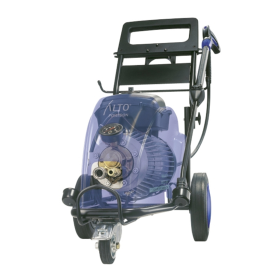
Construction Frame The frame is built of Ø25mm steel pipes. One nozzle can be stored on each side of the machine. 2, Ø250mm wheels and 1, Ø100mm swivel wheel are mounted to the frame. A bent bar is attached to the front of the frame to protect hose attachments. The bar is also used for lifting the machine both manually and by crane. -
Page 7: Electrical System
Construction Electrical system The electrical system is located in electrical casing placed on the motor/pump unit. All automatic functions are controlled by a microprocessor built into a circuit board. Equipment The machine’s standard equipment consists of: Ergo 3000 spray handle. 10 mtr. -
Page 8: Pump Function
Function Pump Function The illustration below shows a cross-section of the Poseidon pump. The pump’s job is to move a given amount of water from the suction side to the high-pressure nozzle. The volume of water depends on the pistons’ quantity, diameter, impact length, and number of impacts per minute. - Page 9 Function Bypass Valve Function The bypass valve has 4 functions: 1. Protect the machine against excess pressure. 2. Relieve the pressure in bypass. 3. Fast conversion to high-pressure. 4. Ensure 0 pressure when the machine is stopped. Operation: The water from the pump is led into chamber A of the bypass valve. From there, the water passes through hole B in piston C and out of the machine.
- Page 10 Function P O S E I D O N S P R A Y Poseidon_GB01...
- Page 11 Function P O S E I D O N B Y - P A S S Poseidon_GB01...
-
Page 12: Flow Control
Function Flow Control Flow control consists of: 1. Casing 2. Piston w/ magnet 3. Spring 4. Reed switch Operation: A drop in pressure in the piston pushes the piston forward, causing the magnet to activate the reed switch. A drop in pressure on the piston’s end face causes the piston to remain in this position. Bypass: When water is not being consumed, the drop in pressure in the piston stops, and the piston is pushed back by the spring, deactivating the reed switch. - Page 13 2. Read-out of number of starts. 3. Read-out in hours/minutes of operating time under flow. 4. Read-out in hours/minutes of bypass time. These read-outs are made with ALTO SB Datalogger . A description of SB Datalogger will be added later. Poseidon_GB01...
-
Page 14: Troubleshooting
Trouble-shooting Operating Requirements To ensure error-free operation, the following requirements must be met: Machine and equipment must be free of air and without leaks. Water temperature must not exceed 85°C when inlet pressure on water supply. In suction mode, water temperature must be significantly lower, depending on the suction height. -
Page 15: Safety Valve
Service/Repair Safety valve The safety valve’s factory setting for opening pressure = working pressure + 25 to +30 bars. Upon each service inspection the setting must be tested and, if necessary, adjusted. When mounting, affix ball and pressure plate to the spring with lubrication. The seat is screwed on using a 10mm socket wrench (no gasket required). - Page 16 Service/Repair Valve cylinder head 1 Removal and mounting is done manually. Lubricate the large O ring with grease. Lubrication duct Pressure valve seat Suction valve seat Nylon ring Textile sleeve (hard) Back-up ring Rubber sleeve (soft) Remove the suction valve seat using impact piercer no. 1216506. Press out the pressure valve using a 2 mm piercer.
- Page 17 Service/Repair Valve cylinder head 2 Lock/back-up ring O-ring Rubber sleeve secondary Thrust collar Back-up ring Textile sleeve Expansion/back-up ring Suction valve Pressure valve O-ring When mounting textile sleeves, use tool no.: 1220090. It helps to place the sleeves in a water bath 3-4 hours before mounting. Remember to blow through the lubrication ducts with compressed air.
-
Page 18: Cylinder Block
Service/Repair Cylinder block 1 Oil filling Plate O-ring Torque: 37 Nm Oil sleeve Back-up ring Oil draining Always replace secondary sleeves when replacing pressure sleeves. Check for free passage in the thrust collar’s drainage holes. Drain the oil by loosening the plug at the bottom of the cylinder block. - Page 19 Service/Repair Cylinder block 2 Carefully lift the oil sleeves out with a suitable screwdriver and dispose of them. Be careful not to scrape the surface. Before inserting the new sleeves, it is a good idea to moisten the sleeves with soapy water. Insert new oil sleeves using piercer no.
- Page 20 Service/Repair Motor / wobble disc 1 The motor consists of a stator with windings, a rotor with an axel that is held in place with a bearing in the N-bearing cover and the wobble disc’s innermost needle bearing in the D-bearing cover. Ventilator 4 is pressed onto the rotor over locking bush 5 and is mounted with two screws.
- Page 21 Service/Repair Motor / wobble disc 2 When mounting complete D bearing cover, protect the oil sleeve using tool no. 1206598, and place it on the axel before mounting When mounting the wobble disc, lubricate the bearings with oil. The large roller bearings 25 and 31 are identical.
- Page 22 Adjustment/Test Adjustment of reed switch Place the reed switch in the plastic case with the screw loose enough so that the switch can still be moved back and forth. Place the reed switch as far forward in the direction of the water outlet as possible. Start the machine on setting 1, without a water connection.
- Page 23 Adjustment/Test Torque Poseidon_GB01...
- Page 27 Spare Parts Proposal 1 8 0 2 5 2 9 6 1 0 0 6 6 6 6 3 0 1 1 6 6 2 6 0 2 2 7 4 9 7 = 1 1 1 9 5 7 1 9 8 = 1 1 1 9 8 2 0 9 9 = 1 1 1 9 5 7 0 6 1 0 0 6 1 0...
- Page 28 Spare Parts Proposal 1 0 1 1 1 9 4 1 0 3 0 0 1 1 7 9 3 6 0 1 2 6 2 6 4 4 1 6 1 0 1 0 4 2 3 0 0 1 7 1 6 6 1 0 1 0 6 1 1 6 0 2 9 4 5 6 1 0 0 9 4 1...
- Page 29 Spare Parts Proposal 6 1 0 0 6 1 1 3 2 0 0 6 2 3 6 1 0 1 7 4 9 3 2 0 0 6 5 6 1 8 0 2 5 1 1 3 2 0 0 6 1 5 3 2 0 0 6 1 5 9 8 = 1 1 1 9 8 2 0 9 9 = 1 1 1 9 5 7 0...