Table of Contents
Advertisement
Advertisement
Table of Contents

Related Manuals for Meridian 565


Summary of Contents for Meridian 565
- Page 1 Meridian 565 Digital Surround Processor...
- Page 2 Nimbus Records Ltd. Trifield is a trademark of Trifield Productions Ltd. LaserDisc is a trademark of Pioneer Electric Corp. Boothroyd|Stuart Meridian, Meridian, Meridian Digital Theatre, MLP, and LipSync are registered trademarks of Meridian Audio Ltd. This guide was produced by Human-Computer Interface Ltd, Cambridge, England.
-
Page 3: Table Of Contents
Contents Introduction Introduces the digital surround processor, and gives guidelines and suggested layouts to help you plan your surround system. Planning a system ... 2 Planning sources ... 6 Setting up the digital surround processor Describes how to unpack and install the digital surround processor, and gives details of the video and speaker connections. - Page 4 Calibrating the system 33 Explains how to use the digital surround processor’s built-in calibration procedure and test signals to set up your system for the best possible sound. Using the calibration procedure ... 34 Calibration tests ... 36 Test signals ... 44 Setting up sources Explains how to set up the sources connected to your digital surround...
-
Page 5: Introduction
Once you have set up the 565, or if it has been set up for you by your dealer, refer to the Meridian 565 Digital Surround Processor User Guide for information about using the 565, and getting superb results from all your music and cinema recordings. -
Page 6: Planning A System
565. The digital surround processor can be configured to work with a wide range of different speaker layouts. These include... - Page 7 Four-channel surround system (Layout M, 2 Surrounds) If you are primarily interested in home cinema you may prefer to extend an existing stereo system by adding a pair of rear surround speakers, for cinema effects and ambient sounds. For cinema the surround speakers do not take a huge strain, so small units can be used such as in-wall or bookshelf-mounted speakers.
- Page 8 THX system (Layout A) If your primary interest is cinema, you can use a mono subwoofer to enhance the bass performance for both cinema and music presets. This is the configuration recommended by Dolby and THX for use with Pro Logic, and is a good choice if you want to enhance the bass from the main left and right speakers, or your room is large.
- Page 9 Meridian DSP6000 Digital Loudspeakers, a DSP6000C Digital Centre Loudspeaker, and four DSP5000 or DSP5500 Digital Loudspeakers. Using the 565 with Meridian DSP Loudspeakers Meridian systems will often contain two or more units that can be controlled by the Meridian System Remote infra-red remote control.
-
Page 10: Planning Sources
LaserDisc player to both a digital and an analogue input. If you have a 7.1 version of the 565 you can take advantage of Dolby Digital LaserDiscs by connecting the LaserDisc player to the 565 via a 519 Demodulator; see To connect to a 519... -
Page 11: Connections
Setting up the digital surround processor his chapter explains how to install the digital surround processor. It describes what you should find when you unpack the processor, how you should connect it to your other audio equipment and speakers, and the siting constraints. -
Page 12: Unpacking
500 Series communications lead. Digital-audio cable. This manual. The Meridian 565 Digital Surround Processor User Guide. If any of these items are missing please contact your dealer. We suggest that you retain the packing in case you need to transport the unit. -
Page 13: Connecting The Digital Surround Processor
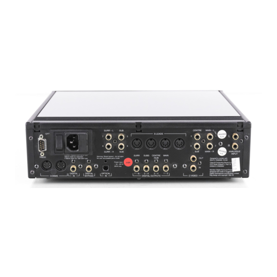
Connecting the digital surround processor Rear panel RS232 connection RS232 DIGITAL DIGITAL COMMS BYPASS Digital Comms input Video connections The table opposite gives details of the two video connections. To take advantage of the on-screen display both these connections must be made. Analogue S-Lead outputs 5 –... -
Page 14: Audio Inputs
Audio inputs The following table gives details of the three audio inputs: Use this input To connect to this ANALOGUE INPUT An analogue source such as a TV, L and R video recorder, radio tuner, or analogue preamplifier. DIGITAL IN A digital source, such as the 562 or 562V Digital Control Unit, or a CD player. -
Page 15: Communications Connections
To distribute the S-lead connections from the master digital speaker to other slave digital speakers. RS232 connection The RS232 connection is for future expansion, to allow the 565 to be interfaced to a computer. Contact your dealer for more information. -
Page 16: Connecting Video
VIDEO OUT C-VIDEO Video lead If your surround system includes a television the 565 can add a text overlay to the video signal, to provide additional information about its operation in the form of a textual on-screen display (OSD). In normal operation this repeats the information provided on the 565 front panel display. -
Page 17: Connecting Speakers
Link all the other digital speakers together using S5 leads, as shown in the illustration. The other S-LEAD sockets on the back of the 565 can be used to distribute the comms to each slave speaker. Use the duplicate sockets on each digital speaker to link the... - Page 18 To connect to a 556 or 557 Stereo Power Amplifier or other power amplifier 565 Digital Surround Processor MAIN-L MAIN-R Connect the appropriate outputs from the digital surround processor to the power amplifier line inputs, using screened audio cable. Connect the speaker outputs from the power amplifier to suitable speakers.
-
Page 19: Connecting Sources
519 optical input. Connect the 519 output to the 565 OPTICAL IN using an optical cable. If you are using the 565 with a 562/562V Digital Control Unit connect the 519 to the 562/562V optical input, instead of to the 565. - Page 20 565 Digital Surround Processor DIGITAL Digital lead Connect the main digital output of the 562 or 562V to the 565 DIGITAL IN, using high-quality 75 screened cable. Connect all the analogue and digital sources you want to use to the appropriate inputs of the 562 or 562V.
- Page 21 Connect the 551 tape output to the 565 ANALOGUE INPUT, using a pair of phono leads. Connect the two analogue outputs from the 565 that you want to use to the tape input (A4) of the 551. Connect one digital input, such as CD, and one optical input, such as LaserDisc, directly to the 565.
-
Page 22: Connecting To Other Meridian Equipment
COMMS sockets on another 500 Series unit, using the 500 comms lead provided with the 565 Digital Surround Processor. The sequence in which you connect the units is not important. 586 DVD Player... -
Page 23: Arrangement You Want To Use
Type settings, which are designed to set most of the parameters to typical values. The next stage is to configure the 565 for those aspects of your layout that differ from the standard setting you chose. -
Page 24: Choosing Standard Settings
Switch off any power amplifiers that are connected to the 565 and put any digital speakers to standby. Switch off the 565, using the power switch on the back panel. Switch on the power again while holding down the Off key on the front panel. - Page 25 (Layout A) Types 0 to 5 configure all the sources, except for CD, CDR, and LD, to use the 565 analogue input. These are ideal for using the 565 on its own or with an analogue preamplifier, such as the 501/501V Control Unit.
-
Page 26: Specifying The Speaker Layout
Each entry shows the size or position of the corresponding speaker(s), followed in brackets by the number of the 565 output they should be connected to. Large main speakers... - Page 27 If you have a subwoofer you can use it to augment the bass from the centre channel (Layouts B or H). If the subwoofer is not very high quality we recommend using it only for the cinema presets, and not for music (Layouts AB or AG). With Dolby Digital sources an additional option is to use the subwoofer for the LFE channel.
-
Page 28: Speaker Layouts
Speaker layouts Main Centre None Large (1, 2) Small (3) Large (3) None Small (1, 2) Small (3) Subwoofers Sides None Optional (5, 6) None Optional (5, 6) Centre (4) Optional (5, 6) Centre (4) cinema presets only Optional (5, 6) Mono (4) cinema presets only Optional (5, 6) Centre (4), Surround (5) - Page 29 To set the speaker layout Switch off the 565, using the power switch on the back panel. Switch off any power amplifiers that are connected to the 565. Switch on the power again while holding down the Display key on the front panel.
- Page 30 To specify the number of surround speakers Press > or < until you see a display such as: Press A or V to step between the following options: Option What it means No Surrounds No rear speakers. One centre rear speaker (should be 1 Surround connected to REAR-R).
- Page 31 To select a 5.1 LFE subwoofer If you have the 7.1 version of the 565 you can add an LFE subwoofer to layouts that do not normally have one (such as G, L, or M), or choose an LFE subwoofer instead of a mono subwoofer in layouts that have a subwoofer (such as A).
-
Page 32: Setting Up The Speaker Outputs
Setting up the speaker outputs The next stage in configuring the 565 is to specify information about each of the speakers in your layout, and adjust their delays to time-align the system so that sounds are coincident when they arrive at the listening position. - Page 33 To set up a speaker output Switch off the 565, using the power switch on the back panel. Switch off any power amplifiers that are connected to the 565. Switch on the power again while holding down the Source key on the front panel.
- Page 34 Use A and V to choose between the following options: Choose this For this type of speaker Meridian A Meridian DSP Loudspeaker such as the DSP5000, DSP5000C, DSP6000, or DSP6000C connected to the appropriate digital output. Digital A digital signal for feeding a DAC directly from the appropriate digital output.
- Page 35 To set up speaker protection for 5.1 sources Because of the high bass levels that 5.1 channel sources are capable of reproducing, the digital surround processor allows you to set up automatic protection of each full-range speaker or subwoofer in your system. Press >...
- Page 36 To specify the type of subwoofer Press > or < until you see a display such as: Press A or V to specify the subwoofer filtering. The options are shown in the following table: Option Description Narrow The digital surround processor provides an 80Hz cutoff;...
-
Page 37: Calibrating The System
Calibrating the system o help you to set up your installation to give the best possible sound with any particular combination of associated equipment the digital surround processor includes a built-in calibration procedure. This calibration procedure uses test signals to present a series of sounds, which you use to adjust certain aspects of the system to their optimum settings. -
Page 38: Using The Calibration Procedure
Each calibration test uses a test signal designed to give the best results. For information about choosing an alternative test signal, or one of the 565 inputs, see To select a different test signal, page 44. Using a Sound Pressure Level meter... - Page 39 To start the calibration procedure Put the 565 into standby by pressing the Off key. Press and hold the front panel Off key for at least five seconds. The display shows: After a few seconds the display shows: followed by: Levels is the name of the first calibration test.
-
Page 40: Calibration Tests
Calibration tests Levels This test allows you to adjust the output level to each speaker individually, and it follows the general guidelines from Dolby and Lucasfilm. A Sound Pressure Level (SPL) meter can be useful at this stage; ask your dealer for more information. After a short delay the display shows: Use the ] and [ keys on the Meridian System Remote to move between each of the speakers in the layout in the... - Page 41 Main This test allows you to set the relative phase and the relative delay between the left and right main speakers. The Low test signal is now presented equally and in phase on just the left and right main speakers; see Test signals, page 44, for details of the signals.
- Page 42 Centre Phase As in the previous test, signals are applied to the main left, right, and centre speakers to allow you to adjust the relative phase and delay on the centre channel. Use > and < to switch between phase and delay. When setting phase the display shows the absolute phase of the centre speaker.
- Page 43 As you increase the delay the centre speaker will appear to move away from you. In practice we usually find that the ideal delay setting is +0.5 more than the value used to time-align the system. For example, if the original value was +1.0' adjust it to: This is equivalent to moving the centre speaker away from the listener.
- Page 44 Surround This test presents the Low test signal through the left and right rear surround speakers to allow you to adjust the relative phase and delay between them. Use > and < to switch between phase and delay. When setting phase the display shows the absolute phase of the left surround speaker.
- Page 45 Sides If your layout includes side surround speakers an additional Sides option allows you to adjust the relative phase and delay. Side L presents the signal to the front left, rear left, and side left speakers and you adjust the phase of the side left speaker for reinforcement, as with Centre Phase.
- Page 46 Choose the position in which the subwoofer reinforces the sound from the main speakers in the crossover region. You should not adjust the delay as this has already been specified when you time-aligned the layout. Other subwoofers Press Store to adjust any additional subwoofers in the system in exactly the same way.
- Page 47 This test provides metering to help you set the level of the analogue inputs. The analogue-to-digital converter (ADC) fitted for the analogue input to the 565 has a sensitivity of 2V rms for full scale. With this setting, the analogue input can be connected to the output of a LaserDisc or CD player and will not require adjustment.
-
Page 48: Test Signals
Test signals In Calibration you can make adjustments using a number of different signals, shown in the table below. Normally the 565 selects the most appropriate signal for the test. Signal Description High Continuous ‘pink’ noise, band-limited 500Hz–2kHz. Continuous ‘pink’ noise, band-limited 20Hz–80Hz. -
Page 49: Setting Up Sources
Setting up sources his chapter explains how to set up the sources connected to the digital surround processor, and configure them to suit your other equipment. When you set up the digital surround processor to one of the standard settings, 12 sources are automatically set up for you. If you wish, you can configure each source individually to choose its label, the audio input it selects, and the DSP preset it uses. -
Page 50: Standard Source Settings
Standard source settings The digital surround processor provides 12 sources corresponding to the 12 source selection keys on the Meridian System Remote. Source Types 0 – 5 Digital Radio Analogue Analogue Analogue Tape 1 Analogue Tape 2 Analogue Digital Cable Analogue Digital VCR 1... - Page 51 Series equipment. The procedure for doing this is as follows. To configure a source Switch off the 565, using the power switch on the back panel. Switch on the power again while holding down the Display key on the front panel.
- Page 52 The options are summarised in the following table: Option Initial value Label C D C D Audio input CD Digit.In 2-channel preset CD Music Precision CD 16 Bits Comms type C D 1 C Address C D 1 A Digital preset C D D i g i t a l DTS preset C D D T S...
- Page 53 DTS delay D T S D e l a y Y The last valid, or L.V. options leave the corresponding setting unchanged from its previous value. For a full list of presets see the 565 User Guide. Alternative values Explanation...
-
Page 54: Examples Of Configuring The Sources
Examples of configuring the sources The following examples illustrate how you can configure the source options to your own requirements. To change a source label Display the source you want to configure, together with its current label, as described in To configure a source, page 47. For example, to configure the Radio source label choose: Press A or V to step between the alternative labels. - Page 55 To set up a system with two Meridian CD players Configure the source you are going to use for the first CD player. For example: Source CD, Label C1, Audio input Digit.In, Comms type 1C, Address 1A. Configure the source you are going to use for the second CD player, with a different address.
-
Page 57: Troubleshooting
If you are still not able to resolve a difficulty with the help of this guide and the suggestions in the following pages, please contact your Meridian dealer or Meridian Audio Ltd. -
Page 58: General Operating Problems
The power switch on the rear panel of the 565 is turned on. If the 565 will still not illuminate, check any fuses in your power supply and the fuse in the inlet of the 565. If these are all intact, contact your dealer. -
Page 59: Audio Problems
Audio problems Hum on analogue input There is no reason for the 565 to produce hum on the analogue input. Check the source equipment. Disconnect each source in turn. If the hum originates from a ground loop an antenna or cable supply may be the cause, in which case an antenna-lead isolator should be fitted. - Page 60 CD may also be quieter when it is stopped, producing so called ‘digital silence’. The 565 has a 16-bit capability on its internal analogue-to-digital converter, which is used for analogue sources. When the volume is turned up high you may hear its dither as a hiss when the sources are stopped.
- Page 61 There is a hiss when starting DTS LaserDiscs The DTS audio stream is indistinguishable from a PCM audio stream; the 565 takes 30 msec to identify the encoding, during which a hiss is heard. With non-video DTS sources you can add a 30 msec delay to avoid this.
-
Page 62: Video Problems
TV does not work using the 565 Check all video connections; the input is the lower connector of the pair. Temporarily remove the 565 from the video circuit. The fault will probably be elsewhere or in a cable. Poor picture quality... -
Page 63: Index
Index Ambisonic 4 Analogue input 10 setting sensitivity 43 Analogue preamplifier 6 Analogue speakers, connecting 10 Aspect ratio, specifying 25 Audio inputs 10 Audio outputs 10 Automatic setup 18 Calibration procedure 33 exiting 35 starting 35 Calibration tests 36 ADC Check 43 Centre Phase 38 Front-Rear 39 Levels 36... - Page 64 Digital connections, cables 11 DIGITAL IN 10 DSP Loudspeakers. See Meridian DSP Loudspeakers DSP preset, using source keys to change 50 501/501V Control Unit 6 connecting to 16 519 Demodulator 6 connecting to 15 551 Integrated Amplifier, connecting to 17 555 Stereo Power Amplifier, connecting to 14 562/562V Digital Control Unit 6...
- Page 65 On-screen display (OSD) during calibration 34 troubleshooting 58 Optical connections 11 OPTICAL IN 10 Planning a system 2 Planning sources 6 Poor picture quality 58 Poor sound quality 55 Positioning 8 Product address 27 Radio interference 8, 55 Rear panel 9 RS232 connection 11 Setting up sources 45 Setting up the Digital Surround...
- Page 66 Types 20 standard 46 with 562 21, 46 Unpacking 8 Video connections 9 Volume mode 27...