Table of Contents
Advertisement
Instructions - Parts
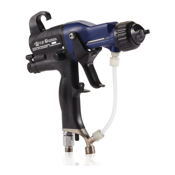
Pro Xp™ Electrostatic
Air Spray Gun
For use in Class I, Div. I Hazardous Locations using Group D spray materials.
For use in Group II, Zone 1 Explosive Atmosphere Locations using Group IIA spray materials. For
professional use only.
Important Safety Instructions
Read all warnings and instructions in this manual. Save these
instructions.
100 psi (0.7 MPa, 7.0 bar) Maximum
Fluid Working Pressure
100 psi (0.7 MPa, 7.0 bar) Maximum Air
Working Pressure
See page 3 for model part numbers and
approval information.
PROVEN QUALITY. LEADING TECHNOLOGY.
3A2494E
EN
Advertisement
Table of Contents
Troubleshooting

Related Manuals for Graco Pro Xp L40T10


Summary of Contents for Graco Pro Xp L40T10
- Page 1 Instructions - Parts Pro Xp™ Electrostatic 3A2494E Air Spray Gun For use in Class I, Div. I Hazardous Locations using Group D spray materials. For use in Group II, Zone 1 Explosive Atmosphere Locations using Group IIA spray materials. For professional use only.
-
Page 2: Table Of Contents
Air Cap and Nozzle Replacement....38 Hoses ............75 Electrode Replacement ........ 39 Fluid Packing Rod Removal......40 Dimensions ............76 Packing Rod Repair ........40 Technical Data ........... 77 Barrel Removal ..........42 Barrel Installation ......... 42 Graco Pro Xp Warranty ........78 3A2494E... -
Page 3: Models
Models Models Part No. Nozzle Standard Smart Standard High Increased Display Display Coatings Conductivity/ Transfer Round High Wear Efficiency Spray L40T10 ✔ ✔ ✔ L40T14 ✔ ✔ ✔ ✔ L40T15 ✔ ✔ ✔ ✔ L40T16 ✔ ✔ ✔ L60T10 ✔ ✔... -
Page 4: Warnings
• Ground all equipment, personnel, object being sprayed, and conductive objects in or close to spray area. Resistance must not exceed 1 megohm. See Grounding instructions. • Only use grounded Graco conductive air supply hoses. • Do not use pail liners unless they are conductive and grounded. - Page 5 Warnings WARNING PRESSURIZED EQUIPMENT HAZARD Fluid from the equipment, leaks, or ruptured components can splash in the eyes or on skin and cause serious injury. • Follow the Pressure Relief Procedure when you stop spraying/dispensing and before cleaning, checking, or servicing equipment. •...
- Page 6 Warnings WARNING EQUIPMENT MISUSE HAZARD Misuse can cause death or serious injury. • Do not operate the unit when fatigued or under the influence of drugs or alcohol. • Do not exceed the maximum working pressure or temperature rating of the lowest rated system component.
-
Page 7: Gun Overview
Gun Overview Gun Overview How the Electrostatic Spray Gun Works The air hose supplies air to the spray gun. Part of The pump supplies fluid to the fluid hose and gun, the air operates the alternator turbine and the rest where the fluid is electrostatically charged as it of the air atomizes the fluid being sprayed. -
Page 8: Controls, Indicators, And Components
Purpose tion tion Air Swivel 1/4 npsm(m) left-hand thread, Fluid Ad- Adjusts fluid flow by limiting Inlet for Graco grounded air supply justment fluid needle travel. Use only hose. Knob in low flow conditions, to reduce wear. Fluid Inlet 3/8 npsm(m), for fluid supply hose. -
Page 9: Smart Guns
Gun Overview Smart Guns Voltage Adjustment Switch The Smart Gun module displays spraying voltage, current, alternator speed, and the voltage setting (low or high). It also allows the user to change to a lower The voltage adjustment switch (VA) allows the spraying voltage. - Page 10 Gun Overview Error Display for your gun. Continue pressing the button until you reach the desired setting. If the Smart module loses communication with NOTE: After 2 seconds of inactivity the display will the power supply, the Error display appears, the return to the Operating Screen.
- Page 11 Gun Overview Table 1 . Key for Figs. 2–9. Item Description Purpose Voltage Adjustment Switch Two-position switch sets smart gun voltage to low setting (LO) or high setting (HI). This switch is functional in Operating Mode and in Diagnostic Mode. Low Voltage Mode Indicator Lights (blue) when the smart gun is set to Low Voltage.
- Page 12 Gun Overview Item Description Purpose LO Display Appears on the Low Voltage Lock Screen. See Fig. 9. Error Display Appears if the Smart module loses communication with the power supply. See Fig. 3. Voltage Indicator In Diagnostic Mode, the two top right LEDs of the screen light, indicating that the value displayed is in kV.
- Page 13 Gun Overview Diagnostic Mode Diagnostic Mode includes four screens which display gun data: • Voltage (kiloVolts) Screen • Current (microAmperes) Screen • Alternator Speed (Hertz) Screen • Low Voltage Lock Screen NOTE: You must be in Operating Mode to adjust the low voltage setting;...
- Page 14 Gun Overview Alternator Speed (Hertz) Screen Low Voltage Lock Screen The Alternator Speed (Hertz) Screen is the third The Low Voltage Lock Screen is the fourth screen in screen in the Diagnostic Mode. See Fig. 8, and Table the Diagnostic Mode. See Fig. 9, and Table 1 on 1 on page 10.
-
Page 15: Installation
It is not an actual system design. For assistance in designing a system to suit your particular needs, contact your Graco distributor. Warning Sign Mount warning signs in the spray area where they can easily be seen and read by all operators. An English Warning Sign is provided with the gun. -
Page 16: Air Supply Line
3. Install a fluid filter (FF) near the pump outlet, to remove particles and sediment which could clog 1. See Fig. 10. Use the Graco Grounded Air Supply the spray nozzle. Hose (AH) to supply air to the gun. The gun air inlet fitting has a left-hand thread. - Page 17 Air Line Drain Valve Fluid Shutoff Valve Air Filter/Water Separator Gun Air Pressure Regulator Gun Air Hose Ground Wire Main Air Supply Line Graco Grounded Air Hose (left-hand Pump Ground Wire threads) Pump Air Pressure Regulator Pump Air Line Lubricator Supply Pump Pump Bleed-Type Air Shutoff Valve Ventilation Fan Interlock Solenoid Valve.
-
Page 18: Gun Setup
Gun Setup Gun Setup Gun Setup Checklist See Fig. 11 to locate the electrostatic gun controls. 5. Connect the Graco grounded air hose to the gun air inlet. The gun air inlet fitting has left-hand threads. 6. Follow all steps under Grounding, page 7. - Page 19 Gun Setup 13. Fully open the fan air adjustment valve (F) 17. Set the gun air regulator to deliver a minimum counterclockwise. 45 psi (0.32 MPa, 3.2 bar) at the gun when triggered, to ensure full spraying voltage. See the table below. Table 2 .
- Page 20 Gun Setup 19. Shut off the air to the gun. Turn OFF (O) the ES 22. Spray a test pattern. Check the atomization. If On-Off switch (J). over-atomization occurs at minimum pressure, adjust the restrictor valve. If atomization is inadequate, increase air pressure or decrease fluid flow.
-
Page 21: Grounding
Electrostatic Air Spray Gun: • ground the gun by connecting the Graco Grounded Air Hose (AH) to the gun, and connecting the air hose ground wire to a true earth ground. See Check Gun Electrical Grounding, page 3A2494E... - Page 22 If gloves are necessary, wear the conductive gloves supplied with the gun. If non-Graco gloves are worn, cut off fingers or palm area of gloves to ensure your hand contacts the grounded gun handle.
- Page 23 Gun Setup Figure 12 Ground the Operator Figure 13 Ground the Object Being Sprayed 3A2494E...
- Page 24 Gun Setup Figure 14 Ground the Gun Figure 15 Ground the Fluid Supply 3A2494E...
-
Page 25: Check Gun Electrical Grounding
7. If the resistance is greater than 1 megohm, check the tightness of the ground connections and be Graco Part No. 241079 Megohmmeter is available sure the air hose ground wire is connected to a as an accessory to check that the gun is properly true earth ground. -
Page 26: Check Fluid Resistivity
3. Record the fluid type, elapsed time, and size of Graco Part No. 722886 Resistance Meter and the viscosity cup. 722860 Probe are available as accessories to check 4. If the viscosity is too high or too low, contact the that the resistivity of the fluid being sprayed meets... -
Page 27: Operation
Operation Operation Pressure Relief Procedure 4. Open the pump drain valve, having a waste container ready to catch the drainage. Leave the pump drain valve open until you are ready to spray again. 1. Turn OFF (O) the ES On/Off switch. 5. -
Page 28: Maintenance
Maintenance Maintenance Flushing • Flush before changing fluids, before fluid can dry 2. Follow the Pressure Relief Procedure, page in the equipment, at the end of the day, before storing, and before repairing equipment. • Flush at the lowest pressure possible. Check connectors for leaks and tighten as necessary. -
Page 29: Clean The Gun Daily
Maintenance Clean the Gun Daily 1. Turn OFF (O) the ES On-Off switch. 5. Remove the air cap. 2. Flush the gun. See Flushing, page 6. Clean the air cap, retaining ring, and nozzle with a soft brush and compatible solvent. 3. -
Page 30: Daily System Care
Maintenance Daily System Care 1. Follow the Pressure Relief Procedure, page 4. Clean workpiece hangers. Use non-sparking tools. 2. Clean the fluid and air filters. 3. Check for fluid leaks. Tighten all fittings. 5. Check the movement of the trigger and valves. Lubricate if necessary. -
Page 31: Electrical Tests
Electrical Tests Electrical Tests Test Gun Resistance Use the following procedures to test the condition of the power supply and gun body, and electrical continuity between components. 1. Flush and dry the fluid passage. Use megohmmeter Part No. 241079 (AA) and an 2. -
Page 32: Test Power Supply Resistance
5. If you still have problems, refer to Electrical Troubleshooting, page 35 other possible causes of poor performance, or contact your Graco distributor. 6. Be sure the spring (11a) is in place before reinstalling the power supply. Figure 19 Test Electrode Resistance... -
Page 33: Troubleshooting
Troubleshooting Troubleshooting Installing and servicing this equipment requires To reduce the risk of an injury, follow the access to parts which may cause an electric shock Pressure Relief Procedure, page 27, whenever or other serious injury if the work is not performed you are instructed to relieve the pressure. -
Page 34: Gun Operation Troubleshooting
Troubleshooting Gun Operation Troubleshooting Problem Cause Solution Excessive spray fog. Atomizing air pressure too high. Close restrictor valve part way, or decrease air pressure as low as possible; minimum 45 psi (0.32 MPa, 3.2 bar) needed at gun for full voltage. Fluid too thin, or fluid flow is too Increase viscosity or increase fluid low. -
Page 35: Electrical Troubleshooting
Troubleshooting Electrical Troubleshooting Problem Cause Solution Poor wrap. ES On/Off switch is OFF (O). Turn ON (I). Gun air pressure too low (ES Check air pressure to gun; indicator is amber). minimum 45 psi (0.32 MPa, 3.2 bar) needed at gun for full voltage. Atomizing air pressure too high. - Page 36 Troubleshooting Problem Cause Solution Voltage/current display stays red Gun is too close to the part being Gun should be 8–12 in. (200–300 (smart guns only). sprayed. mm) from the part. Check fluid resistivity. Check Fluid Resistivity, page Dirty gun. Clean the Gun Daily, page ES or HZ indicator is amber.
-
Page 37: Repair
Repair Repair Prepare the Gun for Service • Only use genuine Graco parts. Do not mix or use parts from other Pro Gun models. • Air Seal Repair Kit 24N789 is available. The kit must be purchased separately. Kit parts are Installing and repairing this equipment requires marked with an asterisk, for example (6a*). -
Page 38: Air Cap And Nozzle Replacement
(4a) except to replace it and never operate the gun without the contact ring in place. Do not replace the contact ring with anything but a genuine Graco part. NOTICE Use non-silicone grease, Part No. 111265, on the small o-ring (4b). -
Page 39: Electrode Replacement
Repair Electrode Replacement 1. See Prepare the Gun for Service, page 2. Remove the air cap and nozzle. See Air Cap and Nozzle Replacement, page 3. Unscrew the electrode (3) with the multi-tool (41). NOTICE To avoid damaging the plastic threads, be very careful when installing the electrode. -
Page 40: Fluid Packing Rod Removal
Repair Fluid Packing Rod Removal Packing Rod Repair 1. See Prepare the Gun for Service, page NOTE: You may replace the packing rod as individual parts or as an assembly. 2. Remove the air cap and fluid nozzle. See Air Cap and Nozzle Replacement, page Adjust the Air Flow Lead and Lag 3. - Page 41 Repair Assemble the Packing Rod NOTE: Before installing the fluid packing rod into the 4. Lightly tighten the packing nut (2f). The packing gun barrel, make sure the internal surfaces of the nut is properly tightened when there is 3 lb (13.3 barrel are clean.
-
Page 42: Barrel Removal
Repair Barrel Removal Barrel Installation 1. See Prepare the Gun for Service, page 1. Be sure the gasket (28*) and grounding spring (18) are in place. Make sure the gasket air 2. Carefully loosen the nut (N) from the bracket fluid holes are aligned properly. -
Page 43: Power Supply Removal And Replacement
Repair Power Supply Removal and 9. Insert the power supply/alternator assembly in Replacement the gun handle (16). Make sure the ground strips (EE) make contact with the handle. On Smart models, align the connector of the 6–pin flexible • Inspect the gun handle power supply cavity for dirt circuit (24) with the socket (CS) at the top of the or moisture. -
Page 44: Alternator Removal And Replacement
Repair Alternator Removal and Replacement NOTE: Replace alternator bearings after 2000 hours of operation. Order Part No. 24N706 Bearing Kit. Parts included in the kit are marked with a symbol (♦). 1. See Prepare the Gun for Service, page 2. Remove the power supply/alternator assembly and disconnect the alternator. - Page 45 Repair 12. Hold the coil assembly (15a) on a workbench Ensure that the blades of the bottom bearing with the fan end facing up. Press the fan (15e♦) (15b1♦) align with the tabs. onto the long end of the shaft (S). The fan blades 15.
-
Page 46: Fluid Tube Removal And Replacement
Repair Fluid Tube Removal and Replacement 1. Remove the nut (22) from the bracket (20). 2. Loosen the fitting (9) to remove the fluid tube (14) from the barrel (1). 3. Apply dielectric grease (44) to the threads of the fitting (9) and the o-ring (10). -
Page 47: Fan Air Adjustment Valve Repair
Repair Fan Air Adjustment Valve Repair 1. See Prepare the Gun for Service, page 8. Reassemble the retaining ring (30d). Unscrew the valve stem from the housing until it is stopped 2. Place a wrench on the flats of the valve housing by the retaining ring. -
Page 48: Atomizing Air Restrictor Valve Repair
Repair Atomizing Air Restrictor Valve Repair 1. See Prepare the Gun for Service, page 2. Place a wrench on the flats of the valve housing (29a) and unscrew the valve from the handle (16). NOTE: You may replace the valve as an assembly (go to step 9) or replace only the o-ring (steps 3–9). -
Page 49: Es On-Off And Fluid Adjustment Valve Repair
Repair ES On-Off and Fluid Adjustment Valve Repair 1. See Prepare the Gun for Service, page gun air passage and blemish the finish on the workpiece. 2. Loosen the captive screw (26p). Remove the valve (26) from the handle. 4. Clean and inspect parts for damage. Replace if necessary. -
Page 50: Air Valve Repair
Repair Air Valve Repair 1. See Prepare the Gun for Service, page 8. Install the air valve (23) and spring (34) into the gun handle (16). 2. See Barrel Removal, page 9. Install the ES On-Off Valve. See ES On-Off and 3. -
Page 51: Smart Module Replacement
Repair Smart Module Replacement If the Error display appears, the Smart Module has lost communication with the power supply. Check for good connections between the Smart Module and the power supply. If the module’s LEDs are not lighting, replace the module. -
Page 52: Air Swivel And Exhaust Valve
Repair Air Swivel and Exhaust Valve b. Apply thread sealant to the top threads of the Replacement swivel. Screw the swivel into the gun handle. Torque to 75–85 in-lb (8.4–9.6 N•m). 1. See Prepare the Gun for Service, page 2. To replace the air exhaust valve: a. -
Page 53: Parts
Parts Parts Standard Air Spray Gun Assembly Part No. L40T10 40 kV Electrostatic Air Spray Gun, Series B Part No. L40T14 40 kV High Efficiency Electrostatic Air Spray Gun, Series B Part No. L60T10 60 kV Electrostatic Air Spray Gun, Series B Part No. - Page 54 Parts Part No. L40T10 40 kV Electrostatic Air Spray Gun, Series B Part No. L40T14 40 kV High Efficiency Electrostatic Air Spray Gun, Series B Part No. L60T10 60 kV Electrostatic Air Spray Gun, Series B Part No. L60T11 60 kV Electrostatic Round Spray Gun, Series B; see Round Spray Assembly, page 55 Part No.
-
Page 55: Round Spray Assembly
Parts Ref. Part No. Description Ref. Part No. Description 185103 TUBE, exhaust; 1/4 in. (6 mm) 24N603 COVER, gun, 40 and 60 kV ID (shipped loose) guns; package of 10 107460 TOOL, wrench, ball end; 4 mm 24N604 COVER, gun, 85 kV guns; (shipped loose) package of 10 276741... -
Page 56: Standard High Conductivity Air Spray Gun Assembly
Parts Standard High Conductivity Air Spray Gun Assembly Part No. L40T16 40 kV Electrostatic High Conductivity Air Spray Gun, Series B Part No. L40T15 40 kV High Efficiency Electrostatic Air Spray Gun, Series B Part No. L60T16 60 kV Electrostatic High Conductivity Air Spray Gun, Series B Part No. -
Page 57: Assembly
Parts Part No. L40T16 40 kV Electrostatic High Conductivity Air Spray Gun, Series B Part No. L40T15 40 kV High Efficiency Electrostatic Air Spray Gun, Series B Part No. L60T16 60 kV Electrostatic High Conductivity Air Spray Gun, Series B Part No. -
Page 58: Smart High Conductivity Air Spray Gun Assembly
Parts Smart High Conductivity Air Spray Gun Assembly Part No. L60M16 60 kV Electrostatic High Conductivity Air Spray Gun, Series B Part No. L85M16 85 kV Electrostatic High Conductivity Air Spray Gun, Series B Torque to 20 in-lb (2 N•m). 3A2494E... - Page 59 Parts Part No. L60M16 60 kV Electrostatic High Conductivity Air Spray Gun, Series B Part No. L85M16 85 kV Electrostatic High Conductivity Air Spray Gun, Series B Ref. Part No. Description Ref. Part No. Description 1■ 24N666 BODY, gun; 60 kV gun 245265 CIRCUIT, flexible 24N667...
-
Page 60: Smart Air Spray Gun Assembly
Parts Smart Air Spray Gun Assembly Part No. L60M10 60 kV Electrostatic Air Spray Gun, Series B Part No. L60M12 60 kV Electrostatic Air Spray Gun, Series B, with 1.2 mm Nozzle Part No. L85M10 85 kV Electrostatic Air Spray Gun, Series B Torque to 20 in-lb (2 N•m). - Page 61 Parts Part No. L60M10 60 kV Electrostatic Air Spray Gun, Series B Part No. L60M12 60 kV Electrostatic Air Spray Gun, Series B, with 1.2 mm Nozzle Part No. L85M10 85 kV Electrostatic Air Spray Gun, Series B Ref. Part No. Description Ref.
-
Page 62: Packing Rod Assembly
Parts Packing Rod Assembly Part No. 24N653 40 kV Packing Rod Assembly Includes items 2a-2k Part No. 24N654 60 kV Packing Rod Assembly Includes items 2a-2k Part No. 24N655 85 kV Packing Rod Assembly Includes items 2a-2k Ref. Part No. Description Ref. -
Page 63: Alternator Assembly
Parts Alternator Assembly Part No. 24N664 Alternator Assembly Ref. Part Description Ref. Part Description — — — 24N705 COIL, alternator 15e♦ FAN; part of item 15b 15b♦ 24N706 BEARING KIT (includes two 15f♦ CAP, housing; part of item — — — bearings, item 15d housing, item 15e fan, item 15f cap, 110073... -
Page 64: Es On-Off And Fluid Adjustment Valve
Parts ES On-Off and Fluid Adjustment Valve Part No. 24N630 ES On-Off and Fluid Adjustment Valve Ref. Part No. Description Ref. Part No. Description — — — 24N631 PLATE, retaining HOUSING, valve 26b* 15D371 O-RING 24N648 KNOB, adjustment, fluid — — — 113746 PISTON, valve 26m*... -
Page 65: Fan Air Adjustment Valve Assembly
Parts Fan Air Adjustment Valve Assembly Atomizing Air Restrictor Valve Assembly Part No. 24N634 Fan Air Adjustment Valve Assembly (shown) Part No. 24T304 Atomizing Air Restrictor Valve Assembly (shown) Part No. 24N732 Fan Air Adjustment Valve Assembly (for round spray guns, not shown) Part No. -
Page 66: Smart Module Assembly
Parts Smart Module Assembly Ref. Part No. Description Part No. 24N756 Smart Module Assembly — — — CARTRIDGE 24P433 GASKET 24N787 SWITCH, ES HI/LO — — — 31d♦ SCREW — — — 31e♦ SCREW, pivot 112319 O-RING Parts labeled — — — are not available separately. ♦... -
Page 67: High Conductivity Fluid Tube Assembly
Parts High Conductivity Fluid Tube Assembly Part No. 24N627 40 kV High Conductivity Fluid Tube Assembly Includes items 14a-14c Part No. 24N628 60 kV High Conductivity Fluid Tube Assembly Includes items 14a-14c Part No. 24N629 85 kV High Conductivity Fluid Tube Assembly Includes items 14a-14c Ref. -
Page 68: Air Caps And Fluid Nozzles
Air Caps and Fluid Nozzles Air Caps and Fluid Nozzles Fluid Nozzle Selection Chart Fluid Nozzle Performance Charts Use the following procedure to select the proper fluid nozzle for your application. 1. For each fluid nozzle chart, find the point on the graph corresponding to your desired flow rate To reduce the risk of an injury, follow the and viscosity. - Page 69 Air Caps and Fluid Nozzles Table 5 . Orifice Size: 0.75 mm (0.030 in.) Table 8 . Orifice Size: 1.5 mm (0.059 in.) FLUID FLUID PRES- PRES- SURE: SURE: bar, bar, FLUID FLOW: FLUID FLOW: oz/min, cc/min oz/min, cc/min Table 9 . Orifice Size: 1.8 mm (0.070 in.) Table 6 .
-
Page 70: Air Cap Selection Chart
Air Caps and Fluid Nozzles Air Cap Selection Chart NOTE: All air cap pattern shapes and lengths in the following chart were measured under the following conditions. Pattern shape and length are material dependent. To reduce the risk of an injury, follow the Distance to target: •... -
Page 71: Air Consumption Charts
Air Caps and Fluid Nozzles Air Consumption Charts Key to Air Consumption Charts TEST CONDITIONS: Fan valve fully open; 85 kV gun. 5/16 in. x 25 ft (8 mm x 7.6 m) hose 5/16 in. x 50 ft (8 mm x 15.2 m) hose Table 11 . - Page 72 Air Caps and Fluid Nozzles Table 15 . 24N274 Air Cap Table 17 . 24N453 Air Cap AIR CON- AIR CON- SUMPTION SUMPTION scfm scfm WALL PRESSURE WALL PRESSURE Table 16 . 24N275 Air Cap Table 18 . 24N477, 24W279 Air Cap AIR CON- AIR CON- SUMPTION...
-
Page 73: Repair Kits, Related Manuals, And Accessories
Repair Kits, Related Manuals, and Accessories Repair Kits, Related Manuals, and Accessories Gun Part Description Manual Description Repair Kits Repair Kit Description All guns in 40 kV, 60 kV, and 85 Electrostatic Air 24N789 Air Seal Repair Kit this manual. kV Air Spray Guns Spray Guns, 24N790... -
Page 74: Operator Accessories
Ground Wire and Clamp. 24R038 Voltage Tester Conversion Kit. 16P802 English Warning Sign. Available at Converts the 245277 Test Fixture for no charge from Graco. use with the Pro Xp Gun alternator. 16P798 English Daily Care Sign. See manual 406999. 16P799... -
Page 75: Hoses
Repair Kits, Related Manuals, and Accessories Hoses Grounded Air Hoses 100 psi (0.7 MPa, 7 bar) Maximum Working Pressure 0.315 in. (8 mm) ID; 1/4 npsm(f) x 1/4 npsm(f) left-hand thread Part No. Description Part No. Description AirFlex Flexible Grounded Air Hose (Gray) Grounded Air Hose with stainless steel braid ground path (Red) 244963... -
Page 76: Dimensions
Dimensions Dimensions Gun Model A, in. (mm) B, in. (mm) C, in. (mm) Weight, oz (g) L40T10 8.7 (221) 9.2 (234) 2.4 (61) 19.8 (562) L40T14 8.7 (221) 9.2 (234) 2.4 (61) 20.0 (568) L40T15 8.7 (221) 9.2 (234) 2.4 (61) 20.5 (582) L40T16 8.7 (221) -
Page 77: Technical Data
Technical Data Technical Data Electrostatic Air Spray Guns U.S. Metric Maximum Working Fluid Pressure 100 psi 0.7 MPa, 7.0 bar Maximum Working Air Pressure 100 psi 0.7 MPa, 7.0 bar Minimum Air Pressure at Gun Inlet 45 psi 0.32 MPa, 3.2 bar Maximum Fluid Operating 120°F 48°C... -
Page 78: Graco Pro Xp Warranty
Graco, Graco will, for a period of twelve months from the date of sale, repair or replace any part of the equipment determined by Graco to be defective. However, any deficiency in the barrel, handle, trigger, hook, internal power supply, and alternator (excluding turbine bearings) will be...