Table of Contents
Advertisement
Quick Links
Advertisement
Table of Contents

Related Manuals for LevelOne FCS-4042


Summary of Contents for LevelOne FCS-4042
- Page 1 PTZ Dome Network Camera Hardware User Manual FCS-4042 Ver.2014/02/05...
-
Page 2: Table Of Contents
Hardware Manual Table of Contents Precautions ............... 4 Safety Instructions ....................6 Introduction ..............7 List of Models ......................7 Package Contents ..................... 8 Physical Description ....................9 Installation ..............11 Step 1: Unpack the Camera .................. 11 Step 2: Mount the Camera ..................13 How to Mount the Outdoor PTZ ............ - Page 3 Hardware Manual Configure the IP Addresses ................... 40 Access the Camera ....................43...
-
Page 4: Precautions
Hardware Manual Precautions Read these instructions You should read all the safety and operating instructions before using this product. Heed all warnings You must adhere to all the warnings on the product and in the instruction manual. Failure to follow the safety instructions given may directly endanger people, cause damage to the system or to other equipment. - Page 5 Hardware Manual Federal Communications Commission Statement This equipment has been tested and found to comply with the limits for a class B digital device, pursuant to Part 15 of the FCC Rules. These limits are designed to provide reasonable protection against harmful interference in a residential installation.
-
Page 6: Safety Instructions
Hardware Manual Safety Instructions Cleaning Disconnect this video product from the power supply before cleaning. Attachments Do not use attachments not recommended by the video product manufacturer as they may cause hazards. Do not use accessories not recommended by the manufacturer Only install this device in a dry place protected from weather. -
Page 7: Introduction
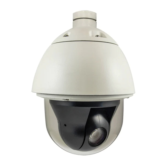
Hardware Manual Introduction List of Models This hardware manual contains the following model: PTZ Dome Network Camera, PoE-Plus 802.3af/at, 2-Megapixel, FCS-4042 Outdoor... -
Page 8: Package Contents
Hardware Manual Package Contents Check if the following items come with the camera package. If any of them is missing, please contact your local sales agents. Camera Power Cord Power Adapter Cable Gland Conduit Gland Gland Rubber Rings (x2) Hex Screwdriver Screws Universal Plugs Safety Strap... -
Page 9: Physical Description
Hardware Manual Physical Description 1) Reset Button The reset button is used to restore the factory default settings of the camera, including the administrator’s password. To reset the camera, do the following: a. Loosen the four (4) screws using the bundled hex screwdriver to remove the cover. b. - Page 10 Hardware Manual 5) Digital Input / Output The colored cables connect to digital input or output devices, such as an alarm trigger, panic button, etc. Digital Input (DI) and Digital Output (DO) devices are used for applications like motion detection, event triggering, alarm notifications, etc. Please refer to How to Connect Digital Input / Digital Output Devices on page 29 for information on how to connect DI/DO...
-
Page 11: Installation
Hardware Manual Installation Step 1: Unpack the Camera NOTE: To avoid scratches or leaving fingerprints on the dome cover, it is recommended to retain the plastic covering the dome cover until the camera is completely installed. However, the plastic has been removed on the pictures in this documentation to show clarity of the procedures being described. - Page 12 Hardware Manual 3. Remove the styrofoam and silicon bags from the camera. 4. Align the screw holes and tightly secure the screws using the bundled hex screwdriver.
-
Page 13: Step 2: Mount The Camera
Hardware Manual Step 2: Mount the Camera How to Mount the Outdoor PTZ Depending on the desired mounting solution, you may need to install the mounting solution first before connecting the cables or the cables may be connected first before installing the mounting solutions. - Page 14 Hardware Manual 3. Mount the camera 1. Align the gap on the camera to the tab inside the mounting solution and insert the camera through the mounting tube. 2. Attach the screws included in the camera package to secure the camera. 3.
- Page 15 Hardware Manual Below is an example of mounting the camera using pendant mount with the cables inside the ceiling.
-
Page 16: Step 3: Waterproof The Cable Connections
Hardware Manual Step 3: Waterproof the Cable Connections The camera itself is waterproof, however take note that the cable connections are not. If the camera is mounted directly on the ceiling/wall where the cables pass through the ceiling/wall, then your installation is complete and you do not need to waterproof the cable connections. -
Page 17: How To Waterproof The Cable Using The Cable Gland
Hardware Manual How to Waterproof the Cable Using the Cable Gland 1. Prepare the following items: Exterior-Grade Cable Gland Gland Rubber Ring Waterproof Tape Ethernet Cable NOTE: Not included NOTE: Not included in the camera in the camera package. package. 2. - Page 18 Hardware Manual 4. Insert the Ethernet cable through the sealing rubber and claw. 5. Attach one (1) supplied rubber ring on the gland body (smooth end). NOTE: Make sure the rubber ring is completely aligned on the gap on the gland body. 6.
- Page 19 Hardware Manual 7. Connect the Ethernet connector to the Ethernet port of the camera. 8. Insert the sealing rubber and claw into the cable gland body. 9. Attach the clamping nut to the cable gland body. Make sure the clamping nut is tightly secured and the rubber is squeezed in to avoid water leakage.
- Page 20 Hardware Manual 10. Arrange all unused cables and wrap them with the waterproof tape. NOTE: Different applications and installation environments require different types of waterproofing methods which may not be covered in this manual. Check your installation environment and adapt a suitable waterproofing method. ...
-
Page 21: How To Waterproof The Cable Using The Conduit Gland
Hardware Manual How to Waterproof the Cable Using the Conduit Gland 1. Prepare the following items: 1/2” Flexible Conduit Conduit Gland Gland Rubber Ring Waterproof Tape NOTE: Not included NOTE: Not included in the camera in the camera package. package. 2. - Page 22 Hardware Manual 4. Insert the sealing rubber and attach it at the end of the flexible conduit. 5. Attach one (1) supplied rubber ring on the gland body (smooth end). NOTE: Make sure the rubber ring is completely aligned on the gap on the gland body. 6.
- Page 23 Hardware Manual 7. Connect the Ethernet connector to the Ethernet port of the camera. 8. Insert the sealing rubber into the conduit gland body. 9. Attach the clamping nut to the conduit gland body. Make sure the clamping nut is tightly secured to avoid water leakage.
- Page 24 Hardware Manual 10. Arrange all unused cables and wrap them with the waterproof tape. NOTE: Different applications and installation environments require different types of waterproofing methods which may not be covered in this manual. Check your installation environment and adapt a suitable waterproofing method. ...
-
Page 25: How To Use The Junction Box
Hardware Manual How to Use the Junction Box When the camera is mounted with the cable connections exposed, use the PMAX-0700 Junction Box (not included in the package) to house the cable connections. 1. Place all the cables and the power adapter (if using one) inside the junction box. - Page 26 Hardware Manual 3. Secure the flex conduit fitting onto the junction box hole. NOTE: The PMAX-0700 Junction Box is not a bundled accessory. Contact your sales agents to purchase. 4. When using the bundled power adapter, do the following: a. Slide the voltage switch to set the adapter voltage according to the voltage standard in your location.
- Page 27 Hardware Manual Below is an example of the installing the camera using the Heavy Duty Wall Mount and Junction Box.
-
Page 28: Step 4: Connect The Equipment
Hardware Manual Step 4: Connect the Equipment How to View the Camera on Your PC Perform the following connections to view the camera from your PC: 1. Connect the camera and the PC to the same network using Ethernet cables. 2. -
Page 29: Other Connections And Accessories
Hardware Manual Other Connections and Accessories How to Connect Digital Input / Digital Output Devices Depending on your surveillance needs, you may need to connect digital input or output devices to your camera to trigger events or notifications. Digital Input (DI) devices can be used to notify the camera about an activity in the camera site. DI can be triggers of events. - Page 30 Hardware Manual Understanding the DI/DO Cables You can connect up to four (4) DI and two (2) DO devices to your camera. Digital Input Cables Cable Color Wiring Connection To connect digital input devices, map the DI Ground Pin (GND) Black device wires to the following: ...
- Page 31 Hardware Manual The table below shows the DI/DO connection specifications: Device Connection design TTL - compatible logic levels To trigger (low) Logic level 0: 0V ~ 0.4V Voltage Normal (high) Logic level 1: 3.1V ~ 30V Current 10mA ~ 100mA Connection design Transistor (Open Collector) Voltage &...
- Page 32 Hardware Manual Alarm Button (DI1 Device) 12V DC Speaker (DO1 Device) Outdoor PTZ 12V DC LED Infrared Sensor (DO2 Device) (DI2 Device) High Voltage DO Device Connection Even though the camera provides 12V power, this may not be enough for some high voltage DO devices, such as a ceiling light or a motor that opens or closes a gate.
- Page 33 Hardware Manual The illustration below is a graphic example of connecting a relay to a high voltage DO device. 110V-220V AC External Power Source Relay (DO1 Device) Outdoor PTZ Illuminator Note: For more information on DI/DO connections, please refer to the Knowledge Base article on our website.
-
Page 34: How To Use The Power Adapter
Hardware Manual How to Use the Power Adapter 1. Slide the voltage switch to set the adapter voltage according to the voltage standard in your location. 2. Connect the power cord to the power adapter. 3. Connect the power connector of the camera to the cable connector of the adapter. Power Adapter Camera Side Side... - Page 35 Hardware Manual 2. Remove the main fuse from its bay and pull to retrieve the replacement fuse. Main Fuse Replacement Fuse 3. Push the replacement fuse onto its bay. 4. Insert the fuse holder back into the power adapter and push until it locks into place.
-
Page 36: How To Attach The Safety Wire Strap
Hardware Manual How to Attach the Safety Wire Strap Most mounting accessories have a safety screw where the bundled safety wire strap can be used as additional protection to avoid dropping the camera while mounted on the high ceilings, etc. To attach the safety wire strap, do the following: 1. - Page 37 Hardware Manual 4. Align the bigger end of the safety wire strap on the mounting solution and then tightly attach the screw to lock the safety wire strap in place.
-
Page 38: How To Replace The Dome Cover
Hardware Manual How to Replace the Dome Cover The original dome cover that comes with the camera is Vandal Resistant (IK09). The dome cover can be replaced with a transparent or smoke Vandal Proof (IK10) dome cover available for purchase. To replace the dome cover, do the following: 1. - Page 39 Hardware Manual 4. Attach the dome cover to the camera by securing the screw through the wire strap. 5. Tighten the four (4) screws to close the dome cover.
-
Page 40: Accessing The Camera
Hardware Manual Accessing the Camera Configure the IP Addresses In order to be able to communicate with the camera from your PC, both the camera and the PC have to be within the same network segment. In most cases, it means that they both should have very similar IP addresses, where only the last number of the IP address is different from each other. - Page 41 Hardware Manual If you work with our cameras regularly, then there is even a better way to discover the cameras in the network – by using IP Utility. The IP Utility is a light software tool that can not only discover the cameras, but also list lots of valuable information, such as IP and MAC addresses, serial numbers, firmware versions, etc, and allows quick configuration of multiple devices at the same time.
- Page 42 Hardware Manual Use the default IP address of the camera If there is no DHCP server in the given network, the user may have to manually assign the IP addresses to both the PC and the camera to make sure they are in the same network segment. When the camera is plugged into the network and it does not detect any DHCP services, it will automatically assign itself a default IP: 192.168.0.100...
-
Page 43: Access The Camera
Hardware Manual Manually adjust the IP addresses of multiple cameras If there are more than one camera to be used in the same local area network and there is no DHCP server to assign unique IP addresses to each of them, all of the cameras would then have the initial IP address of 192.168.0.100, which is not a proper situation for network devices –... - Page 44 Hardware Manual You can use any of the browsers to access the camera, however, the full functionality is provided only for Microsoft Internet Explorer. The browser functionality comparison: Functionality Internet Explorer Other browsers Live Video Live Video Area Resizable PTZ Control Capture the snapshot Video overlay based configuration (Motion Detection regions, Privacy Mask regions)
- Page 45 Hardware Manual Assuming that the camera’s IP address is 192.168.0.100, you can access it by opening the Web browser and typing the following address into Web browser’s address bar: http://192.168.0.100 Upon successful connection to the camera, the user interface called Web Configurator would appear together with the login page.
- Page 46 Hardware Manual To check the firmware version through the Web Configurator, access the Setup page and click System > System Info. For further operations, please refer to the Firmware User Manual.