Table of Contents
Advertisement
Quick Links
Advertisement
Table of Contents

Related Manuals for LevelOne FCS-5061


Summary of Contents for LevelOne FCS-5061
- Page 1 FCS-5061 Day/Night 5-Megapixel PoE Plus Outdoor Network Camera User Manual Ver1.0...
-
Page 2: Table Of Contents
Table of Contents Overview ............................5 Features ........................5 Package Contents ....................... 6 Dimensions ........................7 Connectors ........................8 Camera Cabling ......................... 10 Connect Power ......................10 Connect Ethernet Cable .................... 11 Connect Alarm I/O ..................... 11 Installation ..........................12 Ceiling/Wall Mounting .................... - Page 3 6.3.9 Motion Detection ....................... 50 6.3.10 Network Failure Detection ..................56 6.3.11 Tampering ......................... 58 6.3.12 Storage Management (Local Recording) ..............61 6.3.13 Recording (Local Recording) ..................63 6.3.14 File Location (Snapshots and Web Recording) ............64 6.3.15 View Information ......................65 6.3.15.1 Log File ........................
- Page 4 Default ID / Password Login ID Password root...
-
Page 5: Overview
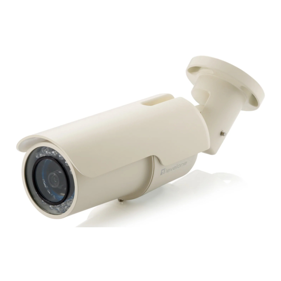
1. Overview Levelone FCS-5061 Day/Night 5-Megapixel PoE Plus Outdoor Camera is designed for flexible surveillance installation under the most demanding weather conditions. This camera is installation ready with an IP66-rated weather proof and vandal proof outdoor enclosure, built-in heater and IR LEDs for -40°C to 50°C harsh environments 24 hours surveillance. -
Page 6: Package Contents
1.2 Package Contents Please check the package contains the following items listed below. FCS-5061 POI-3002 (PoE Plus Injector) Camera Sunshield Camera Bracket Desiccant Pack Power Terminal Block Alarm Terminal Block M4 Inner Hex Wrench ... -
Page 7: Dimensions
1.3 Dimensions The IP Camera's dimensions are shown below... -
Page 8: Connectors
1.4 Connectors The Camera is equipped with an all-in-one cable for quick wiring. Definition for each connector are as follows. All-in-one Cable Cable Pin No. Definition Remarks Network (with POE) RJ-45 connector with LED AC 24V-1 Power Power connection AC 24V-2 ALM_DI-... - Page 9 Micro SD Card Slot/ Reset Button Follow the steps below to reach the Micro SD Card Slot, Reboot Button and Factory Default Button on the IP Camera: Step 1: Unscrew two screws on the Sun Shield to remove it. NOTE: Please note that the Sun Shield is optional.
-
Page 10: Camera Cabling
2. Camera Cabling Please follow the instructions below to complete Camera connection 2.1 Connect Power To power up the IP Camera, please plug the AC 24V cable into the Camera’s power terminal block. Alternatively, connect the Ethernet cable to the camera’s PoE port and plug the other end of the cable into a PoE switch. -
Page 11: Connect Ethernet Cable
2.2 Connect Ethernet Cable Use of Category 5 Ethernet cable is recommended for network connection; to have best transmission quality, cable length shall not exceed 100 meters. Connect one end of the Ethernet cable to the RJ-45 connector of the Camera, and the other end of the cable to the network switch or PC. -
Page 12: Installation
3. Installation Please read the instructions provided in this chapter thoroughly before installing the Camera. 3.1 Ceiling/Wall Mounting The IR Bullet IP Camera can be installed directly on a wall or ceiling with the integrated 2-axis adjustable Bracket Mount. Please note that the wall or ceiling must have enough strength to support the IP Camera. -
Page 13: System Requirements
4. System Requirements To perform the IP Camera via web browser, please ensure your PC is in good network connection, and meet system requirements as described below. Items System Requirement ○ ○ 1. Intel Pentium M, 2.16 GHz or ○ Intel Core 2 Duo, 2.0 GHz... -
Page 14: Accessing Camera
5. Accessing Camera For initial access to the IP Camera, users can search the camera through the installer program: DeviceSearch.exe, which can be found in “DeviceSearch” folder in the supplied CD. Device Search Software Setup Step 1: Double click on the program Device Search.exe (see the icon below); its window will appear as shown below. - Page 15 Device Search Step 3: Click “Device Search” again, and all the finding IP devices will be listed in the page, as shown in the figure below. The IP Camera’s default IP address is: 192.168.0.250. Step 4: Double click or right click and select “Browse” to access the camera directly via web browser.
- Page 16 The default login ID and password for the Administrator are: Login ID Password root NOTE: ID and password are case sensitive. NOTE: It is strongly advised that administrator’s password be altered for the security concerns. Additionally, users can change the IP Camera’s network property, either DHCP or Static IP directly in the device finding list.
- Page 17 Step 2: The “Network Setup” page will come out. Select “DHCP,” and press “Apply” button down the page. Step 3: Click “OK” on the Note of setting change. Wait for one minute to re-search the IP Camera. Step 4: Click the “Device Search” button to re-search all the devices. Then select the IP Camera with the correct MAC address.
-
Page 18: Using Recording Software
5.1 Using Recording Software The product software CD also contains recording software-IP CamSecure, allowing simultaneous monitoring and video recording for multiple Network Cameras. Please install the recording software; then launch the program to add the Network Camera to the Channel list. -
Page 19: Installing Dc Viewer Software Online
5.2 Installing DC Viewer Software Online For the initial access to the IP Camera, a client program, DC Viewer, will be automatically installed to your PC when connecting to the IP Camera. If the Web browser doesn’t allow DC Viewer installation, please check the Internet security settings or ActiveX controls and plug-ins settings (see Appendix B: Internet Security Settings... - Page 20 Once login to the IP Camera, users will see the Home page as shown below:...
-
Page 21: Configuration & Operation
6. Configuration & Operation The IP Camera is provided with a user-friendly browser-based configuration interface, and a free bundled CMS (Central Management System) for video playback and recording. In this chapter, information about main page introduction, system related settings and camera settings will be described in detail. - Page 22 There are five tabs: Home, System, Streaming, Camera and Logout on the top panel. Home Users can monitor live video of the targeted area. System setting The administrator can set host name, system time, root password, network related settings, etc. Streaming setting The administrator can modify video resolution and rotate type and select audio compression mode in this page.
-
Page 23: Home Page
6.2 Home Page Click on the tab <Home> to access the Home Page. There are several function buttons on the Home page. Detailed information of each item is as described in the following chapter. NOTE: Please note that the function buttons will vary depending on the camera model. - Page 24 NOTE: This function is only available for the Box Camera and Vandal Proof IP Dome. Speaker button (on/off) Press the Speaker button to mute/activate the audio. NOTE: This function is only available for User who has granted this privilege by the Administrator . Snapshot button Press the button, and the JPEG snapshots will automatically be saved in the appointed place.
-
Page 25: System Related Settings
6.3 System Related Settings Under the tab <System>, there are submenus including: <System>, <Security>, <Network>, <DDNS>, <Mail>, <FTP>, <HTTP>, <Application>, <Motion Detection>, <Network Failure Detection>, <Tampering>, <Storage Management>, <Recording>, <File Location>, <View Information>, <Factory Default>, <Software Version>, <Software Upgrade>, and <Maintenance>. NOTE: The “System”... -
Page 26: Host Name And System Time Setting
6.3.1 Host Name and System Time Setting Press the first category: <System> in the left column; the page is shown as below. Host Name The name is for camera identification. If alarm function (see section Application is enabled and is set to send alarm message by Mail/FTP, the host name entered here will display in the alarm message. -
Page 27: Security
Sync With Computer Time Select the item, and video date and time display will synchronize with the PC’s. Manual The Administrator can set video date, time and day manually. Entry format should be identical with that shown next to the enter field. Sync with NTP Server Network Time Protocol (NTP) is an alternate way to synchronize your camera’s clock with a NTP server. -
Page 28: User
6.3.2.1 User The User setting can be found under this path: System> Security> User. Admin password Change the administrator’s password by inputting the new password in “Admin password” and “Confirm password” text boxes. The input characters/numbers will be displayed as dots for security purposes. After clicking on <Save>, the web browser will ask the Administrator for the new password for accessing. - Page 29 I/O access This item supports fundamental functions that enable users to view video when accessing to the camera. Camera control This item allows the appointed User to change camera parameters on the Camera Setting page. Talk/Listen Talk and Listen functions allow the appointed user in the local site (PC site) communicating with, for instance, the administrator in the remote site.
-
Page 30: Https
6.3.2.2 HTTPS The HTTPS setting can be found under this path: System> Security> HTTPS. <HTTPS> allows secure connections between the IP Camera and web browser using <Secure Socket Layer (SSL)> or <Transport Layer Security (TLS)>, which ensure camera settings or Username/ Password info from snooping. It is required to install a self-signed certificate or a CA-signed certificate for implementing <HTTPS>. - Page 31 Click on <Create> button under “Create self-signed certificate” and provide the requested information to install a self-signed certificate for the IP Camera. Please refer to the last part of this section: Provide the Certificate Information for more details. NOTE: The self-signed certificate does not provide the same high level of security as when using a CA-issued certificate.
-
Page 32: Ip Filter
6.3.2.3 IP Filter The IP Filter setting can be found under this path: System> Security> IP Filter. Using the IP filter, access to the IP Camera can be restricted by denying/allowing specific IP addresses. Enable IP Filter Check the box to enable the IP Filter function. Once enabled, the listed IP addresses (IPv4) will be allowed/ denied access to the IP Camera. -
Page 33: Ieee 802.1X
6.3.2.4 IEEE 802.1X The IEEE 802.1X setting can be found under this path: System> Security> IEEE 802.1X. The IP Camera is allowed to access a network protected by 802.1X/EAPOL (Extensible Authentication Protocol over LAN). Users need to contact with the network administrator for gaining certificates, user IDs and passwords CA Certificate The CA certificate is created by the Certification Authority for the purpose of... - Page 34 Settings Identity Enter the user identity associated with the certificate. Up to 16 characters can be used. Private Key Password Enter the password (maximum 16 characters) for your user identity. Enable IEEE 802.1X Check the box to enable IEEE 802.1X. Click on <Save>...
-
Page 35: Network
6.3.3 Network The Network setting can be found under this path: System> Network. Click on the <Network> category, there will be a drop-down menu with tabs including <Basic>, <QoS>, <SNMP>, and <UPnP>. -
Page 36: Basic
6.3.3.1 Basic The Basic setting can be found under this path: System> Network> Basic. Users can choose to connect to the IP Camera with fixed or dynamic (DHCP) IP address. The IP Camera also provides PPPoE support for users who connect to the network via PPP over Ethernet (PPPoE). - Page 37 Use fixed IP address To setup static IP address, select <Use fixed IP address> and move the cursor to the IP address blank and insert the new IP address, ex. 192.168.7.123; then go to the Default gateway (explained later) blank and change the setting, ex. 192.168.7.254.
- Page 38 Administrator changes the HTTP port of the IP Camera whose IP address is 192.168.0.100 from 80 to 8080, the user must type in the web browser “http://192.168.0.100:8080” instead of “http://192.168.0.100”. RTSP port The default setting of RTSP Port is 554; the setting range is from 1024 to 65535. MJPEG over HTTP port The default setting of MJPEG over HTTP Port is 8008;...
-
Page 39: Qos
6.3.3.2 The QoS (Quality of Service) setting can be found under this path: System> Network> QoS. QoS allows providing differentiated service levels for different types of traffic packets, which guarantees delivery of priority services especially when network congestion occurs. Adapting the Differentiated Services (DiffServ) model, traffic flows are classified and marked with DSCP (DiffServ Codepoint) values, and thus receive the corresponding forwarding treatment from DiffServ capable routers. - Page 40 RTSP/HTTP. Audio DSCP This setting is only available for the IP Cameras that support audio. Management DSCP The class consists of HTTP traffic: Web browsing. NOTE: To enable this function, please make sure the switches/ routers in the network support QoS.
-
Page 41: Snmp
6.3.3.3 SNMP The SNMP (Simple Network Management Protocol) setting can be found under this path: System> Network> SNMP. With Simple Network Management Protocol (SNMP) support, the IP Camera can be monitored and managed remotely by the network management system. SNMP v1/ v2 Enable SNMP v1/ v2 Select the version of SNMP to use by checking the box. - Page 42 objects (except read-only objects). The default value is “write”. Traps for SNMP v1/ v2 Traps are used by the IP Camera to send massages to a management system for important events or status changes. Enable Traps Check the box to activate trap reporting. Trap address Enter the IP address of the management server.
-
Page 43: Upnp
6.3.3.4 UPnP The UPnP setting can be found under this path: System> Network> UPnP. UPnP Setting Enable UPnP When the UPnP is enabled, whenever the IP Camera is presented to the LAN, the icon of the connected IP Cameras will appear in My Network Places to allow for direct access. - Page 44 open the web server port on the router automatically. NOTE: To enable this function, please make sure that your router supports UPnP and it is activated. Friendly name Set the name for the IP Camera for identity.
-
Page 45: Ddns
6.3.4 DDNS The DDNS setting can be found under this path: System> DDNS. Dynamic Domain Name System (DDNS) allows a host name to be constantly synchronized with a dynamic IP address. In other words, it allows those using a dynamic IP address to be associated to a static domain name so others can connect to it by name. -
Page 46: Mail
6.3.5 Mail The Mail setting can be found under this path: System> Mail. The Administrator can send an e-mail via Simple Mail Transfer Protocol (SMTP) when event is triggered. SMTP is a protocol for sending e-mail messages between servers. SMTP is a relatively simple, text-based protocol, where one or more recipients of a message are specified and the message text is transferred. -
Page 47: Ftp
6.3.6 The FTP setting can be found under this path: System> FTP. The Administrator can set as sending alarm message to a specific File Transfer Protocol (FTP) site when event is triggered. Users can assign alarm message to up to two FTP sites. Enter the FTP details, which include server, server port, user name, password and remote folder, in the fields. -
Page 48: Http
6.3.7 HTTP The HTTP setting can be found under this path: System> HTTP. A HTTP Notification server can listen for notification messages from IP Cameras by triggered events. Enter the HTTP details, which include server name (for instance, http://192.168.0.1/admin.php), user name, and password in the fields. <Alarm>... -
Page 49: Application
5.3.8 Application The IP Camera equips one alarm input and one relay output for cooperating with alarm system to catch events’ images. Refer to alarm pin definition below to connect alarm devices to the IP Camera if needed. The alarm configuration page is also shown below. - Page 50 Enable Alarm Output Select the item to enable alarm relay output. IR Cut Filter Select the item and the camera’s IR cut filter (ICR) will be removed (on) or blocked (off) when alarm input is triggered. Note: The IR Function (Refer to IR Function) could not be set as <Auto>...
- Page 51 Upload Image by E-Mail Select this item, and the Administrator can assign an e-mail address and configure various parameters as shown in the figure below. When the alarm is triggered, event images will be sent to the appointed e-mail address. <Pre-trigger buffer>...
- Page 52 happened to cause the trigger. The pre-trigger buffer time range is from 1 to 3 seconds. Select <Upload for __sec> to set the recording duration after alarm is triggered. The setting range is from 1 to 99999 seconds. Select <Upload during the trigger active> to record the triggered video until the trigger is off.
-
Page 54: Motion Detection
6.3.9 Motion Detection The Motion Detection setting can be found under this path: System> Motion Detection. Motion Detection function allows detecting suspicious motion and triggering alarms when motion volume in the detected area reaches/exceeds the determined sensitivity threshold value. In the Motion Detection setting page, there is a frame (Motion Detection Window) displayed on the Live View Pane. - Page 55 Up 10 Motion Detection Windows can be set. Press the “add” button under the Live View Pane to add a Motion Detection Window. To cancel a Motion Detection Window, move the mouse cursor to the selected Window, and click on the “delete” button. If Motion Detection function is activated, the pop-off window (Motion) with indication of motion will be shown.
- Page 56 Motion Detection You will be able to turn on/off Motion Detection in System section. Default setting is Off. Motion Detection Setting Users could adjust various parameters of Motion Detection in this section. Sampling pixel interval [1-10]: The default value is 1. If the value is set as 3, it means within the detection region, system will take one sampling pixel for every 3 pixels by each row and each column (refer to the figure below).
- Page 57 Record stream to SD Card Select this item and the Motion Detection recording will be stored in Micro SD/ SDHC card when motion is detected. Pre-trigger buffer recording function allows users to check what happened to cause the trigger. The pre-trigger buffer time range is from 1 to 3 seconds. Select <Upload for __ sec>...
- Page 58 Upload Image by E-Mail Select this item and the Administrator can assign an e-mail address and configure various parameters. When motion is detected, event images will be sent to the appointed e-mail address. <Pre-trigger buffer> function allows users to check what happened to cause the trigger.
- Page 59 H: Hour, N: Minute, S: Second X: Sequence Number Add sequence number suffix (no maximum value) File name: imageXXXXXXX.jpg X: Sequence Number Add sequence number suffix up to # and then start over File Name: imageXX.jpg X: Sequence Number The file name suffix will end at the number being set. For example, if the setting is up to “10,”...
-
Page 60: Network Failure Detection
6.3.10 Network Failure Detection Network Failure Detection allows the IP Camera to ping another IP device (e.g. NVR, VSS, Video Server, etc.) within the network periodically and generates some actions in case of network failure occurs, for instance, a Video Server is somehow disconnected. - Page 61 Select the item and the alarm-triggered recording will be saved into your Micro SD card. Pre-trigger buffer recording function allows users to check what happened to cause the trigger. The pre-trigger buffer time range is from 1 to 3 seconds. Select <Upload for __ sec> to set the recording duration after alarm is triggered.
-
Page 62: Tampering
6.3.11 Tampering The Tampering setting can be found under this path: System> Tampering. Tampering Alarm function helps the IP Camera against tampering such as deliberate redirection, blocking, paint spray, and lens cover, etc through video analysis and reaction to such events by sending out notifications or uploading snapshots to the specified destination(s). - Page 63 Triggered Action (Multi-option) The Administrator can specify alarm actions that will take when tampering is detected. All options are listed as follows: Enable Alarm Output Check the item and select the predefined type of alarm output to enable alarm output when tampering is detected. Record stream to SD Card Select this item and the Tampering Alarm recording will be stored in Micro SD/ SDHC card when tampering is detected.
- Page 64 NOTE: Make sure FTP configuration has been completed. Refer to FTP for further details Upload Image by E-Mail Select this item and the Administrator can assign an e-mail address and configure various parameters. When tampering is detected, event images will be sent to the appointed e-mail address. <Pre-trigger buffer>...
-
Page 65: Storage Management (Local Recording)
Add sequence number suffix up to # and then start over File Name: imageXX.jpg X: Sequence Number The file name suffix will end at the number being set. For example, if the setting is up to “10,” the file name will start from 00, end at 10, and then start all over again. - Page 66 To implement Micro SD card recording, please go to the <Recording> page (refer to Recording) for activation. NOTE: Please format the Micro SD/SDHC card when using for the first time. Formatting will also be required when a memory card already being used on one camera and later transferred to another camera with different software platform.
-
Page 67: Recording (Local Recording)
6.3.13 Recording (Local Recording) The Recording setting can be found under this path: System> Recording. In the Recording setting page, the Micro SD Card recording schedule supports up to ten sets of time frames. User can specify the recording schedule to fit the present surveillance requirement. -
Page 68: File Location (Snapshots And Web Recording)
Activating Micro SD/SDHC Card Recording Two types of schedule mode are offered: <Always> and <Only during Time Frame>. Users can select <Always> to activate Micro SD/SDHC Card Recording all the time. Or select a set of schedule from the time frame blank, check specific weekdays and setup the start time (hour:minute) and time period (hour:minute) to activate Micro SD/SDHC Card Recording at certain time frames. -
Page 69: View Information
NOTE: For users with Windows 7 operating system, it is required to log on as an Administrator to implement the Snapshot and Web Recording function. 6.3.15 View Information The View Information function can be found under this path: System> View Information. -
Page 70: Log File
6.3.15.1 Log File The Log File function can be found under this path: System> Log File. Click on the tab to view the system log file. The content of the file provides useful information about connections after system boot-up. -
Page 71: User Information
6.3.15.2 User Information The User Information function can be found under this path: System> User Information. The Administrator can view each added user’s login information and privileges (refer to Security). Get User Information All the users in the network will be listed in the <User information> zone. Get User Privacy Click on <get user privacy>... -
Page 72: Parameters
6.3.15.3 Parameters The Parameters function can be found under this path: System> Parameter. Click on this item to view the entire system’s parameter setting such as Camera Settings, Mask Information and Network Information. -
Page 73: Factory Default
6.3.16 Factory Default The Factory Default setting can be found under this path: System> Factory Default. Users can follow the instructions on this page to reset the IP Camera to factory default setting if needed. Set Default Click on the <Set Default> button to recall the factory default settings. Then the system will restart in 30 seconds. -
Page 74: Software Version
6.3.17 Software Version The Software Version can be found under this path: System> Software Version. The current software version is displayed in the software version page. -
Page 75: Software Upgrade
6.3.18 Software Upgrade The Software Version can be found under this path: System> Software Upgrade. NOTE: Make sure the upgrade software file is available before carrying out software upgrade. The procedure of software upgrade is as below: Step 1. Click on “Browse” and select the binary file to be uploaded, ex. uImage_userland. - Page 76 Step 3. Click on the <Upgrade> button. The system will check whether the upgrade file exists or not first, and then begin to upload the upgrade file. Subsequently, the upgrade status bar will display on the page. When it runs to 100%, the upgrade process is finished. After the upgrade process is finished, the viewer will return to Home page.
-
Page 77: Maintenance
6.3.19 Maintenance The Maintenance setting can be found under this path: System> Maintenance. Users can export configuration files to a specified location and retrieve data by uploading an existing configuration file to the IP Camera. Export Users can save the system settings by exporting the configuration file (.bin) to a specified location for future use. - Page 78 Upload To copy an existing configuration file to the IP Camera, please first click on “Browse” to select the configuration file, and then press the “Upload” button for uploading.
-
Page 79: Streaming
6.4 Streaming Under the tab <Streaming>, there are submenus including: <Video Format>, <Video Compression>, <Video ROI>, <Video OCX Protocol>, <Video Frame Rate>, <Video Mask>, and <Audio>. In the Streaming submenus, the Administrator can configure specific video resolution, video compression mode, video protocol, audio transmission mode, etc. -
Page 80: Video Resolution And Rotate Type
6.4.1 Video Resolution and Rotate Type The Video Format setting can be found under this path: Streaming> Video Format. Video Resolution Under Video Resolution section, the available video resolution formats are including MJPEG and H.264. Click on <Save> to confirm the setting. Text Overlay Settings Users can select the items to display data including date/time/text on the live video pane. - Page 81 types include Normal, Flip, Mirror, 90 degree clockwise, 180 degree rotate and 90 degree counterclockwise. The following is descriptions for different video rotate type. Flip If select <Flip>, the image will be rotated vertically. Mirror If select <Mirror>, the image will be rotated horizontally. 90 Degree counter-/clockwise Selecting <90 Degree Counter-/clockwise>...
-
Page 82: Video Compression
6.4.2 Video Compression The Video Compression setting can be found under this path: Streaming> Video Compression. MJPEG Q (Quality) factor Higher value implies higher bit rates and higher visual quality. The default setting of MJPEG Q factor is 35; the setting range is from 1 to 70. H.264-1/ H.264-2/ H.264-3/ H.264-4 bit rate The default setting of H.264-1 is 4096 kbit/s and for H.264-2/ H.264-3/ H.264-4 is 1024 kbit/s;... -
Page 83: Video Roi
CBR Mode Setting The CBR (Constant Bit Rate) mode could be the preferred bit rate mode if the bandwidth available is limited. It is important to take account of image quality while choosing to use CBR mode. Click on <Save> to confirm the setting. 6.4.3 Video ROI The Video ROI setting can be found under this path: Streaming>... - Page 84 Video ROI Setting Enable Stream 2 ROI Setting Check the box and Stream 2 ROI Window will be displayed. To change the size of Stream 2 ROI Window, move the mouse cursor to the edge of the frame and draw it outward/inward. Moving the mouse to the center of the frame can shift the frame to the intended location.
-
Page 85: Video Ocx Protocol
6.4.4 Video OCX Protocol The Video OCX Protocol setting can be found under this path: Streaming> Video OCX Protocol. In the Video OCX protocol setting page, users can select RTP over UDP, RTP over RTSP (TCP), RTSP over HTTP or MJPEG over HTTP for streaming video over the network. -
Page 86: Video Frame Rate
6.4.5 Video Frame Rate The Video Frame Rate setting can be found under this path: Streaming> Video Frame Rate. Video frame rate is for setting the frames per second (fps) if necessary. MJPEG/ H.264-1/ H.264-2/ H.264-3/ H.264-4 Frame Rate The default setting of MJPEG/H.264-1/H.264-2/ H.264-3/ H.264-4 Frame Rate is 30 fps;... -
Page 87: Video Mask
6.4.6 Video Mask The Video Mask setting can be found under this path: Streaming> Video Mask. Active Mask Function Add a Mask Check a Video Mask checkbox, and a red frame will come out in the Live Video pane at the right side. Use the mouse to drag and drop to adjust the mask’s size and place it on the target zone. -
Page 88: Audio (Audio Mode And Bit Rate Settings)
Mask Setting Mask color The selections of Mask color include red, black, white, yellow, green, blue, cyan, and magenta. Click on <Save> to confirm the setting. 6.4.7 Audio (Audio Mode and Bit Rate Settings) The Audio Mode setting can be found under this path: Streaming> Audio. In the Audio page, the Administrator can select one transmission mode and audio bit rate. - Page 89 NOTE: This option is only available for selected models. Half-duplex (Talk or Listen, not at the same time) In the Half-duplex mode, the local/remote site can only talk or listen to the other site at a time. NOTE: This option is only available for selected models. Simplex (Talk only) In the Talk only Simplex mode, the local/remote site can only talk to the other site.
-
Page 90: Camera Settings
Camera Settings The figure below is the camera configuration page. Details of each parameter setting are described in the following subsections. NOTE: Camera settings and function buttons may vary depending on the camera model. -
Page 91: Exposure Setting
6.5.1 Exposure Setting The Exposure Setting can be found under this path: Camera> Exposure. The exposure is the amount of light received by the image sensor and is determined by the width of lens diaphragm opening, the amount of exposure by the sensor (shutter speed) and other exposure parameters. -
Page 92: White Balance Setting
6.5.2 White Balance Setting The White Balance Setting can be found under this path: Camera> White Balance. A camera needs to find reference color temperature, which is a way of measuring the quality of a light source, for calculating all the other colors. The unit for measuring this ratio is in degree Kelvin (K). -
Page 93: Brightness Setting
6.5.3 Brightness Setting The Picture Adjustment can be found under this path: Camera> Picture Adjustment. Brightness Users can adjust the image’s brightness by adjusting the item. Please select ranging from -12 to +13. To increase video brightness, select a bigger number. Click on <√... -
Page 94: Backlight
6.5.4 Backlight The Backlight Setting can be found under this path: Camera> Backlight. The Backlight Compensation function prevents the center object from being too dark in surroundings where excessive light is behind the center object. Click on < √ > to confirm the new setting. 6.5.5 Digital Zoom The Digital Zoom Setting can be found under this path: Camera>... -
Page 95: Wdr Function
Additionally, for the models with built-in IR LED module, the day/night IR switching mechanism will depends on the ambient light level instead of the light sensor (Light sensor mode) on the IR LED module. Click on <√> to confirm the new setting. 6.5.7 WDR Function The WDR Function Setting can be found under this path: Camera>... -
Page 96: Tv System Setup
6.5.9 TV System Setup The TV System Setting can be found under this path: Camera> TV System. Select the video format that matches the present TV system. Click on < √ > to confirm the new setting. Logout Press the tab “Logout” in the top of the page, and the login window will pop up. This enables login with another user name. -
Page 97: Appendix A: Technical Specifications
Appendix A: Technical Specifications FCS-5061 Image Sensor 1/2.5” 5MP Progressive Scan CMOS Effective Pixels 2592(H) x 1944(V) 0.1 Lux / F1.5 (Without IR LED ) Minimum Illumination 0 Lux / F1.5 ( With IR LED ) White Balance Manual / AWB/ ATW Shutter Speed 1~ 1/30000 sec. - Page 98 IPv4/v6, TCP/IP, UDP, RTP, RTSP, HTTP, HTTPS, ICMP, FTP, SMTP, Protocol DHCP, PPPoE, UPnP, IGMP, SNMP, QoS, ONVIF Security HTTPS / IP Filter / IEEE 802.1x 1 Set; 5V 10kΩ pull up Input Alarm Output 1 Set; Photo Relay Output 300V DC/AC Event Notification HTTP / FTP / SMTP Micro SD...
-
Page 99: Appendix B: Internet Security Settings
Appendix B: Internet Security Settings If ActiveX control installation is blocked, please either set Internet security level to default or change ActiveX controls and plug-ins settings. Internet Security Level: Default Step 1: Start the Internet Explorer (IE). Step 2: Select <Tools> from the main menu of the browser. Then Click <Internet Options>. Step 3: Click the <Security>... - Page 100 Step 4: Down the page, press “Default Level” (see the figure above) and click “OK” to confirm the setting. Close the browser window, and open a new one later when accessing the IP Camera. ActiveX Controls and Plug-ins Settings Step 1~3: Refer to the previous section above. Step 4: Down the page, press “Custom Level”...
- Page 101 The Security Settings screen is displayed as below: Step 5: Under “ActiveX controls and plug-ins”, set ALL items (as listed below) to <Enable> or <Prompt>. ActiveX controls and plug-ins settings: 1. Automatic prompting for ActiveX controls 2. Binary and scrip behaviors 3.
-
Page 102: Appendix C: Dc Viewer Download Procedure
Appendix C: DC Viewer Download Procedure The procedure of DC Viewer software download is specified as follows. Step 1: In the DC Viewer installation page, click “Next” for starting installing. Step 2: Setup starts. Please wait for a while until the loading bar runs out. - Page 103 Step 3: Click “Finish” to close the DC Viewer installation page. Then, the IP Camera’s Home page will display as follows:...
-
Page 104: Appendix D: Install Upnp Components
Appendix D: Install UPnP Components Please follow the instructions below to install UPnP components. Step 1: Go to “Start”, click on “Control Panel”, and then double click “Add or Remove Programs”. Step 2: Click on “Add/Remove Windows Components” in the Add or Remove Programs page.. - Page 105 Step 3: Select “Networking Services” from the Components list in the Windows Components Wizard window, and then click “Details”. Step 4: Select “UPnP User Interface” in the Networking Services’ subcomponents list and then click “OK”.
- Page 106 Step 5: Click “Next” in the Windows Components Wizard page. Step 6: Click “Finish” to complete installation.