Table of Contents
Advertisement
Quick Links
Advertisement
Table of Contents

Related Manuals for LevelOne FCS-4041


Summary of Contents for LevelOne FCS-4041
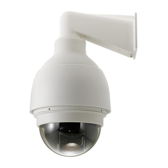
- Page 1 FCS-4041 Day/Night H.264 2-Megapixel PoE IP Dome Camera User Manual Ver1.0...
-
Page 2: Table Of Contents
Table of Contents Overview ...........................4 Features ........................4 Package Contents ......................5 Dimensions........................6 Switch/Connector Definition ..................7 Camera Cabling........................8 Connect Power......................8 Connect Ethernet Cable ....................8 Apply Alarm I/O ......................9 Apply Audio ........................9 System Requirements ......................10 Access Camera ........................ - Page 3 7.2.20 Maintenance ....................56 Streaming........................57 7.3.1 Video Format (Video Resolution/ Video Deinterlace) ........57 7.3.2 Video Compression ..................60 7.3.3 Video OCX Protocol..................61 7.3.4 Video Frame Rate..................62 7.3.5 Audio (Audio Mode and Bit Rate Settings)............63 PTZ..........................64 7.4.1 Preset ......................64 7.4.2 Cruise ......................65 7.4.3 Auto Pan .......................66 7.4.4 Sequence .....................67...
-
Page 4: Overview
1. Overview The Full HD Speed Dome IP Camera transmits digital video and audio data using wire connection. Live video can be monitored and recorded from window-based computer via network. The video encoder supports real-time Main Profile H.264 Full HD resolution. Simultaneous dual streams, H.264/H.264 and H.264/MJPEG, are available for various network applications via speeding or limited bandwidth. -
Page 5: Package Contents
Package Contents Please check the box contains the items listed here. If any item is missing or has defects, DO NOT install or operate the product and contact your dealer for assistance. Outdoor Dome Camera Package M3 Standard Screw (x1) M3 Security Screw (x1)☆... -
Page 6: Dimensions
Dimensions Outdoor... -
Page 7: Switch/Connector Definition
Switch/Connector Definition There are various connectors located on the Dome Camera’s back plate as shown in the figures below. Please refer to the diagrams and tables accompanied with for use of each switch/connector. Outdoor RJ-45 Connector ALARM I/O Power Micro SD Card Slot Factory Reset Button Audio I/O NOTE: DO NOT change the network Speed Dome Camera’s... -
Page 8: Camera Cabling
Camera Cabling Please follow the instructions below to complete network Speed Dome Camera connection. Connect Power Please refer to the illustrations below to connect power core through the supplied power adaptor. Definition AC 24_1 AC 24_2 Connect Ethernet Cable Use of Category 5 Ethernet cable is recommended for network connection; to have best transmission quality, cable length shall not exceed 100 meters. -
Page 9: Apply Alarm I/O
Apply Alarm I/O The network Speed Dome Camera supports 4 digital alarm inputs and 2 digital alarm outputs. Please make sure the alarm connections are properly wired before starting to configure alarm related settings on this “Application” page. Please refer to the pin definition table below for alarm system wiring. Definition Definition ALARM_OUT_NO_1... -
Page 10: System Requirements
System Requirements To perform the network Speed Dome Camera via web browser, please ensure your PC is in good network connection, and meet system requirement as described below. Items Minimum Requirement ® ® ® 1. Intel Pentium IV, 3 GHz or higher, Intel Core2 Duo, 2 GHz or higher Personal Computer... -
Page 11: Access Camera
Access Camera For initial access to the network Speed Dome Camera, users can search the camera through the installer program: DeviceSearch.exe, which can be found in “Device Search” folder in the supplied CD. Device Search Software Setup Step 1: Double click on the program Device Search.exe. After its window will appear, click on the <Device Search>... - Page 12 Additionally, users can change the network Speed Dome Camera’s network property, either DHCP or Static IP directly in the device finding list. Refer to the following section for changing the network Speed Dome Camera’s network property. Example of Changing IP Camera’s Network Property Users can directly change a Network Speed Dome Camera’s network property, ex.
- Page 13 The Information Bar (just below the URL bar) may come out and ask for permission to install the ActiveX Control for displaying video in browser. Right click on the Information Bar and select <Install ActiveX Control…> to allow the installation. Then the security warning window will pop up. Click on <Install> to carry on software installation.
-
Page 14: Setup Video Resolution
Setup Video Resolution Users can setup Video Resolution on Video Format page of the user-friendly browser-based configuration interface. Video Format can be found under this path: Streaming> Video Format. - Page 15 Video Format Under Video Resolution section, select a preferred resolution setting. The available Video Resolution for MJPEG & H.264 format includes: MJPEG+ H.264 MJPEG H.264 BNC SUPPORT √ 720 x 480 (30fps)* √ 1920 x 1080 (30fps) 640 x 480 (30fps) √...
- Page 16 √ 640 x 480 (30fps) 640 x 480 (30fps) √ 352 x 240 (30fps) H.264 + H.264 H.264-1 H.264-2 BNC SUPPORT √ 720 x 480 (30fps)* √ 1920 x 1080 (30fps) 640 x 480 (30fps) √ 352 x 240 (30fps) √...
- Page 17 √ 640 x 480 (30fps) 640 x 480 (30fps) √ 352 x 240 (30fps) MJPEG ONLY MJPEG BNC SUPPORT √ 1920 x 1080 (30fps) √ 1280 x 1024 (30fps) √ 1280 x 720 (30fps) √ 1024 x 768 (30fps) √ 800 x 600 (30fps) √...
-
Page 18: Overview
Overview The Full HD Speed Dome IP Camera transmits digital video and audio data using wire connection. Live video can be monitored and recorded from window-based computer via network. The video encoder supports real-time Main Profile H.264 Full HD resolution. Simultaneous dual streams, H.264/H.264 and H.264/MJPEG, are available for various network applications via speeding or limited bandwidth. -
Page 19: Home Page
Home Page Click on the tab <Home> to access the Home Page. There are several function buttons on the Home pate. Detailed information of each item is as described in the following chapter. 7.1.1 Function Items on Home Page Multiple Languages Support Multiple languages are supported, including German, English, French, Italian, Korean, Simplified Chinese, Russian, etc. - Page 20 Talk function allows the local site talks to the remote site. Click on the button to switch it to on/off. Please refer to Security: Add user >> Talk/Listen for further details. NOTE: This function is only available for User who has granted this privilege by the Administrator.
- Page 21 Near/Far buttons. Near/Far buttons Click on the <Manual> button, and users can adjust focus manually via <Near> and <Far> buttons. The status will also be displayed above the screen as shown below Pan/Tilt Control Users can implement pan/tilt control by first moving the cursor to the live video pane;...
-
Page 22: System
System Under the tab <System>, there are categories as the table below: System Security Network DDNS Mail FTP HTTP Application Motion Detection Tampering Storage Management System Recording File Location View Log File View User Information View Parameters Factory Default Software Version Software Upgrade Maintenance NOTE: The System configuration page is only accessible by the... - Page 23 Time Zone Select the time zone you are in from the drop-down menu. Enable Daylight Saving Time To enable DST, please check the item and then specify time offset and DST duration. The format for time offset is [hh:mm:ss]; for instance, if the amount of time offset is one hour, please enter “01:00:00”...
-
Page 24: Security
Sync with NTP Server Network Time Protocol (NTP) is an alternate way to synchronize your camera’s clock with a NTP server. Please specify the server you wish to synchronize in the enter field. Then select an update interval from the drop-down menu. For further information about NTP, please see the web site: www.ntp.org. - Page 25 I/O access This item supports fundamental functions that enable users to view video when accessing to the camera. Camera control This item allows the appointed User to change camera parameters on the Camera Setting page. Talk/Listen Talk and Listen functions allow the appointed user in the local site (PC site) communicating with, for instance, the administrator in the remote site.
- Page 26 7.2.2.2 HTTPS The HTTPS setting can be found under this path: System> Security> HTTPS. <HTTPS> allows secure connections between the IP Camera and web browser using <Secure Socket Layer (SSL)> or <Transport Layer Security (TLS)>, which ensure camera settings or Username/ Password info from snooping. It is required to install a self-signed certificate or a CA-signed certificate for implementing <HTTPS>.
- Page 27 certificate. Provide the Certificate Information To create a Self-signed HTTPS Certificate or a Certificate Request to CA, please enter the information as requested: Create Self Signed Certificate Create Certificate Request √ √ Country √ √ State or Province √ √ Locality √...
- Page 28 7.2.2.3 IP Filter The IP Filter setting can be found under this path: System> Security> IP Filter. Using the IP filter, access to the IP Camera can be restricted by denying/allowing specific IP addresses. Enable IP Filter Check the box to enable the IP Filter function. Once enabled, the listed IP addresses (IPv4) will be allowed/ denied access to the IP Camera.
- Page 29 Add/ Delete IP Address Input the IP address and click on the <Add> button to add a new filtered address. The Filtered IP Addresses list box shows the currently configured IP addresses. Up to 256 IP address entries may be specified. To remove an IP address from the list, please select the IP and then click the <Delete>...
- Page 30 Check the box to enable IEEE 802.1X. Click on <Save> to save the IEEE 802.1X/ EAP- TLS setting.
-
Page 31: Network
7.2.3 Network The Network setting can be found under this path: System> Network. Click on the <Network> category, there will be a drop-down menu with tabs including <Basic>, <QoS>, <SNMP>, and <UPnP>. 7.2.3.1 Basic The Basic setting can be found under this path: System> Network> Basic. Users can choose to connect to the IP Camera with fixed or dynamic (DHCP) IP address. - Page 32 This is necessary for network identification. Subnet mask It is used to determine if the destination is in the same subnet. The default value is “255.255.255.0”. Default gateway This is the gateway used to forward frames to destinations in different subnet.
- Page 33 Advanced Web Server port The default web server port is 80. Once the port is changed, the user must be notified the change for the connection to be successful. For instance, when the Administrator changes the HTTP port of the IP Camera whose IP address is 192.168.0.100 from 80 to 8080, the user must type in the web browser “http://192.168.0.100:8080”...
- Page 34 7.2.3.2 The QoS (Quality of Service) setting can be found under this path: System> Network> QoS. QoS allows providing differentiated service levels for different types of traffic packets, which guarantees delivery of priority services especially when network congestion occurs. Adapting the Differentiated Services (DiffServ) model, traffic flows are classified and marked with DSCP (DiffServ Code Pint) values, and thus receive the corresponding forwarding treatment from DiffServ capable routers.
- Page 35 7.2.3.3 SNMP The SNMP (Simple Network Management Protocol) setting can be found under this path: System> Network> SNMP. With Simple Network Management Protocol (SNMP) support, the IP Camera can be monitored and managed remotely by the network management system. SNMP v1/ v2 ...
- Page 36 Trap Option Warm Start A Warm Start SNMP trap signifies that the SNMP device, i.e. IP Camera, performs software reload. Click on <Save> button when complete. 7.2.3.4 UPnP The UPnP setting can be found under this path: System> Network> UPnP. UPnP Setting ...
-
Page 37: Ddns
7.2.4 DDNS The DDNS setting can be found under this path: System> DDNS. Dynamic Domain Name System (DDNS) allows a host name to be constantly synchronized with a dynamic IP address. In other words, it allows those using a dynamic IP address to be associated to a static domain name so others can connect to it by name. -
Page 38: Mail
7.2.5 Mail The Mail setting can be found under this path: System> Mail. The Administrator can send an e-mail via Simple Mail Transfer Protocol (SMTP) when an alarm is triggered. SMTP is a protocol for sending e-mail messages between servers. SMTP is a relatively simple, text-based protocol, where one or more recipients of a message are specified and the message text is transferred. -
Page 39: Http
7.2.7 HTTP The HTTP setting can be found under this path: System> HTTP. A HTTP Notification server can listen for notification messages from IP Cameras by triggered events. Enter the HTTP details, which include server name (for instance, http://192.168.0.1/admin.php), user name, and password in the fields. <Alarm>... -
Page 40: Application (Alarm Settings)
7.2.8 Application (Alarm Settings) The Application setting can be found under this path: System> Application. The Camera equips four alarm inputs and two relay outputs for cooperating with alarm system to catch events’ images. Please refer to User’s Manual for Alarm Pin Definition to connect the alarm devices. - Page 41 Upload Image by E-Mail Select this item and the Administrator can assign an e-mail address and configure various parameters. When the alarm is triggered, event images will be sent to the appointed e-mail address. NOTE: Make sure SMTP or FTP configuration has been completed.
- Page 42 Record Stream to SD Card Select the item and the alarm-triggered recording will be saved into your Micro SD card. Pre-trigger buffer recording function allows users to check what happened to cause the trigger. The pre-trigger buffer time range is from 1 to 3 seconds.
-
Page 43: Motion Detection
Overwrite The original image in the FTP site will be overwritten by the new uploaded file with a static filename. Save After complete all the settings mentions above, please click on the <Save> button to save all the settings on this page. 7.2.9 Motion Detection The Motion Detection setting can be found under this path: System>... - Page 44 If Motion Detection function is activated, the pop-out window (Motion) with indication of motion will be shown. When motion is detected, the signals will be displayed on the Motion window as shown below. Motion Detection Users are able to turn on/off Motion Detection. Default setting is Off. Motion Detection Setting Users could adjust various parameters of Motion Detection in this section.
- Page 45 Triggered Action (Multi-option) The Administrator can specify alarm actions that will take when motion is detected. All options are listed as follows: Enable Alarm Output 1/2 Check the item and select the predefined type of alarm output to enable alarm relay output when motion is detected.
-
Page 46: Tampering
File Name The uploaded image’s filename format can be set in this section. Please select the one that meets your requirements. Save Click on the <Save> button to save all the Motion Detection settings mentioned above. 7.2.10 Tampering The Tampering setting can be found under this path: System> Tampering. Tempering Alarm function helps the IP Camera against tampering such as deliberate redirection, blocking, paint spray, and lens cover, etc through video analysis and reaction to such events by sending out notifications or uploading... - Page 47 Tampering Alarm Users are able to turn on/off Tampering Alarm function in Tampering Alarm setting page. The default setting is Off. Tampering Duration Minimum Tampering Duration is the time for video analysis to determine whether camera tampering has occurred. Minimum Duration could also be interpreted as defining the Tampering threshold;...
-
Page 48: Storage Management (Local Recording)
Upload Image by E-Mail Select this item and the Administrator can assign an e-mail address and configure various parameters. When tampering is detected, event images will be sent to the appointed e-mail address. NOTE: Make sure SMTP or FTP configuration has been completed. - Page 49 This page shows the capacity information of the Micro SD card and a recording list with all the recording files saved on the memory card. Users can also format the SD card and implement automatic recording cleanup through the setting page.
- Page 50 Recording List Each video file on the Micro SD/SDHC card will be listed in the Recording list. The maximum file size is 60 MB/per file When the recording mode is set as <Always> (consecutive recording) and the Micro SD/ SDHC card recording is also allowed to be enabled by events triggered, once events occur, the system will immediately implement events recording to the memory card.
-
Page 51: Recording (Local Recording)
7.2.12 Recording (Local Recording) The Recording setting can be found under this path: System> Recording. In the Recording setting page, users can specify the recording schedule that fits the present surveillance requirement. Activating Micro SD/SDHC Card Recording Two types of schedule mode are offered: Always and Time Frame setting. Users can setup the time frame to fit the recording schedule or choose <Always>... -
Page 52: View Log File
NOTE: For users with Windows 7 operating system, it is required to log on as an Administrator to implement the Snapshot and Web Recording function. 7.2.14 View Log File The View Log File function can be found under this path: System> View Log File. - Page 53 Click on <get user privacy> at the bottom of the page, and the Administrator can view each user’s privileges as “User: 1:1:0:1.” 1:1:0:1= I/O access : Camera control : Talk : Listen (refer to the section Security) Therefore, it denotes the user is granted privileges of I/O access, Camera control and Listen.
-
Page 54: View Parameters
7.2.16 View Parameters The View Parameters function can be found under this path: System> View Parameter. Click on this item to view the entire system’s parameter setting. 7.2.17 Factory Default The Factory Default setting can be found under this path: System> Factory Default. -
Page 55: Software Version
7.2.18 Software Version The Software Version can be found under this path: System> Software Version. The current software version is displayed in the software version page. 7.2.19 Software Upgrade The Software Upgrade setting can be found under this path: System> Software Upgrade. -
Page 56: Maintenance
list, select ,<DCViewer> and click on the button <Remove> to uninstall the existing DC Viewer. Step 6: Open a new web browser, re-login the IP Camera, and then allow the automatic download of DC Viewer. 7.2.20 Maintenance The Maintenance setting can be found under this path: System> Maintenance. Users can export configuration files to a specified location and retrieve data by uploading an existing configuration file to the IP Camera. -
Page 57: Streaming
Streaming Under the tab <Streaming>, there are categories including: <Video Format>, <Video Compression>, <Video OCX Protocol>, <Video Frame Rate>, and <Audio>. In Streaming, the Administrator can configure specific video resolution, video compression mode, video protocol, audio transmission mode, etc. Further details of these settings will be specified in the following sections. - Page 58 Video Rotate Type Users can change video display type if necessary. Selectable video rotate types include Normal, Flip, Mirror, 90 degree clockwise, 180 degree rotate and 90 degree counterclockwise. Differences among these types are illustrated as below. Suppose the displayed image of the IP Camera is shown as the figure below. To rotate the image, users can select <Flip>, for instance.
- Page 59 Mirror If select <Mirror>, the image will be rotated horizontally. 90 Degree Counter-/clockwise Selecting <90 Degree Counter-/clockwise> will make the image 90° counter-/clockwise inversed. 180 Degree Rotate Selecting <180 Degree> will make the image 180°inversed. Click on <Save> to confirm the setting. GOV Settings Users can set the GOV length to determine the frame structure (I-frames and P-frames) in a video stream for saving bandwidth.
-
Page 60: Video Compression
7.3.2 Video Compression The Video Compression setting can be found under this path: Streaming> Video Compression. Users can select a proper MJPEG/H.264 compression mode on the video compression page, depending on the application. MJPEG Q (Quality) factor Higher value implies higher bit rates and higher visual quality. The default setting of MJPEG Q factor is 35;... -
Page 61: Video Ocx Protocol
7.3.3 Video OCX Protocol The Video OCX Protocol setting can be found under this path: Streaming> Video OCX Protocol. In the Video OCX protocol setting page, users can select RTP over UDP, RTP over TCP, RTSP over HTTP or MJPEG over HTTP, for streaming media over the network. -
Page 62: Video Frame Rate
Video OCX protocol setting options include: RTP over UDP/ RTP over RTSP(TCP)/ RTSP over HTTP/ MJPEG over HTTP Select a mode according to your data delivery requirements. Multicast Mode Enter all required data, including <multicast IP address>, <H.264 video port>, <MJPEG video port>, <Audio Port>... -
Page 63: Audio (Audio Mode And Bit Rate Settings)
7.3.6 Audio (Audio Mode and Bit Rate Settings) The Audio Mode setting can be found under this path: Streaming> Audio. In the Audio page, the Administrator can select one transmission mode and audio bit rate. Transmission Mode Full-duplex (Talk and Listen simultaneously) In the Full-duplex mode, the local and remote sites can communicate with each other simultaneously, i.e. -
Page 64: Ptz
Click on <Save> to confirm the setting. Under the tab <PTZ>, there are categories including: <Preset>, <Cruise>, <Auto Pan>, <Sequence>, <Home>, <Tilt Range>, <Camera- Exposure>, <Camera- WB>, <Camera- Misc1>, <Camera- Misc2>, and <Camera- Default>. 7.4.1 Preset The Preset Programming can be found under this path: PTZ> Preset. Totally 256 Preset Points can be programmed for the IP Camera. -
Page 65: Cruise
7.4.2 Cruise The Cruise Programming can be found under this path: PTZ> Cruise. The IP Camera supports up to eight Cruise Paths. Please follow the instructions below for Cruise Path setup. Cruise Setting To setup a Cruise Path, please first select a path number from the drop-down list. -
Page 66: Auto Pan
Cruise Run Select the specified Cruise Path from the drop-down list, click on the <Run> button, and then the camera will start touring around as recorded. To view the camera touring around in full screen mode, please move the cursor onto the live view pane, right-click and left-click to select “fullscreen”. -
Page 67: Sequence
3 (fast). Then choose to run the Auto Pan Path in right/left direction from the Direction drop-down list. Move the camera to another desired position as the end point of the Auto Pan Path. Click on the <Set> button of the <End Point> for saving the setting. Auto Pan Run Select the specified Auto Pan Path from the drop-down list, click on the <Run>... - Page 68 Sequence setting menu. Sequence Line Please select the number of Sequence Line to be set from the drop-down list in the top of the Sequence setting menu. Sequential Preset Points Setting Please setup each Preset Point of the programmed Sequence Line in order, assigning a Preset Point from the <Name>...
-
Page 69: Home
7.4.5 Home The Home Function can be found under this path: PTZ> Home. Users are able to set an operation mode to ensure constant monitoring. If the IP Camera idles for a period of time, the selected function will be activated automatically;... -
Page 70: Tilt Range
7.4.6 Tilt Range The Tilt Range Setting can be found under this path: PTZ> Tilt Range. The IP Camera’s tilt angle is adjustable from minimum -10° to maximum 190° Please enter the desired minimum and maximum tilt angle into the corresponding fields respectively. -
Page 71: Camera- Exposure
7.4.7 Camera— Exposure The Exposure Setting can be found under this path: PTZ> Camera- Exposure. In the Exposure Mode setting page, users can select either the <Full Auto> mode or adjust the parameter of the Shutter/Iris/Bright Priority mode for optimized video output in accordance with the operating environment. Shutter Priority Mode In this mode, it is shutter speed that takes main control of exposure. -
Page 72: Camera-Wb
7.4.8 Camera—WB (White Balance) The White Balance Setting can be found under this path: PTZ> Camera- WB. A camera needs to find reference color temperature, which is a way of measuring the quality of a light source, for calculating all the other colors. The unit for measuring this ratio is in degree Kelvin (K). -
Page 73: Camera-Misc 1 (Miscellaneous Setups Menu 1)
7.4.9 Camera—Misc 1 (Miscellaneous Setups Menu 1) The Miscellaneous Setting Menu 1 can be found under this path: PTZ> Camera- Misc 1. In the Camera—Misc (Miscellaneous) Setups Menu 1, users can set various camera parameters including Backlight Compensation (BLC), Sharpness, Exposures Compensation (ExpComp), Image Flip, Speed by Zoom and ICR function. - Page 74 NOTE: Flip setting is manual-controlled only. If a Preset Position or a point for other function (ex. Sequence) is set in the position that can only be reached through FLIP motion, when Flip function is turned off, the position cannot be reached anymore. NOTE: To make the Dome Camera tilt between a specific range, such as -10°...
-
Page 76: Camera-Misc 2 (Miscellaneous Setups Menu 2)
7.4.10 Camera—Misc 2 (Miscellaneous Setups Menu 2) The Miscellaneous Setting Menu 2 can be found under this path: PTZ> Camera- Misc 2. In the Camera—Misc (Miscellaneous) Setups Menu 2, users can setup various functions such Wide Dynamic Range (WDR), Auto Calibration, 2D Noise Reduction (2DNR), and TV System. -
Page 77: Camera- Default
7.4.11 Camera- Default The Default Setting can be found under this path: PTZ> Camera- Default. In the Camera Default page, users can set the camera back to factory default settings simply by clicking on the <Set Default> button. 7.5 Logout Click on the tab <Logout>... -
Page 78: Appendix A: Technical Specifications
Appendix A: Technical Specifications Items FCS-4041 CAMERA 1/2.8” Sony Progressive Scan CMOS Sensor Sensor Optical Zoom Digital Zoom 1~8x variable Focal Length 4.7~84.6 mm Focus Mode Auto / Manual White Balance Auto/ Indoor/ Outdoor/ ATW Iris Control Auto / Manual Electronic Shutter 1/30 ~ 1/10k sec. -
Page 79: Appendix B: Delete The Existing Dc Viewer
Items FCS-4041 Video Compression H.264 Main Profile/ MJPEG Video Streaming Multiple Streams, H.264 + MJPEG/ H.264 + H.264 Video Resolution 1080P/ 720P/ VGA/ D1 Frame Rate 30/25 fps @ 1080P 60/50 fps @ 720P Audio Compression G711/ G.726 ADPCM/AAC Audio Streaming... -
Page 80: Appendix C: Setup Internet Security
The procedure is as follows: Step 1: Click on the <Tools> tab and select the option <Internet Options>. Step 2: Click on <Delete> button under <Browsing history> section. Then click on the <Delete Files> button under the <Temporary Internet files> section. A confirmation window will pop up. - Page 81 Step 6: Close the browser window, and restart a new one later for accessing the Camera.