Sign In
Upload
Manuals
Brands
Zte Manuals
Portable Generator
CDMA Outdoor Basestation-8900
User Manuals: Zte CDMA Outdoor Basestation-8900 Station
Manuals and User Guides for Zte CDMA Outdoor Basestation-8900 Station. We have
1
Zte CDMA Outdoor Basestation-8900 Station manual available for free PDF download: Hardware Manual
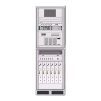
ZTE CDMA Outdoor Basestation-8900 Hardware Manual (155 pages)
CDMA Outdoor Basestation-8900
Brand:
ZTE
| Category:
Portable Generator
| Size: 2 MB
Table of Contents
Table of Contents
3
Preface
7
Cabinet
9
Cabinet Technique Feature
9
Baseband Power Cabinet Outer Structure
9
Baseband Power Cabinet Inner Structure
10
Figure 1 Baseband Power Cabinet Outer Structure
10
Table 1 Baseband Power Cabinet Outer Components
10
Figure 2 Baseband Power Cabinet Inner Structure
11
Heat Exchanger
11
Table 2 Baseband Power Cabinet Inner Structure Description
11
Baseband Subrack
12
Figure 3 Heat Exchanger Structure
12
Transmission Equipment (Optional)
12
Description
13
Figure 4 Baseband Subrack
13
Table 3 Baseband Subrack Modules Description
13
Cable Tray
14
Figure 5 Cable Tray Structure
14
Figure 6 Lightning Subrack Panel
14
Lightning Subrack
14
Figure 7 Power Supply Subrack Structure
15
Power Supply Subrack
15
Table 4 Power Supply Subrack Composition Unit Description
15
Smog Sensor
16
RF Cabinet Outer Structure
16
Figure 8 Smog Sensor Structure
16
RF Cabinet Inner Structure
17
Figure 9 RF Cabinet Outer Structure
17
Table 5 RF Cabinet Outer Components Description
17
Figure 10 RF Cabinet Inner Structure
18
Figure 11 RF Subrack
19
RF Subrack
19
Table 6 RF Cabinet Inner Configuration Description
19
Figure 12 Lightning Filter Structure
20
Lightning Filter (Optional)
20
Table 7 RF Subrack Module Description
20
Storage Battery Cabinet
21
Figure 13 Storage Battery Cabinet Outer Structure
21
Table 8 Storage Battery Cabinet Outer Structure Components
21
Figure 14 Storage Battery Cabinet Inner Structure
22
Modules
23
BBU Modules
23
Control and Clock Module (CC)
23
Figure 15 CC Module Principle
24
Figure 16 CC Module Panel (with Handle)
24
Figure 17 CC Module Panel (Without Handle)
24
Table 10 CC Module Panel Indicator Description
25
Channel Processing Module (CH)
27
Table 11 CC Module Panel Button Description
27
Table 12 CC Module Panel Interface Description
27
Figure 18 CHV Module Principle
28
Figure 19 CHD Module Principle
28
Figure 20 CHV Module Panel
29
Figure 21 CHD Module Panel
29
Table 13 CH Module Panel Indicator Description
29
Fabric Switch Module (FS)
31
Table 14 CH Button Description
31
Figure 22 FS Module Principle
32
Figure 23 FS Module Panel with Handle
32
Figure 24 FS Module Panel Without Handle
32
Table 15 FS Panel Indicator Description
32
Site Alarm Module (SA)
36
Figure 25 SA Module Principle
36
Figure 26 SA Module Panel
37
Table 16 SA Panel Indicator Description
37
Table 17 SA Button Description
37
Table 18 SA Panel Interface Description
37
Fan Array Module (FA)
38
Figure 27 FA Module Principle
38
Power Module (PM)
39
Figure 28 FA Module Panel
39
Table 19 FA Panel Indicator Description
39
Figure 29 PM Module Principle
40
Figure 30 PM Module Panel
41
Table 20 PM Panel Indicator Description
41
Table 21 PM Panel Interface Description
41
RRU Modules
42
Fan Subrack
42
Power Distribution Subrack
42
Figure 31 Fan Subrack Structure
42
Radio System Unit (RSU)
43
Figure 32 Power Distribution Subrack Structure
43
Figure 33 RSU Schematic Diagram
43
Figure 34 RSU Panel
44
Table 22 RSU Panel Indicator Description
44
Table 23 RSU Panel Button Description
45
Table 24 RSU Panel Interface Description
46
Power Distribution Module (PDM)
47
Figure 35 PDM Front Panel
47
Table 25 PDM Front Panel Description
47
Fan Control Module (FCE)
48
Figure 36 PDM Rear Panel
48
Figure 37 FCE Front Panel
48
Table 26 FCE Front Panel Description
48
External Cables
51
External Cable Layout
51
Baseband Power Cabinet Input Power Cable
52
Figure 38 RF Cabinet External Cable Layout
52
Baseband Power Cabinet Grounding Cable
53
Figure 39 Grounding Cable Appearance
53
Table 28 Technical Indices of Baseband Power Cabinet Input
53
Baseband Cabinet and Storage Battery Connecting
54
Cable
54
Baseband Subrack DC Input Power Cable
54
Baseband Cabinet and Storage Battery Connecting Cable
54
Serial Port Monitoring Cable from Power Subrack to Baseband Subrack
55
Figure 42 Serial Port Monitoring Cable between Power
55
Table 29 Power Cable Connection
55
Baseband Subrack and RF Cabinet Connecting Fiber
56
Figure 43 Single-Mode Fiber Appearance
56
Table 30 Serial Port Monitoring Cable Pin Description
56
External Dry Contact of Baseband Subrack
57
Figure 44 Dry Contact Input/Output Cable Appearance
57
Table 31 Dry Contact Input Cable Pin Description
57
Table 32 Dry Contact Output Cable Pin Description
60
Baseband Subrack and Lightning Subrack Connecting Cable
61
Cable
61
Figure 45 Baseband Subrack and Lightning Subrack
61
Baseband Subrack Ethernet Cable
62
Figure 46 Ethernet Cable Appearance
62
Table 34 Ethernet Cable Pin Description
62
GPS Arrester and CC Module Connecting RF Cable
63
Storage Battery Door Control Cable
63
Figure 47 GPS Jumper Appearance
63
Figure 48 Storage Battery Door Control Cable Appearance
63
Storage Battery Temperature Monitoring Cable
64
Storage Battery Water Monitoring Cable
64
E1/T1 Cable on Lightning Subrack LPU
64
Figure 49 Temperature Monitoring Cable Appearance
64
Figure 50 Storage Battery Water Monitoring Cable
64
Figure 51 8-Channel E1/T1 Cable
65
Figure 52 4-Channel E1/T1 Cable
65
Table 35 Description of E1/T1 Cable Pins on Lightning
65
RF Cabinet DC Input Power Cable
67
Table 36 RF Cabinet DC Input Power Cable Technical Indices
67
GPS Antenna Feeder System
69
GPS Antenna Feeder System Structure
69
GPS Antenna
70
Figure 53 GPS Antenna Feeder System Structure
70
Table 37 GPS Antenna Technical Indices
70
GPS Feeder
71
Figure 54 GPS Feeder Structure
71
Table 38 GPS Feeder Cable Technical Indices
71
GPS Arrester
72
Figure 55 One-In-One GPS Arrester Structure
72
Figure 56 Two-In-One GPS Arrester Structure
72
Table 39 One-In-One GPS Arrester Technical Indices
72
GPS Feeder Connector
73
Figure 57 GPS Feeder Connector Structure
73
Table 40 Two-In-One GPS Arrester Technical Indices
73
GPS Grounding Kit
74
Table 41 GPS Feeder Connector Technical Indices
74
Figure 58 GPS Grounding Kit Structure
75
Table 42 GPS Feeder Grounding Kit Technical Indexes
75
Main Antenna Feeder System
77
Main Antenna Feeder System Structure
77
Antenna
83
Feeder Structure
83
Outdoor BBU+RSU Cabinet
85
Cabinet
85
Outdoor BBU+RSU Cabinet Technique Feature
85
Cabinet Outer Structure
85
Figure 64 Cabinet Appearance
86
Cabinet Inner Structure
87
Figure 65 Cabinet Outer Structure
87
Figure 66 Cabinet Inner Structure
88
Outdoor BBU Cabinet
88
Figure 67 Outdoor BBU Cabinet Structure
89
Outdoor RSU Cabinet
89
Fan Box
90
Figure 68 Outdoor RSU Cabinet Structure
90
Figure 69 Fan Box Structure
91
Figure 70 Heater Structure
91
Heat Exchanger
91
Heater
91
Modules
92
Control and Clock Module (CC)
92
Figure 71 Heat Exchanger Position
92
Figure 72 CC Module Principle
93
Figure 73 CC Module Panel (with Handle)
93
Figure 74 CC Module Panel (Without Handle)
93
Table 43 CC Module Panel Indicator Description
94
Channel Processing Module (CH)
96
Table 44 CC Module Panel Button Description
96
Table 45 CC Module Panel Interface Description
96
Figure 75 CHV Module Principle
97
Figure 76 CHD Module Principle
98
Figure 77 CHV Module Panel
98
Figure 78 CHD Module Panel
98
Table 46 CH Module Panel Indicator Description
99
Fabric Switch Module (FS)
100
Table 47 CH Button Description
100
Figure 79 FS Module Principle
101
Figure 80 FS Module Panel with Handle
101
Figure 81 FS Module Panel Without Handle
101
Table 48 FS Panel Indicator Description
102
Site Alarm Module (SA)
105
Figure 82 SA Module Block Diagram
105
Figure 83 SA Module Panel
106
Table 49 SA Panel Indicator Description
106
Table 50 SA Button Description
106
Figure 84 ZXSDR BS8800 Jumpers Location
107
Table 51 SA Panel Interface Description
107
Table 52 ZXSDR BS8800 Jumpers Setting
107
Fan Array Module (FA)
110
Figure 85 FA Module Principle
110
Power Module (PM)
111
Figure 86 FA Module Panel
111
Table 53 FA Panel Indicator Description
111
Figure 87 PM Module Principle
112
Figure 88 PM Module Panel
113
Table 54 PM Panel Indicator Description
113
Table 55 PM Panel Interface Description
113
Fan Control Module (FCE)
114
Figure 89 FCE Module Principle
114
Lpu
115
Figure 90 LPU Panel
115
Table 56 LPU External Interface Description
115
Psu
116
Figure 91 PSU Module Front Panel
116
Apm
117
Figure 92 PSU + APM Subrack Front Panel
117
Table 57 PSU Module Panel Indicator Description
117
Table 58 PSU Panel Button Description
117
Table 59 PSU Panel Interface Description
117
Dpm
118
Figure 93 APM Module Principle
118
Figure 94 APM Module Front Panel
118
Figure 95 DPM Module Principle
119
Figure 96 DPM Front Panel (with Cover)
119
Figure 97 DPM Front Panel (Without Cover)
119
Channel Process Module with Optical Interface
120
CVI
120
Figure 98 CVI-F Principle
121
Figure 99 CVI-C Principle
121
Figure 100 CVI Panel
121
Figure 101 CVI Panel Without Handle
122
Table 60 CVI Panel Indicator Description
122
External Cables
124
External Cable Layout
124
Table 61 CVI Panel Button Description
124
Figure 102 External RF Cable Layout
125
Figure 103 Power and Grounding Cable Layout
126
Figure 104 Data Cable Layout
127
DC Power Cable between PSU and BBU/FCE
128
(Pwr-91238-001)
128
Equipment AC Input Power Cable
128
Figure 105 DC Power Cable (PWR-91238-001) Appearance
128
Figure 106 Equipment AC Input Power Cable Appearance
129
Figure 107 AC Wiring Terminal Structure
129
Grounding Cable
130
Data Cable
130
Figure 108 Grounding Cable Structure
130
Figure 109 Data Cable (DS-91238-001)Structure
130
75-Ohm E1 Cable
135
Figure 110 75-Ohm E1 Cable Appearance (8E1)
135
Figure 111 75-Ohm E1 Cable Appearance (4E1)
135
120-Ohm E1 Cable
137
Figure 112 120-Ohm E1 Cable Appearance (8E1)
138
Figure 113 120-Ohm E1 Cable Appearance (4E1)
138
100-Ohm T1 Cable
141
Figure 114 100-Ohm T1 Cable Appearance
141
RSU DC Input Power Cable
142
High-Speed Cable Connecting BBU and RSU
143
Figure 116 BBU-RSU High-Speed Cable Appearance
143
GPS Jumper
144
RF Jumper
144
Figure 117 GPS Jumper Appearance
144
Figure 118 Cabinet RF Jumper Appearance
144
Figure 119 Antenna Jumper Appearance
145
Figures
147
Tables
151
List of Glossary
155
Advertisement
Advertisement
Related Products
ZTE ZXSDR BS8900
ZTE Baker
ZTE Blade Ii
Zte BOOST B795
Zte Blade Q Plus
Zte B760E
Zte BLADE 521
ZTE ZXSDR BS8908 G060
Zte BladeA3 2020
Zte Blade V40 Vita
Zte Categories
Cell Phone
Modem
Wireless Router
Network Router
Switch
More Zte Manuals
Login
Sign In
OR
Sign in with Facebook
Sign in with Google
Upload manual
Upload from disk
Upload from URL