Table of Contents
Advertisement
Advertisement
Table of Contents

Summary of Contents for Zte ZXSDR BS8900
- Page 1 ZXSDR BS8900 CDMA Outdoor Basestation-8900 Hardware Manual ZTE CORPORATION ZTE Plaza, Keji Road South, Hi-Tech Industrial Park, Nanshan District, Shenzhen, P. R. China 518057 Tel: (86) 755 26771900 Fax: (86) 755 26770801 URL: http://ensupport.zte.com.cn E-mail: support@zte.com.cn...
- Page 2 The contents of this document are protected by copyright laws and international treaties. Any reproduction or distribution of this document or any portion of this document, in any form by any means, without the prior written consent of ZTE CORPO- RATION is prohibited.
-
Page 3: Table Of Contents
Contents Preface ............... i Cabinet.............. 1 Cabinet Technique Feature ..........1 Baseband Power Cabinet Outer Structure......1 Baseband Power Cabinet Inner Structure ......2 Heat Exchanger............3 Transmission Equipment (Optional) ....... 4 Baseband Subrack ............4 Cable Tray ..............6 Lightning Subrack............ - Page 4 External Cables ..........43 External Cable Layout ............43 Baseband Power Cabinet Input Power Cable ......44 Baseband Power Cabinet Grounding Cable ......45 Baseband Cabinet and Storage Battery Connecting Cable ..............46 Baseband Subrack DC Input Power Cable......46 Serial Port Monitoring Cable from Power Subrack to Baseband Subrack ..........47 Baseband Subrack and RF Cabinet Connecting Fiber ...48 External Dry Contact of Baseband Subrack......49...
- Page 5 Heat Exchanger ..........83 Modules ...............84 Control and Clock Module (CC) ........84 Channel Processing Module (CH)........88 Fabric Switch Module (FS)...........92 Site Alarm Module (SA) ..........97 Fan Array Module (FA) ..........102 Power Module (PM) ..........103 Fan Control Module (FCE) ......... 106 LPU ...............
-
Page 7: Preface
Preface Confidential and Proprietary Information of ZTE CORPORATION... - Page 8 ZXSDR BS8900 Hardware Manual This page is intentionally blank. Confidential and Proprietary Information of ZTE CORPORATION...
-
Page 9: Cabinet
RF Cabinet Inner Structure ..........9 Storage Battery Cabinet .............13 Cabinet Technique Feature ZXSDR BS8900 is featured by the following items: 1. The cabinet is painted in light grey, pleasant to eyes. 2. The cabinet design is technique oriented with reasonable layout and color arrangement. -
Page 10: Baseband Power Cabinet Inner Structure
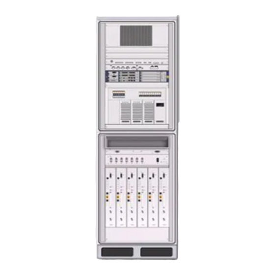
Prevents the equipments from sunshine. Handle Used to open and close the cabinet door. Equipped with alarm lock. Vent Helps cabinet heat-dissipation. Baseband Power Cabinet Inner Structure Figure 2 shows the baseband power cabinet inner structure. Confidential and Proprietary Information of ZTE CORPORATION... -
Page 11: Heat Exchanger
Judging from the feedback indices from temperature sensor, the heat exchanger provides cooling or heating function to keep a sta- ble temperature inside the cabinet and ensure the normal opera- tion of equipments. Confidential and Proprietary Information of ZTE CORPORATION... -
Page 12: Transmission Equipment (Optional)
The transmission equipment adopts - 48 V DC supply with 200 W power consumption. The transmission equipment completes transmission signals con- version. ZXSDR BS8900 supports various types of transmis- sion equipments, such as SDH, microwave, PDH optical transmis- sion and HDSL. -
Page 13: Figure 4 Baseband Subrack
Network Switch 1 module is configured Module as default. Supports load sharing. Not support active/standby mode. Power Module 1 module is configured as default. 2 are configured upon specific request. Confidential and Proprietary Information of ZTE CORPORATION... -
Page 14: Cable Tray
ABLE TRUCTURE Lightning Subrack The lightning subrack prevents the external RS232/RS485, dry contact, E1/T1 and FE/GE interfaces of ZXSDR BS8900 out- door transmission equipment from lightning and avoids damages to the equipment caused by lightning induction and static electric- ity. -
Page 15: Power Supply Subrack
OWER UPPLY UBRACK OMPOSITION ESCRIPTION Unit Quantity Description AC distribution Provides 2 sets of standby outputs in unit standard configuration. DC distribution Provides overload protection for DC unit output branch and battery branch. Confidential and Proprietary Information of ZTE CORPORATION... -
Page 16: Smog Sensor
RF cabinet outer structure consists of the cabinet proper, cabinet door, sun shield and the base, as is shown in Figure The cabinet dimension is 850 mm × 600 mm × 600 mm (height × width × depth). Confidential and Proprietary Information of ZTE CORPORATION... -
Page 17: Rf Cabinet Inner Structure
Used to open and close the cabinet door. Handle Equipped with alarm lock against theft. Rear cover plate Able to be disassembled and convenient for cable connection. RF Cabinet Inner Structure Figure 10 shows the RF cabinet inner structure. Confidential and Proprietary Information of ZTE CORPORATION... -
Page 18: Figure 10 Rf Cabinet Inner Structure
ZXSDR BS8900 Hardware Manual 10 RF C IGURE ABINET NNER TRUCTURE Fan subrack Power distribution subrack RF subrack Base Reserved for lightning filter Air intake vent Sun shield Confidential and Proprietary Information of ZTE CORPORATION... -
Page 19: Rf Subrack
If installed in heap with other cabinet, it needs sun shield for upper layer and base for lower layer. RF Subrack Figure 11 illustrates the ZXSDR BS8900 RF subrack. 11 RF S IGURE UBRACK Confidential and Proprietary Information of ZTE CORPORATION... -
Page 20: Lightning Filter (Optional)
RF cabinet in heap. 2. Lightning filter is unnecessary when one RF cabinet is installed with a baseband power cabinet in heap. Confidential and Proprietary Information of ZTE CORPORATION... -
Page 21: Storage Battery Cabinet
Used to open and close cabinet door. Equipped Handle with alarm lock. Vent helps cabinet heat-dissipation. Base Used to fix the cabinet with alarm system against theft. Figure 14 shows the storage battery cabinet inner structure. Inner Structure Confidential and Proprietary Information of ZTE CORPORATION... -
Page 22: Figure 14 Storage Battery Cabinet Inner Structure
1~2 sets, configured according to Battery Set actual conditions. A single cabinet supports a maximum capacity of 300 Ah with each set of 150 Ah. Extra storage battery cabinet is needed for more demands. Confidential and Proprietary Information of ZTE CORPORATION... -
Page 23: Modules
Principle ply unit, storage unit, Abis interface unit, FI unit, MV unit, Ethernet exchange unit, FPGA logic unit and EPLD logic unit. Figure 15 illustrates the principle of the CC module. Confidential and Proprietary Information of ZTE CORPORATION... -
Page 24: Figure 15 Cc Module Principle
ANDLE Note: Some buttons will be covered if the CC module panel is equipped with handle, as illustrated in Figure 16 Figure Table 10 describes the indicators on the CC module panel. Indicator Confidential and Proprietary Information of ZTE CORPORATION... -
Page 25: Table 10 Cc Module Panel Indicator Description
0.3 seconds and off for 0.3 seconds when the antenna feeder is normal but can not search the satellite. Slower flash: On for 2.5 seconds and off for 2.5 seconds when the antenna is short—circuited. Confidential and Proprietary Information of ZTE CORPORATION... - Page 26 1 second and off for 1 second when the board is in active/standby changeover. Fast flash: On for 70 ms and off for 70 ms when communication between CC board and OMP Confidential and Proprietary Information of ZTE CORPORATION...
-
Page 27: Channel Processing Module (Ch)
The forward modulation and reverse demodulation of base- band CDMA key technologies, such as diversity technique, RAKE receiving, softer-handoff and power control Mixed insertion of CHV and CHD modules to support 1x and EV-DO service. Confidential and Proprietary Information of ZTE CORPORATION... -
Page 28: Figure 18 Chv Module Principle
MPC unit. Figure 19 shows the principle of CHD module. 19 CHD M IGURE ODULE RINCIPLE The dimensions of CH module in mm are: 148.8 (H) x 19.0 (W) x Measurement 181.5 (D). Confidential and Proprietary Information of ZTE CORPORATION... -
Page 29: Figure 20 Chv Module Panel
On and 0.125s the forward baseband The first sec- signal failure ond: one flash while FS0/FS1 means com- board munication connects to with FS0 is CH board. normal and Off means communica- Confidential and Proprietary Information of ZTE CORPORATION... - Page 30 Green Communica- Controlled by On: normal tion status CPU, EPLD communica- indicator be- transparent tion between tween CPU transmission CPU and MMC and MMC mode Off: failed communica- tion between CPU and MMC. Confidential and Proprietary Information of ZTE CORPORATION...
-
Page 31: Fabric Switch Module (Fs)
The FS module comprises active/standby control unit, MCU0 unit, Principle MCU1 unit, EPLD logic, optical interface control unit, FPGA unit, optical receiving and transmitting circuit and clock processing cir- cuit, as shown in Figure Confidential and Proprietary Information of ZTE CORPORATION... -
Page 32: Figure 22 Fs Module Principle
At most four baseband by FPGA; flashes per link running the flash second. On status frequency for 0.125 indicator is 8Hz; seconds and it means off for 0.125 the locking seconds. status of The first Confidential and Proprietary Information of ZTE CORPORATION... - Page 33 4th is unavailable. sixteenth second: Six flashes mean the 5th link is normal. Off when the 5th is broken. Recycle again per 18 seconds. Off when an error occurs on the 61.44M clock. Confidential and Proprietary Information of ZTE CORPORATION...
- Page 34 Five flashes means the 4th link is normal. Off when the link is broken. Recycle again per 15 seconds. Off when an error occurs on the 61.44M clock. Confidential and Proprietary Information of ZTE CORPORATION...
- Page 35 Off when the module is abnormal. Alarm MMC control On when Indicator indicator an alarm occurs on the module. Off when no alarm occurs on the module. Confidential and Proprietary Information of ZTE CORPORATION...
-
Page 36: Site Alarm Module (Sa)
The dimensions of SA module in mm are: 73.8 (H) x 19.0 (W) x Measurement 181.5 (D). The dimensions of SA module in inches are: 2 14/16 (H) x 12/16 (W) x 7 12/16 (D). Figure 26 shows the panel of SA module. Panel Confidential and Proprietary Information of ZTE CORPORATION... -
Page 37: Figure 26 Sa Module Panel
Reset button Table 18 describes the panel interfaces on SA module. Panel Interface 18 SA P ABLE ANEL NTERFACE ESCRIPTION Description Interface Name Mon/Abis Abis connection ,RS232 / RS485 monitoring and dry contact monitoring Confidential and Proprietary Information of ZTE CORPORATION... -
Page 38: Fan Array Module (Fa)
LED drive, power supply, fan, backplane interface and FL unit. Fig- ure 27 shows the principle of the FA module. 27 FA M IGURE ODULE RINCIPLE Figure 28 shows the panel of the FA module. Panel Confidential and Proprietary Information of ZTE CORPORATION... -
Page 39: Power Module (Pm)
FA is powered off (i.e., the RUN indicator is off). Power Module (PM) module performs the following functions: Function 16 internal interfaces for +12 V load power 16 internal interfaces for +3.3 V management power Confidential and Proprietary Information of ZTE CORPORATION... -
Page 40: Figure 29 Pm Module Principle
The dimensions of PM module in mm are: 73.8 (H) x 29.0 ( W) x Measurement 181.5 (D) The dimensions of PM module in inches are: 2 14/16 (H) x 1 2/16 ( W) x 7 12/16 (D) Figure 30 shows the panel of PM module. Panel Confidential and Proprietary Information of ZTE CORPORATION... -
Page 41: Figure 30 Pm Module Panel
Table 21 describes the panel interfaces of PM module. Panel Interface 21 PM P ABLE ANEL NTERFACE ESCRIPTION Interface Description RS232 debugging interface -48V/-48V RTN -48V DC input interface Confidential and Proprietary Information of ZTE CORPORATION... -
Page 42: Rru Modules
2 bus bar jackets, spacer and the shell with the break- ers controlling over the power distribution to 6 RSUs and the fan subrack. Figure 32 shows the structure of the power distribution subrack. Confidential and Proprietary Information of ZTE CORPORATION... -
Page 43: Radio System Unit (Rsu)
The RSU module comprises transceiver board (RTR), power am- Principle plifier (PA), duplexer (DFL), lightning interface board (PIBC) and power unit (RPDC). Figure 33 illustrates the RSU’s schematic dia- gram. 33 RSU S IGURE CHEMATIC IAGRAM Confidential and Proprietary Information of ZTE CORPORATION... -
Page 44: Figure 34 Rsu Panel
RSU running On when RSU is indicator being reset or started. Blinks in 1Hz when RSU runs normally. Blinks in 5 Hz when the version is being downloaded. Off when Self test fails. Confidential and Proprietary Information of ZTE CORPORATION... -
Page 45: Table 23 Rsu Panel Button Description
There is only one button (RST) on the RSU panel. Table 23 Button scribes the button. 23 RSU P ABLE ANEL UTTON ESCRIPTION Button Description Reset button Table 24 describes RSU panel interfaces. Panel Interfaces Confidential and Proprietary Information of ZTE CORPORATION... -
Page 46: Table 24 Rsu Panel Interface Description
PC and test Debug interface device (test and test board) interface TEST Testing device Tx Test signal interface Peripheral Provides input interface for four channels of dry contact signals and RS 485 environment monitoring interface Confidential and Proprietary Information of ZTE CORPORATION... -
Page 47: Power Distribution Module (Pdm)
Fan subrack power ON: Powered on OFF: Powered off supply Power supply of RF ON: Powered on unit 1 OFF: Powered off Power supply of RF ON: Powered on unit 2 OFF: Powered off Confidential and Proprietary Information of ZTE CORPORATION... -
Page 48: Fan Control Module (Fce)
It is connected to the fan power supply of interface the power distribution subrack. Power That it turns green indicates the fan unit indicator is powered on. Reset button Resets the whole fan system. Confidential and Proprietary Information of ZTE CORPORATION... - Page 49 Chapter 2 Modules Silk Print Name Description Alarm That it turns red indicates there is an indicator alarm occurring. Run indicator That it flashes indicates the fan system runs normally. Monitoring Monitors fans. interface Confidential and Proprietary Information of ZTE CORPORATION...
- Page 50 ZXSDR BS8900 Hardware Manual This page is intentionally blank. Confidential and Proprietary Information of ZTE CORPORATION...
-
Page 51: External Cables
E1/T1 Cable on Lightning Subrack LPU .........56 RF Cabinet DC Input Power Cable ........59 External Cable Layout External cables of ZXSDR BS8900 RF cabinet include power cable, RF cable, fiber and grounding cable. Figure 38 shows the cable layout. Confidential and Proprietary Information of ZTE CORPORATION... -
Page 52: Baseband Power Cabinet Input Power Cable
AC phase line L with Brown AC power Base- the maximum current band distri- of 60A bution power equip- cabinet ment power AC zero line N with Black shielding the maximum current of 60A Confidential and Proprietary Information of ZTE CORPORATION... -
Page 53: Baseband Power Cabinet Grounding Cable
The grounding cable is a 35 mm yellow and green copper wire. Figure 39 shows the appearance of the grounding cable. 39 G IGURE ROUNDING ABLE PPEARANCE Confidential and Proprietary Information of ZTE CORPORATION... -
Page 54: Baseband Cabinet And Storage Battery Connecting
B connected to the power output terminal in the baseband power cabinet. Baseband Subrack DC Input Power Cable The ZXSDR BS8900 baseband subrack supports –48V DC power supply only. Figure 41 shows the appearance of the baseband subrack DC input power cable. -
Page 55: Serial Port Monitoring Cable From Power Subrack To Baseband Subrack
42 S IGURE ERIAL ONITORING ABLE ETWEEN OWER UBRACK AND ASEBAND UBRACK Table 30 describes serial port monitoring cable pins. Confidential and Proprietary Information of ZTE CORPORATION... -
Page 56: Baseband Subrack And Rf Cabinet Connecting Fiber
This cable cannot provide RS232 interface and RS485 interface simultaneously. Baseband Subrack and RF Cabinet Connecting Fiber The fiber implements signal exchange between ZXSDR BS8900 baseband subrack and RF cabinet. The fiber used by ZXSDR BS8900 is a single-mode fiber with LC/LC connectors at both ends. -
Page 57: External Dry Contact Of Baseband Subrack
External Dry Contact of Baseband Subrack The dry contact input/output cable connects the ZXSDR BS8900 to external environment monitoring system to receive dry contact signals from external equipment and transmit dry contact signals of the ZXSDR BS8900 . - Page 58 Dry contact input for switch signals DRY_IN6– Dry contact input for switch signals DRY_IN7+ Dry contact input for switch signals DRY_IN7– Dry contact input for switch signals DRY_IN8+ Dry contact input for switch signals Confidential and Proprietary Information of ZTE CORPORATION...
- Page 59 Dry contact input for switch signals DRY_IN12– Dry contact input for switch signals DRY_IN13+ Dry contact input for switch signals DRY_IN13– Dry contact input for switch signals DRY_IN14+ Dry contact input for switch signals Confidential and Proprietary Information of ZTE CORPORATION...
-
Page 60: Table 32 Dry Contact Output Cable Pin Description
Dry contact output for switch signals Dry contact DRY_OUT1– output for switch signals DRY_OUT2+ Dry contact output for switch signals DRY_OUT2– Dry contact output for switch signals DRY_OUT3+ Dry contact output for switch signals Confidential and Proprietary Information of ZTE CORPORATION... -
Page 61: Cable
Both ends A and B of this cable are SCSI connectors. Figure 45 shows its appearance. 45 B IGURE ASEBAND UBRACK IGHTNING UBRACK ONNECTING ABLE PPEARANCE Table 33 describes the cable connection relationship between base- band subrack and lightning subrack. Confidential and Proprietary Information of ZTE CORPORATION... -
Page 62: Baseband Subrack Ethernet Cable
Table 34 describes Ethernet cable pins. ABLE THERNET ABLE ESCRIPTION Name Description Pin at Pin at quenc End A End B Abis/Iub_ETH_TX+ Transmits signals Abis/Iub_ETH_TX- Transmits signals Abis/Iub_ETH_RX+ Receives signals Abis/Iub_ETH_RX- Receives signals Confidential and Proprietary Information of ZTE CORPORATION... -
Page 63: Gps Arrester And Cc Module Connecting Rf Cable
Cable The GPS jumper connects GPS arrester to CC module and provides GPS clock input signals for CC to convert these signals into various clock signals for ZXSDR BS8900 to use. Figure 47 shows the appearance of the GPS jumper. -
Page 64: Storage Battery Temperature Monitoring Cable
E1/T1 Cable on Lightning Subrack LPU The E1/T1 cable on lightning subrack LPU transmits E1/T1 signals between Abis interfaces or cascaded BTSs and is classified into 4–channel E1/T1 cable and 8–channel E1/T1 cable. Confidential and Proprietary Information of ZTE CORPORATION... -
Page 65: Figure 51 8-Channel E1/T1 Cable
Receives signal E1_RX1- negative (micro-coax 1-1-outer 2 shielding ground) Transmits signal E1_TX2+ positive (micro-coax 1-4-inner 3 signal) Transmits signal 1-4-outer E1_TX2- negative (micro-coax 3 shielding ground) Transmits signal E1_RX2+ positive (micro-coax 1-3-inner 4 signal) Confidential and Proprietary Information of ZTE CORPORATION... - Page 66 Receives signal E1_RX5+ positive (micro-coax 2-1-inner 2 signal) Receives signal E1_RX5- 2-1-outer negative (micro-coax 2 shielding ground) Transmits signal E1_TX6+ positive (micro-coax 2-4-inner 3 signal) Transmits signal E1_TX6- negative (micro-coax 2-4-outer 3 shielding ground) Confidential and Proprietary Information of ZTE CORPORATION...
-
Page 67: Rf Cabinet Dc Input Power Cable
RVYZ3×10mm //ZA-RVY3*10 type. Table 36 describes technical indices of the cable. 36 RF C DC I ABLE ABINET NPUT OWER ABLE ECHNICAL NDICES Name Index Insulator layer 1.0 mm/4.9 mm2 thickness/outer di- ameter Confidential and Proprietary Information of ZTE CORPORATION... - Page 68 Blue: -48V; Brown: -48 V GND; Yellow color and green: PE ≤1.83 /km Conduct resistance Allowed tempera- -40 75 ture range Fire resistance ca- Meet UL1581 pability and Day- light resistance ca- pability Confidential and Proprietary Information of ZTE CORPORATION...
-
Page 69: Gps Antenna Feeder System
GPS antenna feeder system receives navigation and location sig- nals from GPS satellites and demodulates these signals into fre- quency and clock signals for relevant units of the ZXSDR BS8900 Figure 53 shows the structure of the ZXSDR BS8900 GPS antenna feeder system. -
Page 70: Gps Antenna
Gain plifier’s gain). Polarization right hand circular polarization Impedance 50 Ω Interface Noise coefficient <1.5 dB Power supply voltage 5 V DC~12 V DC power supply current <35 mA Working temperature Storage temperature Confidential and Proprietary Information of ZTE CORPORATION... -
Page 71: Gps Feeder
Name 1/4″ foam polyethylene insulation wrinkle copper tube external conductor RF coaxial cable. Characteristic impedance 50 Ω Inner conductor calibra- 2.6 mm. tion outer diameter Insulation layer calibra- 6 mm. tion outer diameter Confidential and Proprietary Information of ZTE CORPORATION... -
Page 72: Gps Arrester
TRUCTURE 56 T GPS A IGURE RRESTER TRUCTURE Table 39 lists the technical indices of one-in-one GPS arrester. Technical Indices 39 O GPS A ABLE RRESTER ECHNICAL NDICES Index Specification Impedance 50 Ω Confidential and Proprietary Information of ZTE CORPORATION... -
Page 73: Gps Feeder Connector
GPS feeder connector’s impedance is 50 ohm. Figure 57 shows the GPS feeder connector structure. Structure 57 GPS F IGURE EEDER ONNECTOR TRUCTURE Table 41 lists the technical indices of GPS feeder connector. Technical Indices Confidential and Proprietary Information of ZTE CORPORATION... -
Page 74: Gps Grounding Kit
No acid or alkaline gas GPS Grounding Kit When the GPS feeder uses 1/4" RF coaxial cable, the GPS feeder Structure grounding kit should be glue free. Structure of GPS grounding kit is shown in Figure Confidential and Proprietary Information of ZTE CORPORATION... -
Page 75: Figure 58 Gps Grounding Kit Structure
ROUNDING ECHNICAL NDEXES Technical Parameter Specification Material of grounding kit stainless steel Material of copper braid belt purple copper Grounding cable copper core cross-sec- 10 mm tional area 800 mm. Grounding cable length Confidential and Proprietary Information of ZTE CORPORATION... - Page 76 ZXSDR BS8900 Hardware Manual This page is intentionally blank. Confidential and Proprietary Information of ZTE CORPORATION...
-
Page 77: Main Antenna Feeder System
In this configuration, generally ZXSDR BS8900 installation position is near antenna and they are all installed on the build- ZXSDR ing top. ZXSDR BS8900 is connected to the antenna by BS8900 1/2″feeder directly, occasionally 5/4″or 7/8″feeder is adopted, as configuration with... - Page 78 ZXSDR BS8900 Hardware Manual 59 ZXSDR BS8900 C IGURE ONFIGURED WITH OMMON NTENNA In this configuration, generally ZXSDR BS8900 is installed on ZXSDR BS8900 the tower. ZXSDR BS8900 is connected to the antenna by configuration with 5/4″or 7/8″feeder, as shown in...
- Page 79 Chapter 5 Main Antenna Feeder System AISG dual power 60 ZXSDR BS8900 C IGURE ONFIGURATION WITH OMMON amplifier , AISG D NTENNA OWER MPLIFIER Confidential and Proprietary Information of ZTE CORPORATION...
- Page 80 ZXSDR BS8900 Hardware Manual In this configuration, generally ZXSDR BS8900 installed near the ZXSDR BS8900 antenna on the building top. ZXSDR BS8900 is con- nected to configuration the antenna by 1/2″feeder directly, occasionally 5/4″or with electronic 7/8″feeder is adopted, as shown in...
- Page 81 Chapter 5 Main Antenna Feeder System adjustment antenna (2) 62 ZXSDR BS8900 C IGURE ONFIGURATION WITH LECTRONIC DJUSTMENT NTENNA Confidential and Proprietary Information of ZTE CORPORATION...
- Page 82 ZXSDR BS8900 Hardware Manual In this configuration, generally ZXSDR BS8900 is installed near ZXSDR BS8900 the top of the tower. ZXSDR BS8900 is connected to the configuration antenna by 5/4″or 7/8″feeder is adopted, as shown in Figure with electronic adjustment...
-
Page 83: Antenna
Feeder Structure The feeder is used to receive and transmit radio RF signals between the antenna and the ZXSDR BS8900 . There are many types of feeder cables such as 1/2 inch and 7/8 inch feeder cable. When the distance between the ZXSDR BS8900 cabinet and antenna is less, then 1/2 inch feeder cable is used. - Page 84 ZXSDR BS8900 Hardware Manual This page is intentionally blank. Confidential and Proprietary Information of ZTE CORPORATION...
-
Page 85: Outdoor Bbu+Rsu Cabinet
MTBF is more than 100000hr. The components and parts are made of environmental protection materials without lead and can be recycled. Cabinet Outer Structure Figure 64 shows the appearance of the outdoor BBU+RSU cabinet. Confidential and Proprietary Information of ZTE CORPORATION... -
Page 86: Figure 64 Cabinet Appearance
Outdoor BBU cabinet: 210 mm (W) × 600 mm (H) × 480 mm Outdoor RSU cabinet: 110 mm (W) × 600 mm (H) × 480 mm The cabinet contains an outdoor BBU cabinet and an outdoor RSU cabinet, as shown in Figure Confidential and Proprietary Information of ZTE CORPORATION... -
Page 87: Cabinet Inner Structure
Appendix A Outdoor BBU+RSU Cabinet 65 C IGURE ABINET UTER TRUCTURE Cover Base (optional) Outdoor BBU cabinet Outdoor RSU cabinet Heat exchanger Cabinet Inner Structure Figure 66 shows the inner structure of the outdoor BBU+RSU cab- inet. Confidential and Proprietary Information of ZTE CORPORATION... -
Page 88: Outdoor Bbu Cabinet
Outdoor BBU Cabinet The dimensions of the outdoor BBU cabinet with the heat ex- changer are: 210 mm (W) × 600 mm (H) × 480 mm (D). Figure shows the structure of the cabinet. Confidential and Proprietary Information of ZTE CORPORATION... -
Page 89: Outdoor Rsu Cabinet
The outdoor RSU cabinet and the outdoor BBU cabinet can be in- stalled in the same cabinet or in different cabinets. The dimensions of the outdoor RSU cabinet are: 110 mm (W) × 600 mm (H) × 480 mm (D). Confidential and Proprietary Information of ZTE CORPORATION... -
Page 90: Fan Box
68 O RSU C IGURE UTDOOR ABINET TRUCTURE Fan Box The fan box is installed at the upside inlet to cool the outdoor BBU cabinet. Figure 69 shows the structure of the fan box. Confidential and Proprietary Information of ZTE CORPORATION... -
Page 91: Heater
70 H IGURE EATER TRUCTURE Heat Exchanger The outdoor BBU cabinet is cooled by a heat exchanger that is located at the back of the case for back air exhaust, as shown in Figure Confidential and Proprietary Information of ZTE CORPORATION... -
Page 92: Modules
GE Ethernet exchange function One USB interface Subrack management Baseband modulation and demodulation Provision of external clock extension interface (IEEE1588) and communication extension interface (through the local mainte- nance interface). Confidential and Proprietary Information of ZTE CORPORATION... -
Page 93: Figure 72 Cc Module Principle
CC module panel with han- Panel dle. Figure 17 shows the appearance of the CC module panel with- out handle. 73 CC M IGURE ODULE ANEL WITH ANDLE 74 CC M IGURE ODULE ANEL WITHOUT ANDLE Confidential and Proprietary Information of ZTE CORPORATION... -
Page 94: Table 43 Cc Module Panel Indicator Description
Off when the antenna feeder and the satellite are being initialized. Slow flash: On for 1.5 seconds and off for 1.5 seconds when the antenna feeder is broken Quick flash: On for 0.3 seconds and Confidential and Proprietary Information of ZTE CORPORATION... - Page 95 0.3 seconds when the board is under normal operation. Slow flash: On for 2 seconds and off for 2 seconds when the board is in active/standby pre-changeover. Slow flash: On for 1 second and Confidential and Proprietary Information of ZTE CORPORATION...
-
Page 96: Channel Processing Module (Ch)
Debugging or local maintenance Connecting the external receiver (RS485, PP1S and 2M interfaces) Connecting GPS antenna externally TX/RX Connecting the optical interface between BBU and BSC Channel Processing Module (CH) module performs the following functions: Function Confidential and Proprietary Information of ZTE CORPORATION... -
Page 97: Figure 75 Chv Module Principle
ODULE RINCIPLE CHD module consists of multiplexing and de-multiplexing unit, clock processing unit, ARM unit, DSP unit, modulation and de- modulation unit and MPC unit. Figure 19 shows the principle of CHD module. Confidential and Proprietary Information of ZTE CORPORATION... -
Page 98: Figure 76 Chd Module Principle
CHV module with and without handle respectively. Figure 21 shows the panel appearance of CHD module with and without handle respectively. 77 CHV M IGURE ODULE ANEL 78 CHD M IGURE ODULE ANEL Confidential and Proprietary Information of ZTE CORPORATION... -
Page 99: Table 46 Ch Module Panel Indicator Description
Off. normal. Quick flash: 10ms wrong, 0.125s On and 0.125s Off. Off: 50CHIP wrong. Green Reservation Controlled by CPU, EPLD transparent transmission mode Confidential and Proprietary Information of ZTE CORPORATION... -
Page 100: Fabric Switch Module (Fs)
Supports six remote baseband fiber interfaces. The logic unit implements all the functions except for optical interface processing. The FS module comprises active/standby control unit, MCU0 unit, Principle MCU1 unit, EPLD logic, optical interface control unit, FPGA unit, Confidential and Proprietary Information of ZTE CORPORATION... -
Page 101: Figure 79 Fs Module Principle
Figure 24 show the FS module panel. Panel 80 FS M IGURE ODULE ANEL WITH ANDLE 81 FS M IGURE ODULE ANEL WITHOUT ANDLE Table 15 describes the indicators on FS panel. Indicator Confidential and Proprietary Information of ZTE CORPORATION... -
Page 102: Table 48 Fs Panel Indicator Description
4th link is normal and Off means the 4th is unavailable. sixteenth second: Six flashes mean the 5th link is normal. Off when Confidential and Proprietary Information of ZTE CORPORATION... - Page 103 The tenth second: Four flashes means the 3rd link is normal. Off when the link is broken. thirteenth second: Five flashes means the 4th link is normal. Off when the link is Confidential and Proprietary Information of ZTE CORPORATION...
- Page 104 Blinks in 1 Hz flash when the module runs normally. On when the mod- ule is start- ing the ver- sion after download- ing it suc- cessfully. Off when Confidential and Proprietary Information of ZTE CORPORATION...
-
Page 105: Site Alarm Module (Sa)
SA module consist of management unit, reset unit, monitoring Principle unit, E1/T1 interface protection unit and power unit.Figure 82 lustrates the working block diagram of SA module. 82 SA M IGURE ODULE LOCK IAGRAM Confidential and Proprietary Information of ZTE CORPORATION... -
Page 106: Figure 83 Sa Module Panel
Table 50 describes the button on the panel of SA module. Button 50 SA B ABLE UTTON ESCRIPTION Button Name Description Reset button Table 51 describes the panel interfaces on SA module. Panel Interface Confidential and Proprietary Information of ZTE CORPORATION... -
Page 107: Figure 84 Zxsdr Bs8800 Jumpers Location
Mon/Abis monitoring and dry contact monitoring Jumpers Note: In ZXSDR BS8900 , the jumpers are located on the SA mod- ule. There are 6 sets of jumpers on SA module: X1 ~ X6. Figure Jumpers Location and Structure 84shows the jumpers structure and locations in SA module. - Page 108 ON means cable shield is connected to grounding terminal; OFF means cable shield is hanging (not connected). BSC_RR5, set 5th E1/T1 channel RRING_5 (Recieving). ON means cable shield is connected to grounding terminal; Confidential and Proprietary Information of ZTE CORPORATION...
- Page 109 Sets the BDS rack ID. Supports eight cas- cades of BDS rack at most. BDS_ID Setting BDS_ID<2>, BDS_ID<1> and BDS_ID<0> configuration ranges from “000” to “111” while MBDS is configured as “000” by de- fault. Confidential and Proprietary Information of ZTE CORPORATION...
-
Page 110: Fan Array Module (Fa)
LED drive, power supply, fan, backplane interface and FL unit. Fig- ure 27 shows the principle of the FA module. 85 FA M IGURE ODULE RINCIPLE Figure 28 shows the panel of the FA module. Panel Confidential and Proprietary Information of ZTE CORPORATION... -
Page 111: Power Module (Pm)
FA is powered off (i.e., the RUN indicator is off). Power Module (PM) module performs the following functions: Function 16 internal interfaces for +12 V load power 16 internal interfaces for +3.3 V management power Confidential and Proprietary Information of ZTE CORPORATION... -
Page 112: Figure 87 Pm Module Principle
The dimensions of PM module in mm are: 73.8 (H) x 29.0 ( W) x Measurement 181.5 (D) The dimensions of PM module in inches are: 2 14/16 (H) x 1 2/16 ( W) x 7 12/16 (D) Figure 30 shows the panel of PM module. Panel Confidential and Proprietary Information of ZTE CORPORATION... -
Page 113: Figure 88 Pm Module Panel
Table 21 describes the panel interfaces of PM module. Panel Interface 55 PM P ABLE ANEL NTERFACE ESCRIPTION Description Interface RS232 debugging interface -48V/-48V RTN -48V DC input interface Confidential and Proprietary Information of ZTE CORPORATION... -
Page 114: Fan Control Module (Fce)
The FCE module comprises fan detection control unit, main control Principle unit, BBU interface unit, environment monitoring unit and power interface unit. Figure 89 illustrates the principle of the FCE module. 89 FCE M IGURE ODULE RINCIPLE Confidential and Proprietary Information of ZTE CORPORATION... -
Page 115: Lpu
Appendix A Outdoor BBU+RSU Cabinet The Line Lighting Protection Unit (LPU) protects ZXSDR BS8900 Function external RS232/RS485 interface, contacts, E1/T1 terfaces and FE/GE electrical ports from lightning to prevent the equipment being damaged due to abnormal induction thunder or static electricity. -
Page 116: Psu
The Power System Unit (PSU), with the cooperation of the AC Function Power lightning Module (APM), coverts input AC power into —48V DC power to supply for the ZXSDR BS8900 system, imple- menting lightning protection, filtering, AC primary conversion, dis- tribution and grounding of working power. -
Page 117: Apm
3–core safety AC input socket The AC lightning protection module and the Power System Function Unit (PSU) and power distribution terminals compose the power subsystem, which converts input AC power into —48V DC power to Confidential and Proprietary Information of ZTE CORPORATION... -
Page 118: Dpm
The DC lightning protection module supports -48V DC power Function input and implements lightning protection, filtering, distribution and grounding of working power supply. Figure 95 illustrates the principle of the DPM module. Principle Confidential and Proprietary Information of ZTE CORPORATION... -
Page 119: Figure 95 Dpm Module Principle
Panel 96 DPM F IGURE RONT ANEL WITH OVER 97 DPM F IGURE RONT ANEL WITHOUT OVER —48V OUTPUT1/—48V OUTPUT2 HEATER (power supply interface for heater) LSP (Power arrester) —48V terminal -48VRTN terminal Confidential and Proprietary Information of ZTE CORPORATION... -
Page 120: Channel Process Module With Optical Interface
CSM6700 system, ARM subsystem, clock unit, Ethernet interface and optical transceiver. The CVI module can work in F (CVI-F) mode or C (CVI-C) mode when being loaded different FPGA versions. CVI-F integrates FS and CHV functions. Confidential and Proprietary Information of ZTE CORPORATION... -
Page 121: Figure 98 Cvi-F Principle
99 CVI-C P IGURE RINCIPLE The dimensions of the CVI module are: 148.8mm (H)×19.0mm Dimension (W)×181.5mm (D). Figure 100 Figure 101 shows the panel of the CVI module. Panel 100 CVI P IGURE ANEL Confidential and Proprietary Information of ZTE CORPORATION... -
Page 122: Figure 101 Cvi Panel Without Handle
Green link the reverse link that link 0 is running between optical normal. indicator fiber and FS when the link is reverse optical unavailable. interface. The fourth second: Two flashes indicate that link Confidential and Proprietary Information of ZTE CORPORATION... - Page 123 FS unavailable. forward SERDES. The seventh second: Three flashes indicate that link 2 is normal. when the link is unavailable. The tenth second: Four flashes indicate that link 3 is normal. Off Confidential and Proprietary Information of ZTE CORPORATION...
-
Page 124: External Cables
BBU and RSU, GPS jumper and monitoring cable, which are led in from the bottom of cabinet. Figure 102 illustrates the external RF cable layout of the cabinet. RF Cable Layout Confidential and Proprietary Information of ZTE CORPORATION... -
Page 125: Figure 102 External Rf Cable Layout
Appendix A Outdoor BBU+RSU Cabinet 102 E RF C IGURE XTERNAL ABLE AYOUT GPS jumper Main antenna feeder cable GPS feeder Confidential and Proprietary Information of ZTE CORPORATION... -
Page 126: Figure 103 Power And Grounding Cable Layout
Equipment AC input power cable (protection ground) Equipment AC input power cable FCE DC power cable (live wire) RSU DC power cable Figure 104 illustrates the data cable layout of the cabinet. Data Cable Layout Confidential and Proprietary Information of ZTE CORPORATION... -
Page 127: Figure 104 Data Cable Layout
Appendix A Outdoor BBU+RSU Cabinet 104 D IGURE ABLE AYOUT RS485 monitoring cable to FCE Data cable High-speed cable connecting BBU to RSU RS232/RS485 monitoring cable Dry contact input/output cable Trunk cable Confidential and Proprietary Information of ZTE CORPORATION... -
Page 128: Dc Power Cable Between Psu And Bbu/Fce
PSU + APM subrack B2: FCE module B3: Reserved Equipment AC Input Power Cable The equipment AC input power cable transits external AC power Function into equipment cabinet. Confidential and Proprietary Information of ZTE CORPORATION... -
Page 129: Figure 106 Equipment Ac Input Power Cable Appearance
End L is connected to pin 1, end N to pin 3 and end PE to pin 2 of the 3–core connector on the APM module. The 3–core connector is same as the terminal. Confidential and Proprietary Information of ZTE CORPORATION... -
Page 130: Grounding Cable
Table 64 gives the connection description of the data cable (DS- Connection Description 91238-001). ABLE ABLE ONNECTION ESCRIPTION Signal Cable Cable Cable Cable Defi- End A nition Blue with RX0- 1 red spot Confidential and Proprietary Information of ZTE CORPORATION... - Page 131 TX1+ black spot Gray with RX2- 1 red spot Gray with 1 RX2+ black spot Blue with TX2- 2 red spots Blue with 2 TX2+ black spots Pink with RX3- 2 red spots Confidential and Proprietary Information of ZTE CORPORATION...
- Page 132 TX4+ black spots Blue with RX5- 3 red spots Blue with 3 RX5+ black spots Pink with TX5- 3 red spots Pink with 3 TX5+ black spots Green with RX6- 3 red spots Confidential and Proprietary Information of ZTE CORPORATION...
- Page 133 3 RX7+ black spots Blue with TX7- 4 red spots Blue with 4 TX7+ black spots 232RX Blue 232TX Blue White /white (note I_485 ange I_485 White O_485 Blue O_485 White Shield- layer Confidential and Proprietary Information of ZTE CORPORATION...
- Page 134 Note 9: The pin is soldered with the white wire in the (white and blue) twisted pair. 10. note 10: The pin is soldered with the red wire in the (red and blue) twisted pair. Confidential and Proprietary Information of ZTE CORPORATION...
-
Page 135: 75-Ohm E1 Cable
75–ohm E1 cables Connection Description (E1-91225-001 and E1-91225-002). 65 75– E1 C (E1-91225-001) P (8E1) ABLE ABLE ESCRIPTION Signal Pin No. of End A Cable Sequence No. Definition RX0– 1–1–outer RX0+ 1–1–inner Confidential and Proprietary Information of ZTE CORPORATION... - Page 136 1–8–inner RX4– 2–1–outer RX4+ 2–1–inner TX4– 2–2–outer TX4+ 2–2–inner RX5– 2–3–outer RX5+ 2–3–inner TX5– 2–4–outer TX5+ 2–4–inner RX6– 2–5–outer RX6+ 2–5–inner TX6– 2–6–outer TX6+ 2–6–inner RX7– 2–7–outer RX7+ 2–7–inner TX7– 2–8–outer TX7+ 2–8–inner Confidential and Proprietary Information of ZTE CORPORATION...
-
Page 137: 120-Ohm E1 Cable
End A of the cable is a D–type 44–core injection moldering con- Appearance nector and end B is bare. Figure 112 shows the appearance of the 120–ohm E1 cable (E1-91214-000). Figure 113 shows the ap- pearance of the 120–ohm E1 cable (E1-91225-003). Confidential and Proprietary Information of ZTE CORPORATION... -
Page 138: Figure 112 120-Ohm E1 Cable Appearance (8E1)
Blue with 1 TIP_0 black spot Pink with 1 red O_RING_0 spot 2 (OUT0) Pink with 1 TIP_0 black spot Green with 1 I_RING_1 red spot 3 (IN1) Green with 1 TIP_1 black spot Confidential and Proprietary Information of ZTE CORPORATION... - Page 139 Blue with 3 TIP_5 black spots Pink with 3 red O_RING_5 spots 12 (OUT5) Pink with 3 TIP_5 black spots Green with 3 I_RING_6 red spots 13 (IN6) Green with 3 TIP_6 black spots Confidential and Proprietary Information of ZTE CORPORATION...
- Page 140 Blue with 2 red spots TX2+ Blue with 2 black spots RX3– Pink with 2 red spots RX3+ Pink with 2 black spots TX3– Green with 2 red spots TX3+ Green with 2 black spots Confidential and Proprietary Information of ZTE CORPORATION...
-
Page 141: 100-Ohm T1 Cable
Green 3 (TX1–) I_TIP_1 White 4 (RX1+) RING_1 Brown 4 (RX1-) O_TIP_2 White 5 (TX2+) RING_2 Gray 5 (TX2–) I_TIP_2 6 (RX2+) RING_2 Blue 6 (RX2-) O_TIP_3 7 (TX3+) RING_3 Orange 7 (TX3–) Confidential and Proprietary Information of ZTE CORPORATION... -
Page 142: Rsu Dc Input Power Cable
The RSU DC input power cable (PWR-91238-003) provides DC Function power for RSU module. Figure 115 shows the appearance of the RSU DC input power cable Appearance (PWR-91238-003). 115 RSU DC I (PWR-91238- IGURE NPUT OWER ABLE 003) A PPEARANCE Confidential and Proprietary Information of ZTE CORPORATION... -
Page 143: High-Speed Cable Connecting Bbu And Rsu
BBU and RSU. 116 BBU—RSU H IGURE SPEED ABLE PPEARANCE Table 71 gives the connection description of the high-speed cable. Connection Description 71 BBU-RSU H ABLE SPEED ABLE ONNECTION ESCRIPTION End A End B Confidential and Proprietary Information of ZTE CORPORATION... -
Page 144: Gps Jumper
Both ends of the jumper are DIN connectors. End A is connected to an arrester and end B to a RSU. Figure 119 shows the appearance of the antenna jumper. Both Antenna Jumper Appearance ends of the jumper are DIN connectors. Confidential and Proprietary Information of ZTE CORPORATION... -
Page 145: Figure 119 Antenna Jumper Appearance
Appendix A Outdoor BBU+RSU Cabinet 119 A IGURE NTENNA UMPER PPEARANCE Both ends of the jumper are DIN connectors. End A is connected to an arrester and end B to a RSU. Confidential and Proprietary Information of ZTE CORPORATION... - Page 146 ZXSDR BS8900 Hardware Manual This page is intentionally blank. Confidential and Proprietary Information of ZTE CORPORATION...
-
Page 147: Figures
Figure 29 PM Module Principle ..........32 Figure 30 PM Module Panel ..........33 Figure 31 Fan Subrack Structure..........34 Figure 32 Power Distribution Subrack Structure .....35 Figure 33 RSU Schematic Diagram ........35 Figure 34 RSU Panel ............36 Confidential and Proprietary Information of ZTE CORPORATION... - Page 148 Figure 56 Two-in-one GPS Arrester Structure ......64 Figure 57 GPS Feeder Connector Structure......65 Figure 58 GPS Grounding Kit Structure .........67 Figure 59 ZXSDR BS8900 Configured with Common Antenna ............70 Figure 60 ZXSDR BS8900 Configuration with Common Antenna, AISG Dual Power Amplifier ....71 Figure 61 ZXSDR BS8900 Configuration with Electronic Adjustment Antenna (1) ........72...
- Page 149 Figure 100 CVI Panel ............113 Figure 101 CVI Panel without Handle........114 Figure 102 External RF Cable Layout ........117 Figure 103 Power and Grounding Cable Layout ....118 Figure 104 Data Cable Layout ........... 119 Confidential and Proprietary Information of ZTE CORPORATION...
- Page 150 Appearance ............ 134 Figure 116 BBU—RSU High-speed Cable Appearance .... 135 Figure 117 GPS Jumper Appearance ........136 Figure 118 Cabinet RF Jumper Appearance ......136 Figure 119 Antenna Jumper Appearance ......137 Confidential and Proprietary Information of ZTE CORPORATION...
-
Page 151: Tables
Table 26 FCE Front Panel Description........40 Table 27 Baseband Power Cabinet Input Power Cable Color Code Definitions ..........44 Table 28 Technical Indices of Baseband Power Cabinet Input Power Cable............45 Table 29 Power Cable Connection.........47 Confidential and Proprietary Information of ZTE CORPORATION... - Page 152 Table 61 CVI Panel Button Description ........ 116 Table 62 DC Power Cable (PWR-91238–001) Connection Description ............. 120 Table 63 Equipment AC Input Power Cable Connection Description ............. 121 Table 64 Data Cable Connection Description ......122 Confidential and Proprietary Information of ZTE CORPORATION...
- Page 153 (4E1) ............. 132 Table 69 100–ohm T1 Cable (T1-91223-001) Pin Description .. 133 Table 70 RSU DC Input Power Cable (PWR-91238-003) Connection Description ........135 Table 71 BBU-RSU High-speed Cable Connection Description .. 135 Confidential and Proprietary Information of ZTE CORPORATION...
- Page 154 ZXSDR BS8900 Hardware Manual This page is intentionally blank. Confidential and Proprietary Information of ZTE CORPORATION...
-
Page 155: List Of Glossary
GPS - Global Positioning System PM - Power Module PM - Power Module RRU - Remote Radio Unit RSU - RF System Unit SA - Site Alarm Module UART - Universal Asynchronous Receiver/Transmitter / Confidential and Proprietary Information of ZTE CORPORATION...
Need help?
Do you have a question about the ZXSDR BS8900 and is the answer not in the manual?
Questions and answers