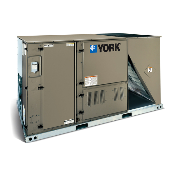
YORK ZT SERIES Rooftop Air Conditioner Manuals
Manuals and User Guides for YORK ZT SERIES Rooftop Air Conditioner. We have 3 YORK ZT SERIES Rooftop Air Conditioner manuals available for free PDF download: Technical Manual, Installation Manual
YORK ZT SERIES Technical Manual (148 pages)
3 - 12.5 TON Packaged Rooftop units
Brand: YORK
|
Category: Air Handlers
|
Size: 4 MB
Table of Contents
Advertisement


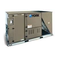
York ZT SERIES Technical Manual (65 pages)
Heating and Air Conditioning R-410A 3 - 5 TON 60 Hertz
Brand: York
|
Category: Air Conditioner
|
Size: 5 MB
Advertisement
Advertisement