Sign In
Upload
Manuals
Brands
York Manuals
Chiller
YCIV0307
York YCIV0307 Manuals
Manuals and User Guides for York YCIV0307. We have
1
York YCIV0307 manual available for free PDF download: Installation Operation & Maintenance
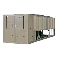
York YCIV0307 Installation Operation & Maintenance (334 pages)
Air-Cooled Screw Liquid Chillers
Brand:
York
| Category:
Chiller
| Size: 15.68 MB
Table of Contents
Table of Contents
6
Section 1 - General Chiller Information and Safety
15
Introduction
15
Warranty
15
Safety
15
About this Manual
16
Misuse of Equipment
16
Section 2 - Product Description
19
Introduction
19
Figure 1 - YCIV Chiller
19
Figure 2 - Chiller Control System
20
Figure 3 - Compressor
20
Figure 4 - PWM Current Waveform
25
Figure 5 - PWM Voltage Waveform
25
Accessories and Options
26
Complete PIN Number Description
29
Table 1 - Complete PIN Number Description
29
Section 3 - Rigging, Handling, and Storage
33
Lifting Weights
33
Delivery and Storage
33
Inspection
33
Moving the Chiller
34
Unit Removal from Shipping Container
34
Lifting Using Lugs
34
Lifting Using Shackles
34
Figure 6 - Lifting Lugs
34
Figure 7 - Lifting Using Lugs
34
Figure 8 - Unit Rigging
35
Table 2 - Lifting Points Dimensions
35
Section 4 - Installation
37
Location Requirements
37
Outdoor Installations
37
Indoor Installations
37
Location Clearances
37
Vibration Isolators
38
Shipping Braces
38
Chilled Liquid Piping
38
Water Treatment
39
Pipework Arrangement
40
Connection Types and Sizes
40
Cooler Connections
40
Refrigerant Relief Valve Piping
40
Figure 9 - Pipework Arrangement
40
Figure 10 - Grooved Nozzle
40
Figure 11 - Flange Attachment
40
Ductwork Connection
41
Electrical Connection
41
Power Wiring
42
Power Supply Wiring
42
115 VAC Control Supply Transformer
42
Control Panel Wiring
42
Volts Free Contacts
43
System Inputs
43
Section 5 - Commissioning
45
Preparation
45
Preparation - General
45
First Time Start-Up
46
Section 6 - Technical Data
55
Figure 12 - Pressure Drop through Two Circuit YCIV Evaporators Ft H
55
Figure 13 - Pressure Drop through Two Circuit YCIV Evaporators Kpa
56
Figure 14 - Pressure Drop through Three Circuit YCIV Evaporators Ft H
57
Figure 15 - Pressure Drop through Three Circuit YCIV Evaporators Kpa
58
Glycol Correction Factors
59
Figure 16 - Glycol Correction Factors
59
Table 3 - Water Temperature and Flows
60
Table 4 - Physical Data, English - Standard Efficiency
62
Table 5 - Physical Data (English - High Efficiency)
64
Table 6 - Physical Data, si - Standard Efficiency
66
Table 7 - Physical Data (si - High Efficiency)
68
Figure 17 - Two Compressor Wiring Diagram with Circuit Breaker
70
Figure 18 - Two Compressor Wiring Diagram with Terminal Block
70
Figure 19 - Three Compressor Wiring Diagram with Circuit Breaker - Single Point
71
Figure 20 - Three Compressor Wiring Diagram with Terminal Block - Single Point
71
Table 8 - Standard Efficiency 2-Compressor Units
72
Table 9 - High Efficiency 2-Compressor Units
76
Table 10 - Standard Efficiency 3-Compressor Units
81
Table 11 - High Efficiency 3-Compressor Units
82
Electrical Notes
84
Table 12 - Typical Compressor Starting Current (First Four Seconds of Start-Up)
84
Table 13 - Voltage Utilization Range
84
Electrical Wiring Diagrams - 2 Compressor Models
86
Figure 21 - Elementary Control Wiring Diagram 2 Compressor Models
86
Figure 22 - Elementary Power Wiring Diagram - YCIV0157-0267 2 Compressor Models
88
Figure 23 - Power Wiring Connection Diagram - YCIV0157-0267 2 Compressor Models
90
Figure 24 - Control Wiring Connection Diagram - YCIV0157-0267 2 Compressor Models
92
Figure 25 - Power Elementary Wiring Diagram - YCIV0157-0267 2 Compressor Models
95
Figure 26 - Location Label - 2 Compressor Models
97
Figure 27 - Panel Layout - 2 Compressor Models
98
Electrical Wiring Diagrams - 3 Compressor Models
100
Figure 28 - Control Elementary Diagram - YCIV0257-0397 3 Compressor Models
100
Figure 29 - Power Elementary Diagram - YCIV0257-0397 3 Compressor Models
104
Figure 30 - Control Wiring Connection Diagram - YCIV0257-0397 3 Compressor Models
106
Figure 31 - Power Wiring Connection Diagram - YCIV1050-1500 3 Compressor Models
110
Figure 32 - Power Elementary Diagram - YCIV0257-0397 3 Compressor Models
112
Figure 33 - Location Label - 3 Compressor Models
114
Figure 34 - Panel Layout - 3 Compressor Models
115
Dimensions - 2 and 3 Compressor si
116
Figure 35 - Dimensions, 2 and 3 Compressor SI, YCIV0157E/V and YCIV0157S/P/H
116
Figure 36 - Dimensions, 2 and 3 Compressor English, YCIV0157E/V and YCIV0157S/P/H
117
Figure 37 - Dimensions, 2 and 3 Compressor English, YCIV0177E/V, YCIV0177S/P/H, YCIV0187E/V, and
118
Figure 38 - Dimensions, 2 and 3 Compressor English, YCIV0197E/V, YCIV0207S/P/H, and YCIV0227S/P/H
120
Figure 39 - Dimensions, 2 and 3 Compressor English, YCIV0207E/V and YCIV0227E/V
122
Figure 40 - Dimensions, 2 and 3 Compressor English, YCIV0247S/P/H, YCIV0247E/V, and YCIV0267S/P/H
124
Figure 41 - Dimensions, 2 and 3 Compressor English, YCIV0267E/V, and YCIV0287S/P/H
126
Figure 42 - Dimensions, 2 and 3 Compressor English, YCIV0287E/V
128
Figure 43 - Dimensions, 2 and 3 Compressor English, YCIV0307S/P/H
130
Figure 44 - Dimensions, 2 and 3 Compressor English, YCIV0327E/V and YCIV0357S/P/H
132
Figure 45 - Dimensions, 2 and 3 Compressor English, YCIV0357E/V and YCIV0397S/P/H
134
Clearances
136
Figure 46 - Clearances
136
Isolator Information for Units Shipped on or after June 15, 2008
137
Figure 47 - Isolator Selection and Mounting Locations
137
Figure 55 - Isolator Selection and Mounting Locations
137
Table 14 - Isolator Locations and Point Loads
137
Figure 48 - Isolator Selection and Mounting Locations
138
Figure 49 - Isolator Selection and Mounting Locations
139
Figure 50 - Isolator Selection and Mounting Locations
140
Figure 51 - Isolator Selection and Mounting Locations
141
Figure 52 - Isolator Selection and Mounting Locations
142
Figure 53 - Isolator Selection and Mounting Locations
143
Figure 54 - Isolator Selection and Mounting Locations
144
Figure 56 - Isolator Selection and Mounting Locations
146
Figure 57 - Isolator Selection and Mounting Locations
147
Figure 58 - Isolator Selection and Mounting Locations
148
Figure 59 - Isolator Selection and Mounting Locations
149
Figure 60 - Isolator Selection and Mounting Locations
150
Figure 61 - Isolator Selection and Mounting Locations
151
Figure 62 - Isolator Selection and Mounting Locations
152
Table 15 - Isolator Cross Reference
153
Figure 63 - One Inch Deflection Isolator Specifications
154
Table 16 - One Inch Deflection Isolator Dimensions
154
Table 17 - One Inch Deflection Isolator Weights
154
Figure 64 - One Inch Deflection Isolator
155
Figure 65 - Durulene Isolator Specifications
156
Table 18 - Durulene Isolator Dimensions
156
Table 19 - Durulene Isolator Weights
156
Figure 66 - Durulene Isolator
157
Figure 67 - Seismic Isolator Specifications
158
Table 20 - Seismic Isolator Weights
158
Figure 68 - Seismic Isolator
159
Isolator Information for Units Shipped before June 15, 2008
160
Figure 69 - SLRS Seismic Isolator Specifications
160
Figure 70 - SLRS Seismic Isolator
160
Table 21 - SLRS Seismic Isolator Weights
160
Figure 71 - ND-X Neoprene Isolator Specifications
162
Table 22 - ND-X Neoprene Specifications
162
Figure 72 - CIP 1 In. Delfection Restrained Mounting Specifications
163
Table 23 - CIP 1 In. Deflection Restrained Mounting Specifications
163
Figure 73 - 1 In. Delfection Mounts
164
Refrigerant Flow Diagram
165
Figure 74 - Refrigerant Flow Diagram
165
Process and Instrumentation Diagram
166
Figure 75 - Process and Instrumentation Diagram
166
Component Locations
167
Figure 76 - Component Locations
167
Figure 77 - Control and VSD Cabinet Components
168
Figure 78 - Chiller Control Board, Relay Boards, Microgateway, and Optional Circuit Breaker
169
Figure 79 - Chiller Control Board, Relay Boards, and Microgateway, 2 Compressor
170
Figure 80 - Chiller Control Board, Relay Boards, and Microgateway, 3 Compressor
171
Figure 81 - VSD Logic Board
172
Figure 82 - VSD Logic Board (Original - Obsolete), P/N 031-02477-000
173
Figure 83 - VSD Logic Board (New), P/N 031-02507-XXX
174
Figure 84 - Power Components, 2 Compressor
175
Figure 85 - Power Components, 3 Compressor
176
Figure 86 - Fan Contactors and 3T Transformer, 2 Compressor
177
Figure 87 - Fan Contactors, 3 Compressor
178
Figure 88 - VSD Components
179
Figure 89 - VSD Components, 2 Compressor
180
Figure 90 - VSD Components, 3 Compressor
181
Figure 91 - VSD Components, 2 Compressor
182
Figure 92 - VSD Components, 3 Compressor
183
Figure 93 - Inverter Power Components, 2 Compressor
184
Figure 94 - Inverter Power Components, 3 Compressor
185
Figure 95 - Inverter Power Components
186
Glycol System Components
188
Figure 96 - Glycol Pump and Fill Tube Locations
188
Figure 97 - Glycol Piping and Fill Tube Location
189
Compressor Components
190
Figure 98 - Compressor Components
190
Chiller Electronic Components
191
Figure 99 - Keyboard and Display
191
Figure 100 - Cller Control Board
192
Figure 101 - Relay Output Boards
193
Figure 102 - AC to DC Rectifier
194
Figure 103 - SCR Trigger Board
194
Figure 104 - DC Link Filter Capciators
194
Figure 105 - Equalizing/Bleeder Resistors
195
Figure 106 - 1L Line Inductor
195
Figure 107 - IGBT Gate Driver Board
196
Figure 108 - Laminated Bus Structure
196
Figure 109 - New Board P/N 031-02507-000
196
Figure 110 - Obsolete Board P/N 031-02477-000
197
Figure 111 - Current Transformers
198
Figure 112 - DV/DT Output Suppression Network
198
Figure 113 - Flash Tank Feed and Drain Valve Controller
198
Chiller Configuration Jumpers
199
Figure 114 - DC Bus Voltage Isolation Board
199
Figure 115 - Chiller Circuit Breaker
199
Table 24 - Compressors and the Appropriate Jumper Positions
199
VSD Logic to Chiller Microprocessor Board RS-485 Communication Configuration Jumpers
200
Maximum VSD Frequency/Model Designator
200
Table 25 - VSD Logic Board Address Jumper
200
Table 26 - Maximum Frequency / Model Designator Jumper
200
Section 7 - Operation
201
Operating Controls
201
Basic Operating Sequence
202
Figure 116 - Unit Switch
202
Number of Compressors to Start
203
Figure 117 - Chiller Control (Cooling) Range
203
Minimum VSD Compressor Start / Run Frequency
204
Figure 118 - Number of Compressors to Start
204
Figure 119 - Minimum VSD Start Frequency
204
Acceleration / Deceleration Rate When Starting / Stopping Compressors
205
Standard IPLV Capacity Control
205
Figure 120 - Minimum VSD Run Frequency
205
Optional High IPLV Capacity Control
207
Table 27 - Fuzzy Logic Loading/Unloading Vs. Error
207
Table 28 - Fuzzy Logic Loading/Unloading Vs. Error
209
Load Limiting Control
210
Table 29 - Current Limit Load Limiting/Unloading
210
Table 30 - Discharge Pressure Load Limiting/Unloading
211
Table 31 - Suction Pressure Load Limiting/Unloading
211
Table 32 - VSD Internal Ambient Load Limiting/Unloading
211
Flash Tank Drain and Feed Valve Controller
212
Figure 121 - Flash Tank Drain and Feed Valve Controller
212
Table 33 - VSD Baseplate Temperature Load Limiting/Unloading
212
Figure 122 - LED Locations
214
Figure 123 - Power and Comms Led's
214
Figure 124 - Power, Comms and System Open/Close Led's
214
Economizer Control
215
Condenser Fan Control
216
Figure 125 - Condenser Fan Locations
216
Table 34 - Fan Stages and Corresponding Outputs
216
VSD Temperature Control, Operation of the Coolant Pump, and VSD Cabinet Cooling Fans
217
Figure 126 - Standard IPLV Fan Control
217
Figure 127 - High IPLV Fan Control
217
Remote Temperature Reset Control
218
Remote Current Limit Reset Control
219
Figure 139 - Program Key
219
Sound Limit Control
221
Section 8 - Micropanel
223
VSD Operation and Controls
223
Figure 128 - VSD Glycol Pump
225
Figure 129 - Original - Obsolete P/N 031-02477-000
225
Figure 130 - New Board - P/N 031-02507-XXX
226
VSD Safeties (Faults)
227
Table 35 - VSD Operating Display Parameters
227
Unit Warnings
233
Microboard (331-03478-XXX)
233
Figure 131 - Microboard 331-03478-XXX
234
Program Update
235
Data Logging
236
Table 36 - Flash Card Update Error XXXXX
236
Table 37 - Data Logging
236
Unit Safeties
237
System Safeties (Faults)
238
Table 38 - Low Differential Oil Pressure Cutout
241
Table 39 - Start Inhibit Sensor Thresholds
242
Status Key
244
Figure 132 - Status Key
244
Unit Data Key
247
Figure 133 - Unit Data Key
247
System Data Keys 1 through 4
249
Figure 134 - System Data Keys 1 through 4
249
Table 40 - Sensor Min./Max. Outputs
251
VSD Data Key
252
Figure 135 - VSD Data Key
252
Operating Hours / Start Counter Key
254
Figure 136 - Operating Hours / Start Counter Key
254
History Key
255
Figure 137 - History Key
255
Setpoints Key
262
Figure 138 - Setpoints Key
262
Table 41 - Setpoint Limits
263
Program Key
264
Table 42 - Programmable Operating Parameters
266
Options Key
267
Figure 140 - Options Key
267
Date / Time and Schedule Keys
270
Figure 141 - Date / Time and Schedule Keys
270
Manual Override Key
274
Figure 142 - Manual Override Key
274
Print Key
275
Figure 143 - Print Key
275
Table 43 - Printout Types
275
Service Key
278
Figure 144 - Service Key
278
System Switches Key
284
Figure 145 - System Switches Key
284
Serial Number Programming
285
Enabling Optimized High IPLV Mode
286
Unit Setup Mode
287
Table 44 - Unit Setup Programmable Values
287
Default Programmable Values
288
Serial Port Connections
288
Analog Input Connections
289
Table 45 - Serial Port Connections
289
Table 46 - Analog Input Connections
289
Digital Intput Connections
291
Table 47 - Digital Input Connections
291
Analog Output Connections
292
Table 48 - Analog Output Connections
292
Digital Output Connections
293
Table 49 - Digital Output Connections
293
BACNET, MODBUS and YORKTALK 2 Communications
295
Figure 146 - Control Board Connections
296
Table 50 - Minimum, Maximum and Default Values
296
Table 51 - Values Required for BAS Communication
297
Table 52 - Real Time Error Numbers
297
Table 53 - Bacnet and Modbus Communications Data Map
299
Section 9 - Maintenance
305
General Requirements
305
Figure 147 - Service Connections
306
Figure 148 - Service Connection View Showing Evaporator Inlet
306
Figure 149 - Leak Test Hold Times
307
Figure 150 - Evacuation of Chiller Operation
310
Table 54 - System Pressures
310
Figure 151 - Saturation Curve
311
Table 55 - R-134A Pressure to Saturated Temperature Conversion
314
Maintenance Requirements for YCIV Chillers
316
Table 56 - Troubleshooting Guide
317
Limited Warranty
319
Chilled Liquid and Suction Temperature Sensor Input Voltage
320
Table 57 - Temperature Input Voltage Sensor (Measured Signal to Shield at the Sensor)
320
Table 58 - Outside Air Temperature Sensor Input Voltage (Measured Signal to Shield at the Sensor)
321
Table 59 - Pressure Transducer Output Voltage (Measured Signal to Return at the Transducer)
322
Table 60 - Motor Temperature Sensor Resistance (Check at the Motor)
323
Table 61 - Compressor Motor Overload Settings and Maximum VSD Frequency
324
Printer Wiring
327
Figure 152 - Print Cable - Chiller to Serial Printer
327
Operating Log Sheet
329
Recommended Spare Parts
333
Table 62 - Recommended Spare Parts
333
Advertisement
Advertisement
Related Products
York Latitude YCIV0307P
York Latitude YCIV0307S
York YCIV0307S/P
York Latitude YCIV0357V
York Latitude YCIV0357S
York Latitude YCIV0397S
York YCIV0357S/P
York YCIV0327E/V
York YCIV0357E/V
York Latitude YCIV0327E
York Categories
Air Conditioner
Heat Pump
Chiller
Furnace
Air Handlers
More York Manuals
Login
Sign In
OR
Sign in with Facebook
Sign in with Google
Upload manual
Upload from disk
Upload from URL