Sign In
Upload
Manuals
Brands
YOKOGAWA Manuals
Control Unit
F3LR01-0N
YOKOGAWA F3LR01-0N Manuals
Manuals and User Guides for YOKOGAWA F3LR01-0N. We have
1
YOKOGAWA F3LR01-0N manual available for free PDF download: User Manual
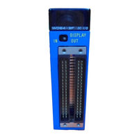
YOKOGAWA F3LR01-0N User Manual (210 pages)
Fiber-optic FA-bus Module / Fiber-optic FA-bus Type 2 Module / FA-bus Type 2 Module
Brand:
YOKOGAWA
| Category:
Control Unit
| Size: 8.82 MB
Table of Contents
Applicable Product
3
Precautions
4
Introduction
12
Copyrights and Trademarks
14
Table of Contents
15
PART-A Fiber-Optic FA-Bus Module (F3LR01-0N)
21
IM 34M06H45-01E 7Th Edition : Aug.30
21
A1. Overview
23
A1.1 Features
23
A1.2 Application Example
24
A2. Specifications
25
A2.1 Model and Suffix Codes
25
A2.2 Function Specifications
25
A2.3 Operating Environment
25
A2.4 Components and Their Functions
26
A2.5 External Dimensions
27
A3. System Configuration
29
A3.1 Fiber-Optic FA-Bus System Configuration
29
A3.1.2 Connection Topology
29
A4. Pre-Operation Setup and Cable Connection
31
A4.1 Startup Procedure
31
A4.2 Setting Switches
32
A4.2.1 Setting Unit Number Switch
32
A4.2.2 Setting Condition Switches
33
A4.3 Attaching and Detaching Modules
34
A4.3.3 Attaching Modules in Intense Vibration Environments
35
A4.3.4 Installation Depth
35
Connecting Fiber-Optic Cables
36
A4.4.1 Cable Preparation
36
A4.4.2 Attaching and Detaching Connectors
42
A4.4.3 Precautions When Connecting Fiber-Optic Cables
43
A4.5 Pre-Operation Checks
44
A4.5.2 LED Checks
45
A4.6 Precautions When Applying Power
46
A5. Accessing Modules in a Subunit
49
A5.1 Slot Number in FA-M3
49
A6. I/O Refresh Time
51
Estimating I/O Refresh Time
51
A6.2 an Example of I/O Refresh Time Calculation
52
A7. RAS Functions
53
A7.1 Error Location Detection Function
53
A7.1.1 LED Display
53
Shutdown Output on Transmission Channel Error Function
54
A7.2.1 Overview of Shutdown Output Function
54
A7.2.2 Shutdown Output of Subunit
54
A7.2.3 Procedure for Setting I/O Conditions
55
A8. Errors and Troubleshooting
59
A8.1 Troubleshooting Flowcharts
59
A8.2 When RDY LED Is Not Lit
60
A8.3 When ERR LED Is Lit
61
Index
63
Part-B Fiber-Optic FA-Bus Type 2 Module (F3LR02-0N)
65
B1. Overview
67
B1.1 Features
68
B2. Specifications
71
Model and Suffix Codes
71
B2.2 Function Specifications
71
B2.3 Operating Environment
71
Components and Their Functions
72
External Dimensions
73
B2.5 External Dimensions
73
B3. Fiber-Optic FA-Bus Type 2 System Configuration
75
B3.1 What Is a Substation
75
B3.2 Substation Configuration
76
System Configuration and Slot Numbers
77
Restrictions on System Configuration
80
Connection Topology
80
B3.6 System Configuration Design
84
Total Distance
85
B3.7 Total Distance
85
B3.8 Precautions When Changing Slot Number
86
B4. Pre-Operation Setup and Cable Connection
87
B4.1 Startup Procedure
87
B4.2 Setting Switches
88
B4.2.1 Setting Unit Number
89
B4.2.2 Setting Slot Number
89
Enabling/Disablingshutdown Output on
91
Transmission Channel Error Function
91
B4.2.4 Setting the Number of Ports
91
B4.2.5 Setting Transmission Channel Configuration
92
B4.2.6 Setting Light Intensity
92
B4.3 Attaching and Detaching Modules
93
Attaching the Module
93
Detaching the Module
93
B4.3.3 Attaching Modules in Intense Vibration Environments
94
B4.3.4 Installation Depth
94
Connecting Fiber-Optic Cables
95
B4.4.1 Cable Preparation
95
B4.4.2 Attaching and Detaching Connectors
101
B4.4.3 Precautions When Connecting Fiber-Optic Cables
102
B4.4.4 Connecting Fiber-Optic Cables
103
Pre-Operation Checks
105
B4.5.1 Checking Transmission Loss
105
B4.5.2 LED Checks
106
B4.6 Precautions When Applying Power
107
B5. I/O Refresh Time
109
Estimating I/O Refresh Time
109
B5.2 Example of I/O Refresh Time Calculation
110
B6. RAS Functions of Fiber-Optic FA-Bus Type 2
111
B6.1 System Operation with Transmission Channel Error
111
B6.1.1 Run or Stop System
111
B6.1.2 Causes of Transmission Channel Errors
111
Defining System Operation (Run or Stop) in the Event of a Transmission Channel Error
111
B6.1.4 Loop Switching
111
B6.1.5 Transmission Channel Loop-Back Function
114
B6.2 Shutdown Output on Transmission Channel Error Function
115
Overview of Shutdown Output Function
115
Shutdown Output Function Setup
115
B6.3 Procedure for Setting Condition Switches
118
Setting Condition Switches
118
B6.3.2 DIO Setup in CPU Configuration
119
B6.3.3 Operation Control in CPU Configuration
121
B6.4 Error Location Detection Function
122
B6.4.1 LED Display
122
B6.4.2 Logging of Transmission Channel Error Location
129
B7. Errors and Troubleshooting
135
B7.1 Troubleshooting Flowcharts
135
B7.2 When RDY LED Is Not Lit
136
B7.3 When ERR1 LED or ERR2 LED Is Lit
137
C1. Overview
143
C1.1 Features
144
C2. Specifications
145
Model and Suffix Codes
145
C2.2 Function Specifications
145
C2.3 Operating Environment
145
Components and Their Functions
146
C2.5 External Dimensions
147
C3. FA-Bus Type 2 System Configuration
149
C3.1 System Elements and Terminology
149
System Configuration and Slot Numbers
150
C3.3 Restrictions on System Configuration
152
Connection Topology
153
C3.4 Connection Topology
153
C4. Pre-Operation Setup and Cable Connection
157
C4.1 Startup Procedure
157
C4.2 Setting Switches
158
C4.2.1 Setting Unit Number
159
Enabling/Disabling Shutdown Output on Transmission Channel Error
160
C4.2.3 Setting the Number of Ports
160
C4.2.4 Setting Transmission Channel Configuration
161
C4.3 Attaching and Detaching Modules
162
C4.3.1 Attaching the Module
162
C4.3.2 Detaching the Module
162
C4.3.3 Attaching Modules in Intense Vibration Environments
163
Connecting Transmission Cables
164
C4.4.1 Cable Preparation
164
C4.4.2 Recommended Cables
164
C4.4.3 Wiring of Recommended Cables
165
C4.4.4 Usage Precautions for Fixed Cable (KM80)
166
C4.4.5 Usage Precautions for Flexible Cable (KM81)
167
C4.4.6 Provided Connectors
169
C4.5 Pre-Operation Checks
170
C4.5.1 LED Checks
170
C4.6 Precautions When Applying Power
171
C5. I/O Refresh Time
173
Estimating I/O Refresh Time
173
C5.2 Example of I/O Refresh Time Calculation
174
C6. RAS Functions of FA-Bus Type 2
175
C6.1 System Operation with Transmission Channel Error
175
Run or Stop System
175
Causes of Transmission Channel Errors
175
Defining System Operation (Run or Stop) in the Event of a Transmission Channel Error
175
Loop Switching
175
C6.1.5 Transmission Channel Loop-Back Function
178
C6.2 Shutdown Output on Transmission Channel Error Function
179
C6.2.1 Overview of Shutdown Output Function
179
C6.2.2 Shutdown Output Function Setup
179
C6.3 Procedure for Setting Condition Switches
182
Setting Condition Switches
182
C6.3.2 DIO Setup in CPU Configuration
183
C6.3.3 [Operation Control] in CPU Configuration
185
C6.4 Error Location Detection Function
186
C6.4.1 LED Display
186
C6.4.2 Logging of Transmission Channel Error Location
193
C7. Errors and Troubleshooting
199
C7.1 Troubleshooting Flowcharts
199
C7.2 When RDY LED Is Not Lit
200
C7.3 When ERR1 LED or ERR2 LED Is Lit
201
Appendix C: KM8 Cable Preparation
203
Index
207
Revision Information
209
Advertisement
Advertisement
Related Products
YOKOGAWA F3LR02-0N
YOKOGAWA F3LR02-1W
YOKOGAWA F3LP02-0N
YOKOGAWA F3LP12-0N
YOKOGAWA F3LH02-0N
YOKOGAWA F3LP32-0N
YOKOGAWA F3LA01-0N
YOKOGAWA F3RS22-0N
YOKOGAWA F3RS41-0N
YOKOGAWA F3YP14-0N
YOKOGAWA Categories
Measuring Instruments
Test Equipment
Transmitter
Controller
Media Converter
More YOKOGAWA Manuals
Login
Sign In
OR
Sign in with Facebook
Sign in with Google
Upload manual
Upload from disk
Upload from URL