Sign In
Upload
Manuals
Brands
YOKOGAWA Manuals
Control Unit
F3LP12-0N
YOKOGAWA F3LP12-0N Manuals
Manuals and User Guides for YOKOGAWA F3LP12-0N. We have
1
YOKOGAWA F3LP12-0N manual available for free PDF download: User Manual
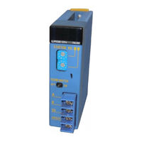
YOKOGAWA F3LP12-0N User Manual (108 pages)
Brand:
YOKOGAWA
| Category:
Control Unit
| Size: 4 MB
Table of Contents
Applicable Product
3
Precautions
4
Introduction
12
Copyrights and Trademarks
14
Table of Contents
15
1 Overview
19
F3LP02-0N and F3LP12-0N Modules
19
Link Device
19
Operation Mode
19
System Configuration
20
Single-Layer System
20
Multi-Layer System
21
RAS Function
22
2 Specifications
23
Model Names and Specification Codes
23
Operating Environment
23
Performance Specifications
23
Cable Specifications
24
Specifications of Twisted Pair Cables
24
Specifications for Fiber Optic Cables
24
External Dimensions
30
F3Lp02-0N
30
F3Lp12-0N
30
3 Setup and Connection of Modules
31
Startup Procedures
31
Components and Their Functions
32
F3Lp02-0N
32
F3Lp12-0N
33
Setting Station Numbers
34
Setting Parameters
35
F3Lp02-0N
35
F3Lp12-0N
35
Setting Operation Mode
35
Attaching and Detaching Modules
36
Wiring
38
F3Lp02-0N
38
F3Lp12-0N
39
Applying the Power
42
F3Lp02-0N
42
F3Lp12-0N
42
Checking Communication Status
43
FA Link Module Status
44
Displaying Status of Local Station
45
Displaying Status of Remote Stations
47
Configuration Setup of CPU Module
49
Setting Device Capacities
50
For High Speed Mode
51
For Normal Mode
53
Setting FA Link System Numbers
56
FA Link H Configuration
61
4 Link Data Configuration
73
Link Relays
73
Link Registers
74
Special Relays
75
Special Registers
78
5 Operation and Processing Time
79
Overview of Data Link Processing
79
Link Refresh
80
Link Refresh Range
82
Cyclic Transmission
83
Response Time
84
Response Time of a Single Layer System
84
6 Cautions on Using FA Link H Modules
85
Operation Mode
85
CPU Module Configuration Setup
85
Multi-CPU System
85
Programming Precautions
86
Checking Link Data Allocation
86
Precautions When Setting Station Numbers
86
Powering on
86
When a Slave Station Fails
87
When Connecting FA Link H Module to FA500 or Μfa20
87
When Intermixing Old and New Modules Within the same System
87
7 High-Speed Mode
91
CPU Module Configuration
91
Setting Device Capacity
91
FA Link H Configuration
93
Link Data Configuration
94
Link Relays
94
Link Registers
95
Response Time
96
Response Time of Layered System
96
Restrictions on Mixing Modes (Normal and High-Speed) in Link Systems
97
8 Troubleshooting
99
When "RDY" LED Is off
100
When "ERR" LED Is Lit
101
When Communication Cannot Proceed
102
Error Codes When Using Widefield3
103
Index
105
Revision Information
107
Advertisement
Advertisement
Related Products
YOKOGAWA F3LP02-0N
YOKOGAWA F3LP32-0N
YOKOGAWA F3LR02-0N
YOKOGAWA F3LR01-0N
YOKOGAWA F3LR02-1W
YOKOGAWA F3LH02-0N
YOKOGAWA F3LA01-0N
YOKOGAWA F3RS22-0N
YOKOGAWA F3RS41-0N
YOKOGAWA F3YP14-0N
YOKOGAWA Categories
Measuring Instruments
Test Equipment
Transmitter
Controller
Media Converter
More YOKOGAWA Manuals
Login
Sign In
OR
Sign in with Facebook
Sign in with Google
Upload manual
Upload from disk
Upload from URL