Sign In
Upload
Manuals
Brands
YOKOGAWA Manuals
Control Unit
F3CU04-0S
YOKOGAWA F3CU04-0S Manuals
Manuals and User Guides for YOKOGAWA F3CU04-0S. We have
1
YOKOGAWA F3CU04-0S manual available for free PDF download: User Manual
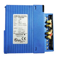
YOKOGAWA F3CU04-0S User Manual (260 pages)
Temperature Control and PID Module
Brand:
YOKOGAWA
| Category:
Control Unit
| Size: 4.08 MB
Table of Contents
Applicable Product
3
Important
4
Introduction
11
Copyrights and Trademarks
12
Table of Contents
13
PART-A Function Overview
17
IM 34M06H62-02E 3Rd Edition : Jul.16
17
A1 Overview
19
A2 Specifications
21
A2.1 Model and Suffix Codes
21
A2.2 Compatibility with CPU Modules
21
A2.3 General Specifications
22
A2.4 Input Specifications
22
A2.5 Output Specifications
27
A2.6 Backup Function
27
A2.7 Function Specifications
28
A2.8 Components and Functions
30
A2.9 External Dimensions
31
A3 Startup Procedure
33
A4 Hardware Preparation
35
A4.1 Selecting Input Types and Power Frequency
36
A4.2 Attaching/Detaching Modules
40
A4.3 Wiring
42
A4.3.1 Wiring Precautions
42
A4.3.2 Terminal Wiring Diagram
44
PART-B Parameter Description
49
B1 Accessing the Module
51
Accessing Using Sequence Instructions
52
B1.2 Accessing Using BASIC
55
B1.3 Writing and Reading after Powering on
56
B2 Types of Relays and Registers
57
B2.1 Types of Relays
57
B2.2 Types of Registers
58
B2.2.1 Common Process Data
60
B2.2.2 Analog Output Settings
61
B2.2.3 Setup Control Parameters
62
B2.2.4 SP Backup Parameters
63
B2.2.5 Function Control Parameters
63
B2.2.6 EEPROM Write Counter
63
B2.2.7 Controller Parameters
64
B2.2.8 Process Data
66
B2.2.9 Operation Control Parameters
68
B2.2.10 I/O Parameters
69
B2.2.11 Operation Parameters
71
B2.3 How to Enable Settings
76
How to Back up SP Values to EEPROM
87
B2.5 Initializing All Settings
89
B3 Setup and Operation
91
Setting Controller Parameters
92
B3.1.1 Power Frequency Selection
92
B3.1.2 Input Sampling Period
92
B3.1.3 Controller Mode
93
B3.1.4 Setting Output Terminals
95
B3.1.5 Sample Program for Setting Controller Parameters
96
B3.2 Setting I/O Parameters
98
B3.2.1 Input Type Selection
98
B3.2.2 Control Type Selection
98
B3.2.3 Sample Program for Setting I/O Parameters
99
Setting Operation Parameters
102
B3.3.1 Preparing for Dynamic Auto-Tuning
102
B3.3.2 Preparing for PID Control
104
B3.3.3 Sample Program for Setting Operation Parameters
106
B3.4 Operation
108
B4 Sample Program
109
PART-C Function Description
117
C1 Controller Mode
119
C1.1 Single Loop
120
C1.2 Cascade Control
122
Cascade Control Operation
124
C1.3 Two-Input Changeover Control
126
C1.4 Disabled Mode
129
C2 Output-Related Functions
131
Control Type Selection
135
Output Type Selection
135
C2.3 Output Terminal Selection
136
Control Types and Their Operations
137
C2.4.1 ON/OFF Control Output
137
C2.4.2 PID Control Output
139
C2.4.3 Heating/Cooling PID Control
143
C2.4.4 Heating/Cooling ON/OFF Control
151
C2.5 Analog Output
153
C2.6 External Output
154
C3 PV-Related Functions
155
C3.1 Input Type Selection
158
C3.2 Power Frequency Selection
161
C3.3 Input Range Setting
162
C3.4 PV Range Setting (for Use in Two-Input Changeover Mode Only)
163
C3.5 Burnout Detection
164
C3.6 Reference Junction Compensation
165
Broken-Line Biasing
166
C3.8 Fixed Biasing
167
C3.9 Square Root Extraction
168
C3.10 Input Filtering
169
C3.11 Two-Input Changeover
170
C3.12 External Input
172
C4 SP-Related Functions
173
C4.1 Set Point (SP)
174
C4.2 Remote Set Point
175
C4.3 Limiting the Set Point
176
C4.4 Setting SP Gradient
177
C4.5 PV Tracking
179
C4.6 SP Tracking
180
C5 Auto-Tuning Function
181
C5.1 Dynamic Auto-Tuning
181
C5.2 Auto-Tuning
183
C5.2.1 Tuning Points and Stored PID Number
185
C6 Control and Computation Function
187
C6.1 Forward Operation and Reverse Operation
187
Proportional Band
188
C6.2 Proportional Band
188
Integral Time and Manual Reset Values
190
C6.4 Derivative Time
192
C6.5 Manual Adjustment PID Constants
194
C6.6 PID Control Mode
195
C6.7 "Super" Overshooting Suppression Function
197
C6.8 Anti-Reset Windup
198
C6.9 PID Selection Method (SP Number Selection, Zone PID Selection)
199
C6.9.1 SP Number Selection
200
C6.9.2 Zone PID Selection
201
C7 Operation Control
205
C7.1 Run/Stop Switch
205
C7.1.1 Operation after Switching from Stop Mode to Run Mode
206
C7.2 Automatic/Manual Switch
208
C7.2.1 Operation after Switching from Manual Mode to Automatic
209
Mode
209
C7.3 Remote/Local Switch
210
C7.4 Automatic/Manual/Cascade Switch
211
C7.4.1 Cascade Mode
212
C7.4.2 Automatic Mode
212
C7.4.3 Manual Mode
213
C7.5 Preset Output Function
214
C8 Alarm Function
215
C8.1 Alarm Types
218
C8.2 Wait Function
220
C8.3 Alarm Delay Timer
221
C8.4 Selecting Alarm Preset Values
221
C9 Disable Backup Function
223
C10 Self-Diagnosis Function
225
C10.1 How to Check for Errors
226
C10.2 List of Error Statuses
226
C11 Selecting Temperature Unit
229
PART-D Troubleshooting
231
D1 before Performing Checks
233
D2 Troubleshooting a Specific Problem
235
Input Does Not Change, or Fluctuates Excessively
236
Any LED Indicator Other than RDY and 60 Hz Is Lit or Flashing
237
The Loop Is out of Control (with an Oscillating Response)
238
Output Does Not Respond to or Follow a Changed Set Point Value
239
Excessive Overshooting
239
Settings Are Not Enabled
239
PART-E Relays and Registers
241
E1 List of Registers
243
E2 List of Relays
253
Index
255
Revision Information
257
Advertisement
Advertisement
Related Products
YOKOGAWA F3CU04-1S
YOKOGAWA FA-M3 VITESSE F3CX04-0N
YOKOGAWA F3RS22-0N
YOKOGAWA F3RS41-0N
YOKOGAWA F3YP18-0N
YOKOGAWA F3LR02-0N
YOKOGAWA F3LR01-0N
YOKOGAWA F3LR02-1W
YOKOGAWA F3LP12-0N
YOKOGAWA F3LH02-0N
YOKOGAWA Categories
Measuring Instruments
Test Equipment
Transmitter
Controller
Media Converter
More YOKOGAWA Manuals
Login
Sign In
OR
Sign in with Facebook
Sign in with Google
Upload manual
Upload from disk
Upload from URL