Sign In
Upload
Manuals
Brands
YOKOGAWA Manuals
Test Equipment
DLM4038
YOKOGAWA DLM4038 Manuals
Manuals and User Guides for YOKOGAWA DLM4038. We have
2
YOKOGAWA DLM4038 manuals available for free PDF download: User Manual, Getting Started Manual
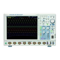
YOKOGAWA DLM4038 User Manual (373 pages)
DLM4000 Series, Mixed Signal Oscilloscope Communication Interface
Brand:
YOKOGAWA
| Category:
Recording Equipment
| Size: 5 MB
Table of Contents
List of Manuals
2
How to Use this Manual
4
Conventions Used in this Manual
5
Table of Contents
6
Chapter 1 USB Interface
8
Component Names and Functions
8
Front Panel
8
Rear Panel
8
USB Interface Features and Specifications
9
USB Interface Connection
11
Configuring the DLM4000 USB Settings
12
Chapter 2 Ethernet Interface
13
Component Names and Functions
13
Ethernet Interface Features and Specifications
14
Ethernet Interface Connection
16
Configuring the DLM4000 Network Settings
17
Chapter 3 GP-IB Interface (Option)
18
Component Names and Functions
18
Connecting GP-IB Cables
19
GP-IB Interface Features
20
GP-IB Interface Specifications
21
Functional Specifications
21
App
22
Configuring the DLM4000 GP-IB Settings
22
Responses to Interface Messages
23
Chapter 4 Programming Overview Index
25
Messages
25
Commands
27
Responses
29
Data
30
Synchronization with the Controller
32
Chapter 5 Commands
34
List of Commands
34
Acquire Group
94
Analysis Group
95
Asetup Group
112
Calibrate Group
113
Channel Group
114
Chutil Group
117
Clear Group
118
Communicate Group
119
Cursor Group
121
Display Group
128
FFT Group
130
FILE Group
137
Gonogo Group
141
Hcopy Group
147
History Group
150
Image Group
155
Initialize Group
156
Logic Group
157
MATH Group
166
Measure Group
171
Recall Group
181
Reference Group
182
Search Group
183
Serialbus Group
189
SNAP Group
269
Sstart Group
270
Start Group
271
Status Group
272
STOP Group
273
Store Group
274
System Group
275
Timebase Group
278
Trigger Group
279
Waveform Group
343
Wparameter Group
346
XY Group
350
ZOOM Group
353
Common Command Group
355
Chapter 6 Status Reports
358
About Status Reports
358
Status Byte
360
Standard Event Register
361
Extended Event Register
362
Output and Error Queues
363
Appendix 2 Error Messages
366
Appendix 1 ASCII Character Codes
367
Error Messages
367
Appendix 3
368
Index
368
Appendix 3 about the IEEE 488.2-1992 Standard
369
Advertisement
YOKOGAWA DLM4038 Getting Started Manual (109 pages)
Mixed Signal Oscilloscope, DLM4000 Series
Brand:
YOKOGAWA
| Category:
Test Equipment
| Size: 8 MB
Table of Contents
Product Registration
2
Checking the Contents of the Package
5
Standard Accessories
6
Safety Precautions
10
Sales in each Country or Region
14
Waste Electrical and Electronic Equipment
14
Conventions Used in this Manual
15
Table of Contents
16
Chapter 1 Component Names and Functions
18
Top Panel, Front Panel, Right Side Panel, Left Side Panel, and Rear Panel
18
Keys and Knobs
21
Display Key
24
Measure Key
25
Utility Key
26
Screens
28
Chapter 2 Making Preparations for Measurements
31
Handling Precautions
31
Installing the Instrument
33
Connecting the Power Supply and Turning the Power Switch on and off
36
Connecting Probes
39
Correcting a Probe Phase
44
Connecting Logic Probes
46
Attaching the Panel Sheet
48
Loading Roll Paper into the Built-In Printer (Option)
49
Chapter 3 Common Operations
51
Key and Jog Shuttle Operations
51
Entering Values and Strings
53
Using USB Keyboards and Mouse Devices
55
Synchronizing the Clock
61
Performing Auto Setup
62
Resetting the DLM4000 to Its Factory Default Settings
64
Calibrating the DLM4000
65
Starting and Stopping Waveform Acquisition
66
Displaying Help
67
Chapter 4 Rear Panel Input and Output
68
External Trigger Input (TRIGGER IN)
68
Trigger Output (TRIGGER OUT)
69
Video Signal Output (VIDEO out (XGA))
71
GO/NO-GO Signal Output
72
Chapter 5 Troubleshooting, Maintenance, and Inspection
74
If a Problem Occurs
74
Recommended Part Replacement
75
Chapter 6 Specifications
76
Signal Input Section
76
Triggering Section
79
Time Axis
83
Display
83
Features
84
Built-In Printer (/B5 Option)
89
Other Features
90
Storage
91
USB Ports for Peripherals
91
Auxiliary I/O Section
92
6.10 Computer Interface
93
6.11 General Specifications
94
6.12 External Dimensions
97
Appendix
98
Appendix 1 Relationship between the Time Axis Setting, Record Length, and Sample Rate
99
Appendix 2 USB Keyboard Key Assignments
109
Advertisement
Related Products
YOKOGAWA DLM4000 Series
YOKOGAWA DLM4058
YOKOGAWA DLM2000 Series
YOKOGAWA DLM3054
YOKOGAWA DLM3024
YOKOGAWA DLM3034
YOKOGAWA DLM5054
YOKOGAWA DLM2022
YOKOGAWA DLM2032
YOKOGAWA DLM2024
YOKOGAWA Categories
Measuring Instruments
Test Equipment
Transmitter
Controller
Media Converter
More YOKOGAWA Manuals
Login
Sign In
OR
Sign in with Facebook
Sign in with Google
Upload manual
Upload from disk
Upload from URL