Sign In
Upload
Manuals
Brands
YOKOGAWA Manuals
Test Equipment
DLM3024
YOKOGAWA DLM3024 Manuals
Manuals and User Guides for YOKOGAWA DLM3024. We have
3
YOKOGAWA DLM3024 manuals available for free PDF download: User Manual
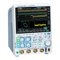
YOKOGAWA DLM3024 User Manual (284 pages)
Digital&Mixed Signal
Brand:
YOKOGAWA
| Category:
Test Equipment
| Size: 3 MB
Table of Contents
Manuals
3
Table of Contents
4
1 Vertical Axis (Analog Signal)
10
Turning the Display on and off (Display)
10
Vertical Scale (SCALE Knob)
10
Waveform Vertical Position (POSITION Knob)
11
Input Coupling (Coupling)
12
Probe Attenuation (Probe)
12
Inverted Waveform Display (Invert)
13
Linear Scaling (Linearscale)
13
Label Display (Label)
14
Bandwidth Limit (Bandwidth)
14
Offset (Offset)
14
2 Vertical Axis (Logic Signal)
16
Turning the Display on and off (Display)
16
Vertical Display Range (SCALE Knob)
16
Vertical Position (POSITION Knob)
16
Setting the Bits (Bit Setup)
16
Bus Display (Bus)
18
State Display (State)
19
Setting the Display Order of Bits and the Bus (Bit Order)
20
Deskew (Deskew)
20
3 Horizontal Axis (Time Axis)
21
Time Scale (TIME/DIV Knob)
21
4 Triggering
23
Trigger Mode (Trigger Mode)
23
Trigger Type (Type)
24
Signal Type and Trigger Type Combinations
25
Basic Trigger Settings
26
Edge Trigger [EDGE]
26
Edge or Trigger [ENHANCED]
30
Pattern Trigger [ENHANCED]
31
Pulse Width Trigger [ENHANCED]
35
Rise/Fall Time Trigger [ENHANCED]
36
Runt Trigger [ENHANCED]
38
Timeout Trigger [ENHANCED]
39
Window Trigger [ENHANCED]
40
Window or Trigger [ENHANCED]
42
Interval Trigger [ENHANCED]
43
Serial Bus Trigger [ENHANCED]
45
Flexray Bus Trigger [ENHANCED, Option]
46
CAN Bus Trigger [ENHANCED, Option]
52
CAN FD Bus Trigger [ENHANCED, Option]
60
LIN Bus Trigger [ENHANCED, Option]
66
CXPI Bus Trigger [ENHANCED, Option]
70
SENT Trigger [ENHANCED, Option]
78
UART Trigger [ENHANCED, Option]
84
I 2 C Bus Trigger [ENHANCED, Option]
86
SPI Bus Trigger [ENHANCED, Option]
91
User-Defined Serial Bus Trigger [User Define, ENHANCED]
94
TV Trigger [ENHANCED]
96
Trigger B [B TRIG]
99
5 Executing Actions
101
Action Mode (Mode)
101
Action to Execute When Conditions Are Met (Action)
101
Number of Actions (Action Count/Nogo Count)
102
Executing Action-On-Trigger or GO/NO-GO Determination (Exec)
103
GO/NO-GO Determination (Go/Nogo AND, Go/Nogo OR)
103
Notes about Action
107
6 Waveform Acquisition
108
Record Length (Record Length)
108
Acquisition Mode (Mode)
109
High Resolution Mode (Hi Resolution)
110
Sampling Mode (Sampling Mode)
111
Waveform Acquisition (RUN/STOP)
112
Acquiring the Waveform Once (SINGLE)
112
7 Display
113
Types of Windows
113
Display Format (Format)
113
Display Interpolation (Dot Connect)
114
Graticule (Graticule)
115
Scale Value Display (Scale Value)
115
Waveform Intensity (Intensity)
115
Accumulation (Accumulate)
116
8 Displaying XY Waveforms
117
Turning the XY Waveform Display on and off (Display)
117
X-Axis and Y-Axis Source Waveforms (X Trace/Y Trace)
117
Configuring the Display (Display Setup)
117
Display Source Window (Time Range)
118
Display Area (T Range1/T Range2)
118
Measurement (Measure Setup)
118
9 Computed and Reference Waveforms
119
Computation Mode (Mode)
119
Computation Source Waveforms (Source1/Source2)
119
Reference Waveforms
120
Operators (Operation)
121
Initial Point (Initial Point)
124
Setting Labels and Units (Label/Unit)
124
Scaling (Ranging)
125
User-Defined Computation (User Define, Option)
125
10 Fft
132
Turning the FFT on or off (Display)
132
Analysis Source Waveform (Trace)
132
FFT Conditions (FFT Setup)
133
Number of FFT Points (FFT Point)
134
Analysis Range (Time Range)
134
Scale Value (Display Setup)
135
Cursor Measurement (Measure Setup)
135
11 Cursor Measurement
137
Turning Cursor Measurement on and off (Display)
137
Cursor Mode (Type)
137
Measurement Source Waveform (Trace)
137
ΔT Cursors (ΔT)
138
ΔV Cursors (ΔV)
138
ΔT&ΔV Cursors (ΔT&ΔV)
139
Marker Cursors (Marker)
139
Angle Cursors (Degree)
140
Moving the Cursors (Cursor/Marker)
140
Cursor Jumping (Cursor Jump/T Cursor Jump)
141
12 Automated Measurement of Waveform Parameters
142
Turning Automated Measurement on or off (Mode)
142
Source Window (Time Range)
142
Measurement Time Period (T Range1/T Range2)
142
Statistics (Statistics)
148
Enhanced Parameter Measurement (Enhanced)
153
Notes about Automated Measurement of Waveform Parameters
154
13 Zooming in on Waveforms
155
Turning the Zoom Windows on or off (Display)
155
Display Format (Format)
155
Displaying the Main Window (Main)
156
Auto Scrolling (Auto Scroll)
156
Zoom Source Waveforms (Trace)
156
Zoom Factor (ZOOM Knob)
156
Zoom Position (Z1 Position, Z2 Position)
157
Vertical Zoom (Vertical Zoom)
157
14 Searching Waveforms
158
Search Source Waveform
158
Search Type (Type)
158
Search Conditions (Condition Setup)
161
Displaying Detected Waveforms (Display Setup)
164
Search Skip (Skip Mode)
164
Search Range (Start/End Point)
165
Detected Point Number (Pattern No.)
165
Executing a Search (Search)
165
15 Analyzing and Searching Serial Bus Signals
166
Turning the Analysis and Search Feature on or off (Display)
166
Serial Bus Signal Type (Type)
167
Bus Setup (Setup)
167
Search Setup (Search)
167
Zoom Position (Z1 Position, Z2 Position)
168
Decoded Display (Decode)
168
List Display (List)
169
Trend Display (Trend)
169
Saving the Analysis Results
169
Analyzing and Searching Flexray Bus Signals (Option)
170
Analyzing and Searching CAN Bus Signals (Option)
172
Analyzing and Searching CAN FD Bus Signals (Option)
174
Analyzing and Searching LIN Bus Signals (Option)
179
Analyzing and Searching CXPI Bus Signals (Option)
182
Analyzing and Searching SENT Signals (Option)
188
Analyzing and Searching UART Signals (Option)
193
C Bus Signals (Option)
196
Analyzing and Searching SPI Bus Signals (Option)
198
Analyzing and Searching User-Defined Serial Bus Signals (User Define)
200
16 Waveform Histogram Display
201
Turning the Histograms on or off (Display)
201
Source Waveform (Trace)
201
Source Axis (Type)
201
Range Setup (Range Setup)
201
Measurement (Measure Setup)
202
17 Power Supply Analysis Feature (Power Analysis and Power Measurement, Option)
203
Overview of the Power Supply Analysis Feature
203
Switching Loss Analysis (SW Loss)
204
Safe Operating Area Analysis (SOA)
209
Harmonic Analysis (Harmonics)
210
Measuring Inrush Current by Computing the Joule Integral (I 2 T)
214
Power Measurement (Power Measurement)
216
18 Displaying and Searching History Waveforms
220
Display Mode (Mode)
221
Average (Average)
221
Highlighting (Select No.)
221
Display Range (Start/End No.)
221
List of Timestamps (List)
221
Searching History Waveforms (Search)
222
Replay (Replay)
223
Notes on Using the History Feature
223
19 Printing and Saving Screen Captures
224
Destination Type (Print To)
224
Printing on the Built-In Printer (Builtin) (Option)
225
Printing on a USB Printer (USB)
225
Printing on a Network Printer (Network)
227
Saving Screen Captures to Files (File)
228
Printing and Saving Screen Captures to Multiple Destinations (Multi)
230
20 Saving and Loading Data
231
Storage Device You Can Save and Load from
231
Saving Data (Save)
232
Saving Waveform Data (Waveform)
232
Saving Setup Data (Setup)
235
Saving Other Types of Data (Others)
235
Serial Bus Analysis Results (Others - Serial Bus (Flexray/Can/Can FD/LIN/CXPI))
238
Serial Bus Analysis Results
238
C/Spi))
241
Loading Data (Load)
244
File Operations (Utility)
246
21 Ethernet Communication (Network)
248
Tcp/Ip(Tcp/Ip)
249
FTP Server (FTP Server)
250
Mail (Mail)
251
Network Drive (Net Drive)
252
Network Printer (Net Print)
253
Sntp (Sntp)
253
22 Other Features
254
Auto Setup (AUTO SETUP)
254
Default Settings (DEFAULT SETUP)
255
Snapshot (SNAP SHOT)
255
Clear Trace (CLEAR TRACE)
256
Calibration (Calibration)
256
Remote Control (Remote Control)
257
System Configuration (System Configuration)
259
Overview (Overview)
262
Self-Test (Self Test)
263
Touch Panel (TOUCH)
263
Appendix
264
Appendix 2 User-Defined Computation
266
FFT Function
270
Appendix 3 ASCII Data File Format
273
Appendix 4 TCP and UDP Port Numbers
274
Appendix 5 How Power Measurement Items Are Determined
275
Appendix 6 Trigger and Detected Points of SENT Signals
276
Appendix 7 Firmware Version and New Features
277
Index
278
Advertisement
YOKOGAWA DLM3024 User Manual (280 pages)
Digital Oscilloscope, Mixed Signal Oscilloscope
Brand:
YOKOGAWA
| Category:
Test Equipment
| Size: 9 MB
Table of Contents
Manuals
3
DLM Models and Conventions Used in this Manual
4
Table of Contents
5
Chapter 1 Vertical and Horizontal Control
9
Setting the Vertical Axis (Analog Signal)
9
Setting the Vertical Axis (Logic Signal) (on Models with the Logic Signal Input Port)
14
Setting the Horizontal Scale (Time Scale)
21
Chapter 2 Trigger
22
Setting the Trigger Mode and Trigger Hold-Off Time
22
Setting the Trigger Position and Trigger Delay
23
Edge Trigger
25
Triggering on an Edge Trigger
25
Triggering on the or of Multiple Edge Triggers
27
Triggering on Multiple Input Patterns
28
Triggering on Pulse Width
32
Triggering on Rise and Fall Times
34
Triggering on Runt Signals
36
Triggering on Timeout Period
38
Triggering on a Window Trigger
39
Triggering on the or of Multiple Window Triggers
41
Triggering on Edge Intervals
42
Triggering on Flexray Bus Signals (Option)
44
Triggering on CAN Bus Signals (Option)
47
Triggering on CAN FD Bus Signals (Option)
52
Triggering on LIN Bus Signals (Option)
58
Triggering on CXPI Bus Signals (Option)
62
Triggering on SENT Signals (Option)
67
Triggering on UART Signals (Option)
74
Triggering on I C Bus Signals (Option)
78
Triggering on I 2 C Bus Signals (Option)
79
Triggering on SPI Bus Signals (Option)
83
Triggering on User-Defined Serial Bus Signals
87
Triggering on a TV Trigger
90
Triggering on Combination Triggers (B TRIG)
92
Forcing the Instrument to Trigger (FORCE TRIG)
94
Setting the Action-On-Trigger Function
95
Performing GO/NO-GO Determination
96
Chapter 3 Waveform Acquisition
103
Setting Conditions for Waveform Acquisition
103
Acquiring Waveforms
105
Chapter 4 Screen Display
106
Setting Display Conditions
106
Using the Accumulate Feature
108
Using the Snapshot and Clear Trace Features
109
Adjusting the Backlight
110
Chapter 5 XY Display
111
Displaying XY Waveforms
111
Performing Cursor Measurements and Area Calculations
112
Chapter 6 Computed and Reference Waveforms
113
Setting the Computation Mode
113
Performing Addition, Subtraction, and Multiplication
114
Performing Filter Functions
115
Performing Integration
117
Performing Count Computations
118
Setting Labels, Units, and Scaling
120
Loading Reference Waveforms
121
Performing User-Defined Computations (Optional)
123
Chapter 7 FFT
126
Displaying FFT Waveforms
126
Measuring FFT Waveforms
128
Chapter 8 Cursor Measurement
128
Measuring with ΔT Cursors
130
Measuring with ΔV Cursors
131
Measuring with ΔT and ΔV Cursors
132
Measuring with Marker Cursors (Marker)
133
Measuring with Angle Cursors (Degree)
134
Chapter 9 Automated Measurement of Waveform Parameters
136
Automatically Measuring Waveform Parameters
137
Processing Statistics on Automatically Measured Values
140
Measuring Enhanced Parameters
145
Chapter 10 Zooming in or out of Waveforms
146
Zooming in or out of Waveforms
146
Zooming in or out of Waveforms in the Vertical Direction
148
Chapter 11 Searching Waveforms
149
Searching for Edges
149
Searching with Multiple Input Patterns
152
Searching for Pulse Width
156
Searching for Timeout Periods
159
Chapter 12 Analyzing and Searching Serial Bus Signals
161
Analyzing and Searching Flexray Bus Signals (Option)
161
Analyzing and Searching CAN Bus Signals (Option)
165
Analyzing and Searching CAN FD Bus Signals (Option)
169
Analyzing and Searching LIN Bus Signals (Option)
173
Analyzing and Searching CXPI Bus Signals (Option)
177
Analyzing and Searching SENT Signals (Option)
182
Analyzing and Searching UART Signals (Option)
189
Analyzing and Searching I2C Bus Signals (Option)
196
Analyzing and Searching SPI Bus Signals (Option)
200
Analyzing and Searching User-Defined Serial Bus Signals
207
Displaying Multiple Lists
212
Chapter 13 Waveform Histogram Display
213
Displaying Waveform Histograms
213
Measuring Histogram Parameters
214
Chapter 14 Power Supply Analysis
215
Power Supply Analysis Type
215
Analyzing Switching Loss
216
Performing Safe Operating Area Analysis
219
Performing Harmonic Analysis
220
Measuring the Joule Integral
223
Measuring Power
224
Chapter 15 Displaying and Searching History Waveforms
228
Displaying History Waveforms
228
Searching History Waveforms
231
Chapter 16 Printing and Saving Screen Captures
233
Loading Roll Paper into the Built-In Printer (Option)
233
Printing on the Built-In Printer (Option)
235
Printing on a USB Printer
236
Printing on a Network Printer
237
Saving Screen Captures to Files
238
Printing and Saving Screen Capture Data to Multiple Output Destinations at the same Time
240
Chapter 17 Saving and Loading Data
241
Connecting USB Storage Device to the USB Ports
241
Saving Waveform Data
242
Saving Setup Data
246
Saving Other Types of Data
247
Loading Waveform Data
250
Loading Setup Data
252
Loading Other Types of Data
253
Performing File Operations
255
Chapter 18 Ethernet Communication
264
Connecting the Instrument to a Network
264
Configuring TCP/IP Settings
266
Accessing the Instrument from a PC (FTP Server)
267
Configuring Mail Transmission (SMTP Client Function)
268
Connecting to a Network Drive
269
Configuring a Network Printer
270
Using SNTP to Set the Date and Time
271
Chapter 19 Other Operations
272
Changing the Menu, Message , and USB Keyboard Languages
272
Setting the Click Sound, Measured Value Font Size, and Number of Rows for Displaying Measurement Values
273
Viewing Setup Information (Overview)
274
Using the Instrument as a USB Storage Device
275
YOKOGAWA DLM3024 User Manual (135 pages)
Digital Oscilloscope, Mixed Signal Oscilloscope.
Brand:
YOKOGAWA
| Category:
Test Equipment
| Size: 7 MB
Table of Contents
Manuals
4
Checking the Contents of the Package
5
Conventions Used in this Manual
11
Safety Precautions
12
Regulations and Sales in each Country or Region
17
Table of Contents
18
Chapter 1 Component Names and Functions
20
Front Panel and Rear Panel
20
Keys and Knobs
22
Screens
29
Chapter 2 Measurement Preparation
32
Handling Precautions
32
Appropriate Locations for Using the Instrument
34
Connecting the Power Supply and Turning the Power Switch on and off
37
Connecting Probes
41
Correcting a Probe Phase
46
Connecting Logic Probes
48
Affixing the Panel Sheet
51
Loading Roll Paper into the Built-In Printer (Optional)
52
Chapter 3 Common Operations
54
Key and Jog Shuttle Operations
54
Touch Panel Operations
57
Entering Values and Strings
61
Using USB Keyboards and Mouse Devices
64
Synchronizing the Clock
69
Performing Auto Setup
70
Resetting the Instrument to Its Factory Default Settings
72
Calibrating the Instrument
73
Starting and Stopping Waveform Acquisition
74
3.10 Displaying and Using Help
75
Chapter 4 External Signal I/O
76
External Trigger Input (TRIG IN)
76
Trigger Output (TRIG OUT)
77
Video Signal Output (VIDEO OUT)
79
GO/NO-GO Signal Output (GO/NO-GO) (Option)
80
Chapter 5 Troubleshooting, Maintenance, and Inspection
82
If a Problem Occurs
82
Messages and Corrective Actions
83
Carrying out Self-Tests
89
Viewing System Information (Overview)
91
Adding Options to the Instrument
92
Formatting the Storage Device
94
Recommended Part Replacement
95
Disposal
95
Chapter 6 Specifications
96
Signal Input Section
96
Triggering Section
99
Time Axis
103
Display
103
Features
104
Built-In Printer (Option)
112
Storage
112
USB Ports for Peripherals
112
Auxiliary I/O Section
113
6.10 Computer Interface
115
6.11 General Specifications
116
6.12 External Dimensions
119
Appendix
120
Relationship between the Time Scale, Record Length, and Sample Rate
120
USB Keyboard Key Assignments
134
Index
134
Appendix 3 Block Diagram
135
Advertisement
Advertisement
Related Products
YOKOGAWA DLM3022
YOKOGAWA DLM3032
YOKOGAWA DLM3052
YOKOGAWA DLM3054
YOKOGAWA DLM3034
YOKOGAWA DLM3000
YOKOGAWA DLM4058
YOKOGAWA DLM6000 Series
YOKOGAWA DLM5034
YOKOGAWA DLM5054
YOKOGAWA Categories
Measuring Instruments
Test Equipment
Transmitter
Controller
Media Converter
More YOKOGAWA Manuals
Login
Sign In
OR
Sign in with Facebook
Sign in with Google
Upload manual
Upload from disk
Upload from URL