YASKAWA E-7-Series SGD7S Manuals
Manuals and User Guides for YASKAWA E-7-Series SGD7S. We have 1 YASKAWA E-7-Series SGD7S manual available for free PDF download: Product Manual

YASKAWA E-7-Series SGD7S Product Manual (570 pages)
Servo, Analog Voltage/Pulse Train References
Brand: YASKAWA
|
Category: Controller
|
Size: 39 MB
Table of Contents
-
Servopacks21
-
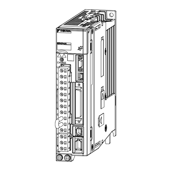
Part Names37
-
Functions44
-
-
Holding Brake148
-
Speed Control185
-
Position Control196
-
Torque Control206
-
-
-
Software Reset260
-
Preparations260
-
Applicable Tools260
-
-
-
Preparations262
-
Applicable Tools263
-
-
-
Program Jogging289
-
Origin Search294
-
Tuning300
-
-
-
Tuning Functions304
-
Diagnostic Tool305
-
-
-
Outline314
-
Restrictions314
-
Applicable Tools315
-
-
Custom Tuning341
-
-
Outline350
-
Preparations350
-
Applicable Tools351
-
-
-
Outline354
-
Preparations355
-
Applicable Tools355
-
-
Manual Tuning366
-
Diagnostic Tools382
-
Easy FFT384
-
Monitoring388
-
-
Loop Control407
-
Pitches408
-
Sequence409
-
Safety Functions413
-
-
Risk Assessment414
-
Stopping Methods418
-
-
-
-
Procedure421
-
-
-
Maintenance424
-
-
Alarm Displays428
-
Warning Displays468
-
Panel Operator486
-
-
-
Jog (Fn002)496
-
Easy FFT (Fn206)512
-
Parameter Lists515
-
-
Appendices554
-
-
Advertisement
Advertisement