Sign In
Upload
Manuals
Brands
YASKAWA Manuals
Controller
CIMR-AA Series
YASKAWA CIMR-AA Series Manuals
Manuals and User Guides for YASKAWA CIMR-AA Series. We have
1
YASKAWA CIMR-AA Series manual available for free PDF download: Quick Start Manual
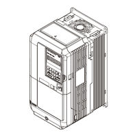
YASKAWA CIMR-AA Series Quick Start Manual (157 pages)
High Performance Vector Control Drive
Brand:
YASKAWA
| Category:
Controller
| Size: 19 MB
Table of Contents
This Page Intentionally Blank
3
Quick Reference
4
Table of Contents
6
Preface & General Safety
8
Preface
8
General Safety
8
Electrical Shock Hazard
9
Fire Hazard
10
Crush Hazard
10
Risk of Electric Shock
11
Hot Surfaces
11
Warranty Period
12
Receiving
13
Model Number and Nameplate Check
13
Three-Phase
14
Mechanical Installation
15
Installation Environment
15
Installation Orientation and Spacing
15
Single Drive Installation
16
Multiple Drive Installation (Side-By-Side Installation)
16
Electrical Installation
21
Standard Connection Diagram
21
Main Circuit Connection Diagram
23
Terminal Cover
24
Digital Operator and
26
Digital Operator and Front Cover
26
Removing the Digital Operator
26
Removing/Reattaching the Front Cover
27
Reattaching the Front Cover
27
Protective Cover
27
Main Circuit Wiring
28
Wire Gauges and Tightening Torque
28
Three-Phase 200 V Class
29
Three-Phase 400 V Class
30
Main Circuit Terminal and Motor Wiring
31
Ground Wiring
32
Control Circuit Terminal Block Functions
33
Input Terminals
33
Output Terminals
34
Serial Communication Terminals
34
Control I/O Connections
38
Terminal A2 Analog Input Signal Selection
40
Connect to a PC
41
Wiring Checklist
42
Start-Up Programming & Operation
43
Using the Digital Operator
43
Keys and Displays
43
The Drive and Programming Modes
45
Setup Group Parameters
46
Using the LO/RE Key on the Digital Operator
47
Start-Up Flowcharts
47
Flowchart A: Basic Start-Up and Motor Tuning
48
Subchart A-1: Simple Motor Setup Using V/F Control
49
Subchart A-3: Operation with Permanent Magnet Motors
51
Powering up the Drive
52
Application Selection
52
Basic Drive Setup Adjustments
52
Notes on Parameter Initialization
54
Voltage Input
54
Current Input
55
Switching between Main/Auxiliary Frequency References
55
Setting 2: Memobus/Modbus Communications
55
OLV/PM and AOLV/PM (A1-02 = 5, 6)
58
Setting 0: Disabled
59
Switching Acceleration Times by Digital Input
59
Switching Acceleration and Deceleration Times by Motor Selection
60
Switching Accel/Decel Times by a Frequency Level
60
E1-01 Related Values
63
V/F Pattern Settings (E1-03)
63
Setting a Predefined V/F Pattern (Setting 0 to E)
64
Setting Examples
71
H4-02, H4-03: Multi-Function Analog Output Terminal FM Gain and Bias H4-05, H4-06: Multi-Function Analog Output Terminal am Gain and Bias
73
Using Gain and Bias to Adjust Output Signal Level
73
H4-07, H4-08: Multi-Function Analog Output Terminal FM, am Signal Level Selection
74
Setting 2: Intelligent Stall Prevention
75
Setting 1: General-Purpose Stall Prevention
76
L3-05: Stall Prevention Selection During Run
77
Auto-Tuning
78
Types of Auto-Tuning
78
Auto-Tuning for Induction Motors
78
Auto-Tuning for Permanent Magnet Motors
79
Inertia Tuning and Speed Control Loop Auto-Tuning
80
Load Operation Test Run
82
Test Run with Load Connected
83
Test Run with the Load Connected
83
Test Run Checklist
83
Troubleshooting
85
Drive Alarms, Faults, and Errors
85
Fault Detection
85
Alarm Detection
92
Operator Programming Errors
94
Auto-Tuning Fault Detection
95
Copy Function Related Displays
98
Fault Reset Methods
99
Periodic Inspection & Maintenance
100
Inspection
100
Recommended Daily Inspection
100
Periodic Maintenance
102
Related Drive Parameters
103
Remove the Terminal Cover
103
Installing the Drive
104
Specifications
105
Heavy Duty and Normal Duty Ratings
105
Three-Phase 200 V Class Drives
105
Three-Phase 400 V Class Drives
106
Drive Specifications
106
Specification
107
Parameter List
108
Parameter Table
108
A1: Initialization Parameters
108
A2: User Parameters
108
B1: Operation Mode Selection
109
B2: DC Injection Braking and Short Circuit Braking
109
B3: Speed Search
110
B4: Timer Function
110
B5: PID Control
110
C2: S-Curve Characteristics
113
C3: Slip Compensation
113
C4: Torque Compensation
114
C5: Automatic Speed Regulator (ASR)
114
C6: Carrier Frequency
115
D1: Frequency Reference
115
D2: Frequency Upper/Lower Limits
116
D3: Jump Frequency
116
D4: Frequency Reference Hold and Up/Down 2 Function
116
D5: Torque Control
117
D6: Field Weakening and Field Forcing
117
D7: Offset Frequency
117
E: Motor Parameters
118
E2: Motor 1 Parameters
118
E5: PM Motor Settings
120
F2: Analog Input Card (AI-A3)
122
F3: Digital Input Card (DI-A3)
122
F4: Analog Monitor Card (AO-A3)
122
F5: Digital Output Card (DO-A3)
123
F6: Communication Option Card
123
H1: Multi-Function Digital Inputs
125
H2: Multi-Function Digital Outputs
127
H3: Multi-Function Analog Inputs
128
H4: Analog Outputs
129
H5: Memobus/Modbus Serial Communication
130
H6: Pulse Train Input/Output
130
L: Protection Function
131
L1: Motor Protection
131
L2: Momentary Power Loss Ride-Thru
131
L3: Stall Prevention
132
L4: Speed Detection
133
L5: Fault Restart
133
L6: Torque Detection
133
L7: Torque Limit
134
L8: Drive Protection
134
N1: Hunting Prevention
135
N: Advanced Performance Set-Up
135
O: Operator Related Parameters
137
O1: Digital Operator Display Selection
137
O2: Digital Operator Keypad Functions
137
O3: Copy Function
138
O4: Maintenance Monitor Settings
138
T1: Induction Motor Auto-Tuning
138
T2: PM Motor Auto-Tuning
139
T3: ASR and Inertia Tuning
140
U1: Operation Status Monitors
140
Analog Output Level
141
U2: Fault Trace
142
U3: Fault History
142
U4: Maintenance Monitors
143
U5: PID Monitors
144
U6: Operation Status Monitors
144
U8: Driveworksez Monitors
144
C Standards Compliance
145
Standards Compliance
145
European Standards
145
Guarding against Harmful Materials
146
EMC Guidelines Compliance
146
EMC Filter Installation
146
EMC Filters
148
UL Standards
149
Installation Area
149
Drive Short-Circuit Rating
151
Drive Motor Overload Protection
151
L1-01 Motor Overload Protection Selection
151
L1-02 Motor Overload Protection Time
152
Safe Disable Input Function
152
Safe Disable Circuit
153
Disabling and Enabling the Drive Output ("Safe Torque Off")
154
Revision History
155
Advertisement
Advertisement
Related Products
YASKAWA CIMR-AC2B0169
YASKAWA CIMR-AC4B0004
YASKAWA CIMR-AC4B0088
YASKAWA CIMR-AC4B0165
YASKAWA CIMR-AC Series
YASKAWA CIMR-A2A0030
YASKAWA CIMR-A2A0069
YASKAWA CIMR-A2A0250
YASKAWA CIMR-A4A0007
YASKAWA CIMR-A4A0018
YASKAWA Categories
Controller
DC Drives
Servo Drives
Robotics
Control Unit
More YASKAWA Manuals
Login
Sign In
OR
Sign in with Facebook
Sign in with Google
Upload manual
Upload from disk
Upload from URL