Sign In
Upload
Manuals
Brands
Xantrex Manuals
Inverter
MS2000
Xantrex MS2000 Manuals
Manuals and User Guides for Xantrex MS2000. We have
2
Xantrex MS2000 manuals available for free PDF download: Operation Manual, Installation Manual
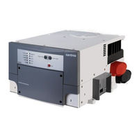
Xantrex MS2000 Operation Manual (126 pages)
Xantrex Sine Wave Inverter/Charger Operation Guide MS2000
Brand:
Xantrex
| Category:
Inverter
| Size: 1.16 MB
Table of Contents
About this Guide
5
Conventions Used
6
Symbols Used
6
Contact Information
7
Important Safety Instructions
9
Explosive Gas Precautions
11
Table of Contents
13
1 Introduction
19
About the MS2000 Sine Wave Inverter/Charger
20
Premium Power and Ease of Use
20
How MS2000 Works
21
Inverting
21
Charging
21
Xanbus System
23
Xanbus Enabled
23
Figure 1-1 Typical Xanbus System Diagram
23
Comprehensive Electronic Protection
24
MS2000 Features
25
Front Panel Features
25
Figure 1-2 Front Panel of the MS2000
25
Figure 1-3 Front Panel Lights and Buttons
26
Side Panel Features
27
Figure 1-4 Completed Connections on Side Panel
27
Figure 1-5 DC Grounding Completed
28
DC Terminal Covers and Battery Temperature Sensor
29
DC Terminal Covers
29
Battery Temperature Sensor
29
Figure 1-6 Battery Terminal Covers
29
Figure 1-7 Battery Temperature Sensor
29
System Accessories and Network Components
30
2 Operation
31
Operating the MS2000 with the System Control Panel
32
Using the System Control Panel
33
Figure 2-1 System Control Panel
33
On Start up
34
Power on Reset
34
System Start-Up Check
35
System Modes
36
Figure 2-2 System Control Panel
36
Figure 2-3 Operate Mode
37
Operate Mode
37
Power Save Mode
37
Safe Mode
38
Figure 2-4 Power Save Mode
38
Figure 2-5 Select Device Menu
39
Figure 2-6 System Settings Menu
39
Putting the System into Safe Mode
39
Figure 2-7 Safe Mode
40
Hibernate Mode
40
Operating in Invert Mode
42
Load Sense Mode
42
Operating Limits for Inverter Operation
43
Power Output
43
Operating in Charger Mode
44
Echo Charger Operation
45
Enabling and Disabling Operation from the System Control Panel
45
Figure 2-8 Select Device Menu
45
Figure 2-9 Echo Charger
46
Figure 2-10 Echo Charger Enabled
46
Charger Operation with Battery Temperature Sensor
47
Figure 2-11 Battery Temperature Sensor
47
Operating in Equalization Mode
48
Equalizing Batteries
49
Figure 2-12 Equalize on
49
Figure 2-13 Equalize Confirmation Warning
50
Figure 2-14 Equalization Home Screen
50
Figure 2-15 Equalize Cancellation Warning
51
Terminating the Equalization Process
52
Operating Limits for Charger Operation
52
Power Share
52
Monitoring the MS2000 Indicator Lights
53
Faults and Warnings
54
Monitoring Status Messages on the System Control Panel
54
3 Configuration
55
General Configuration Information
56
System Control
56
System Menu Map
57
Figure 3-1 System Menu Map
57
Figure 3-2 MS2000 Float System Screen (Example)
58
Figure 3-3 Select Device Menu
58
Viewing the Select Device Menu
58
Viewing the System Screen
58
Figure 3-4 MS2000 Basic Menu in Invert Mode
59
Selecting and Adjusting the Configurable Settings
59
Selecting the MS2000 Basic Menu
59
MS2000 Configuration Menus
60
Figure 3-5 MS2000 Menu
60
Figure 3-6 MS2000 Menu Structure - Overview
61
MS2000 Device Menu
62
Mode
62
Figure 3-7 Invert Mode - Basic Menu
62
Battery
63
AC Input
63
AC out
63
Echo Chg out
63
MS2000 Menu (Basic)
64
Inverter
64
Charger
65
Power Share
66
Equalize
66
Figure 3-8 Equalize on
67
Figure 3-9 Equalize Confirmation Warning
67
Figure 3-10 Equalization System Home Screen
67
Figure 3-11 Equalize Cancellation Warning
68
Batt Type
69
Batt Size
69
Clear Faults
70
MS2000 Menu (Advanced)
71
Inverter
71
Charger
71
Power Share
71
Configure Inv/Chg (Configure Inverter/Charger)
71
Max Chg Rate
72
Echo Chg
72
Load Sense
73
Equalize
73
Clear Faults
73
View Device Info
73
Basic Menu
73
Selecting the MS2000 Advanced Menu
74
Figure 3-12 Highlighting System on the Select Device Menu
74
Figure 3-13 Highlighting Global Menus
74
Returning to MS2000 Basic Menu
75
Sub-Menus
76
Configure Inv/Chg Menu (Configure Inverter/Charger Menu)
76
Lo DC Volt
76
Batt Type
76
Batt Size
76
Sense below
76
Sense Interval
77
Cfg AC Limits (Configure AC Limits)
77
Chg Stages
77
Eqz Volts
78
Force Charge
78
Cfg AC Limits (Configure AC Limits)
79
Lo AC Volt
79
Lo AC Freq
79
Hi AC Volt
80
Hi AC Freq
80
View Device Info Menu (Device Information Menu)
81
View Fault Log
81
View Warning Log
81
View Event Log
81
Restore Defaults
82
Figure 3-14 Restore Defaults Warning
82
4 Troubleshooting
83
Faults and Warnings
84
Fault Types
84
Warning Types
85
Troubleshooting Reference
86
General Troubleshooting Guidelines
87
Warning Messages
88
Fault Messages
91
Inverter Applications
97
Resistive Loads
97
Motor Loads
97
Problem Loads
97
Very Small Loads
97
Fluorescent Lights & Power Supplies
97
Clocks
98
Searching
98
Specifications
99
Inverter Specifications
100
Main Charger Specifications
101
Echo Charger Specifications
102
Transfer and General Specifications
102
Environmental Specifications
103
Physical Specifications with Projections
103
Regulatory Approvals
103
Fan Operation
103
Invert Power Derating Vs Ambient Temperature
104
Charger Mode
104
Figure A-1 Inverter Output Power Vs Ambient Temperature
104
B Battery Charging Reference for the Main Charger
105
Charging Algorithms (Formulas
106
Battery Type
106
Charge Algorithm Stages
106
Three-Stage Charging
106
Bulk Charge
107
Absorption Charge
107
Float Charge
107
Equalization Charge
108
Two-Stage Charging
108
Charge Algorithm Graph
109
Charge Algorithm Definitions
109
AC Reconnect Summary
110
100 C Terminology
112
Glossary
112
Abbreviations
115
Warranty and Product Information
117
Warranty
117
Return Procedure
119
Out of Warranty Service
119
Information about Your System
120
Index
121
Advertisement
Xantrex MS2000 Installation Manual (76 pages)
Xanbus-enabled Sine Wave Inverter/Charger
Brand:
Xantrex
| Category:
Inverter
| Size: 0.71 MB
Table of Contents
About this Guide
5
Conventions Used
6
Symbols Used
6
Contact Information
7
Important Safety Instructions
9
Explosive Gas Precautions
11
Personal Precautions When Working with Batteries
11
FCC Information to the User
12
Table of Contents
13
Installation Information
20
Before You Begin the Installation
20
Installation Codes
20
About the Xanbus System
21
Figure 1 Typical Xanbus System Diagram
21
System Accessories
22
Xanbus Enabled
22
Planning the Installation
23
Mounting Location of the MS2000
23
Size and Length of DC Cables
23
Two Key Performance Factors
23
AC, DC, and Network Components
24
Figure 2 Typical Marine Electrical System
25
AC Components
26
AC Input
26
Disconnect and Over-Current Protection Device
26
AC Output Neutral Bonding
27
AC Wiring
27
Distribution Panels
27
Batteries
29
DC Cabling
29
DC Components
29
DC Disconnects and Over-Current Devices
29
DC Grounding
30
Figure 3 MS2000 Hardware Materials as Shipped
31
Materials List
31
Unpacking and Inspecting the Inverter/Charger
31
Installation Tools and Materials
32
Installing the Inverter/Charger
33
Overview
33
Step 1: Choosing a Location for the Inverter/Charger
34
Considerations
36
Step 2: Mounting the Inverter/Charger
36
Figure 4 Approved Mounting Orientations
37
Figure 5 Front Panel with Wiring Compartment
38
General AC Wiring Considerations
38
Step 3: Connecting the AC Input and AC Output Wires
38
Connecting AC Input Wires
39
Connecting the AC Output Wires
40
Figure 6 AC in and AC Out: Hardwiring Completed
40
Step 4: Connecting the Main DC Cables
41
DC Connection Precaution
41
Preparing the Cables
41
Recommended Cable Sizes and Lengths and Fuse Size
41
Guidelines for Routing the DC Cables
42
Connecting the DC Cables to the Inverter/Charger
43
Figure 7 DC Cable Connections
44
Figure 8 DC Terminal Covers
44
Figure 9 Completed DC Wiring
45
DC Grounding
46
Figure 10 Completed DC Grounding
46
Step 5: Connecting the Echo Charger
47
DC Connection Precaution
47
Figure 11 Echo Charger Port
47
Preparing the Cable
47
Figure 12 Inserting Cable into the Echo Charger Connector
48
Connecting the Cable
49
Step 6: Connecting the Battery Temperature Sensor (BTS)
49
Figure 13 BTS with Cable
49
Figure 14 BTS Mounted on the Negative Battery Terminal
50
Mounting Options
50
Mounting to the Negative Battery Terminal
50
Figure 15 Connecting the BTS Cable to Battery Temp. Jack
51
Figure 16 BTS Mounted on the Battery Case
52
Mounting to the Side of the Battery Case
52
Figure 17 Connecting to a Network Jack
53
Step 7: Connecting to the Network
53
Step 8: Performing Checks Prior to Initial Start-Up
54
Step 9: Testing Your Installation
55
Testing in Charge Mode
55
Testing in Invert Mode
55
Testing in AC Bypass Mode
56
Testing the Echo Charger
56
Installation
20
Inverter/Charger Physical Specifications
56
Figure 18 Inverter/Charger Dimensions
57
Battery Information
58
Terminology
58
Battery Types
59
Starting Batteries
59
Deep Cycle Batteries
59
Sealed Gel-Cell
60
Environment
60
Location
60
Enclosures
61
Temperature
61
Battery Bank Sizing
62
Estimating Battery Requirements
63
Battery Bank Sizing Example
64
Battery Bank Sizing Worksheet
65
Monthly Battery Maintenance
66
Preparation for Cleaning Batteries
67
Clothing
67
Equipment
67
Supplies
67
Tools
67
Maintaining and Cleaning
68
Battery Enclosure and Batteries
68
Terminals & Lugs
68
Battery Cables
69
Cabling & Hook-Up Configurations
70
Figure 19 Batteries Connected in Parallel
70
Parallel Connection
70
Figure 20 Batteries Connected in Series
71
Series Connection
71
Figure 21 Batteries in Series-Parallel Connections
72
Series-Parallel Connections
72
Index
73
Advertisement
Related Products
Xantrex Marine Instruments
Xantrex Meter Display
Xantrex Internal M9B-HFS Series
Xantrex 120 VAC/60
Xantrex 1200, 1750
Xantrex 230 VAC/50
Xantrex 6000 Series
Xantrex 784-0330
Xantrex 784-9115-01
Xantrex 784-9115S-01
Xantrex Categories
Inverter
Power Supply
Battery Charger
Power Pack
Controller
More Xantrex Manuals
Login
Sign In
OR
Sign in with Facebook
Sign in with Google
Upload manual
Upload from disk
Upload from URL