Sign In
Upload
Manuals
Brands
Woodward Manuals
Controller
ProAct Digital Plus
User Manuals: Woodward ProAct Digital Plus Actuator
Manuals and User Guides for Woodward ProAct Digital Plus Actuator. We have
1
Woodward ProAct Digital Plus Actuator manual available for free PDF download: Installation And Operation Manual
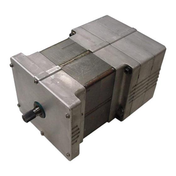
Woodward ProAct Digital Plus Installation And Operation Manual (120 pages)
Electric Actuator with Integral Driver
Brand:
Woodward
| Category:
Controller
| Size: 2 MB
Table of Contents
Table of Contents
3
Warnings and Notices
6
Electrostatic Discharge Awareness
7
Regulatory Compliance
8
Chapter 1. General Information
11
Introduction
11
How to Use this Manual
11
Description
11
Figure 1-1A. Proact Digital Plus Functional Overview
12
Figure 1-1B. Proact Digital Plus Functional Overview
13
Controller Overview
14
Mechanical Setup
14
Figure 1-2. Driver Overview
15
Chapter 2. Hardware Installation
19
Unpacking
19
Mounting Location
19
Actuator Application Guidelines
20
Mounting
20
Actuator Selection and Temperature Monitoring Guidelines
20
Figure 2-1. Temperature Monitoring Zone (Model III Shown)
21
Figure 2-2. Base Mount Actuator Selection Guidelines
21
Figure 2-3. Flange Mount Actuator Selection Guidelines
22
Fuel Position Stops
23
Linkage
23
Figure 2-4. Fuel Stops
23
Figure 2-5A. Proact Digital Plus Actuator Outline Drawing
25
Figure 2-5B. Proact Digital Plus Actuator Outline Drawing
26
Figure 2-5C. Proact Digital Plus Actuator Outline Drawing
27
Figure 2-5D. Proact Digital Plus Actuator Outline Drawing
28
Chapter 3. Wiring
29
Electrical Connections
29
Figure 3-1A. Control Wiring Diagram (Blank Cover)
30
Figure 3-1B. Control Wiring Diagram (CAN Only)
31
Figure 3-1C. Control Wiring Diagram (Digital Plus)
32
Figure 3-1D. Control Wiring Diagram (CAN Only with External Run Enable)
33
Figure 3-2. Representative I/O Schematic
34
Figure 3-3. Correct Wiring to Power Supply
36
Figure 3-4. Incorrect Power Supply Wiring
36
Proact Inputs/Outputs
37
Communication Hardware Descriptions
39
Chapter 4. Setup, Calibration, and Adjustments
41
General Description
41
Setup
41
Calibration
42
Adjustments
42
Chapter 5. Description of Operation
43
Position Control
43
Position Demand
43
Figure 5-1. Controller Overview
43
Multiple Demands
44
Driver Output and Position Feedback
44
Figure 5-2. Primary/Backup Position Demand State Machine
44
Drive Current Limitations
45
Current Limiting Based on Temperature
45
Communications
46
CAN Communications
46
Figure 5-3. Current Limits
46
Service Port (RS-232) Communications
47
Service Tool
47
Figure 5-4. Operating Modes
47
User Operating Modes
48
Figure 5-5. Typical Service Tool Screen
49
Chapter 6. Diagnostics
50
General Information
50
Power-Up Diagnostics
51
Figure 6-1. Typical Flash Code
53
Chapter 7. CAN Details
60
Overview
60
CAN Bit Timing
60
Source Address/Harness Code Strategy
60
Configuration Strategy
60
CAN Extensions
60
Diagnostics from Proact Actuator
63
Diagnostics/Events
63
Event Codes
64
Transmission Rate
65
Arbitration
66
Figure 7-1. Typical Arbitration Field Example
66
Chapter 8. Service Tool
67
Description
67
Figure 8-1. Operating Modes
68
Getting Started
70
Watch Window Numeric Format
73
Using Watch Window
73
Software Version Identification
75
Watch Window Standard and Professional
75
Chapter 9. Proact™ Parameter Setup
76
Configure Mode
76
Configure Mode Parameters
78
Figure 9-1. Configure Mode
78
Figure 9-2. Configure Mode: Unit Setup
79
Figure 9-3. Configure Mode: Demand Setup
81
Adjusting User Stops and Dynamics
82
Figure 9-4. Min/Max Stops Relative to the Overall Travel
83
Figure 9-5. Electrical Stop Adjustments Relative to the Mechanical Min and Max Stops
84
Figure 9-6. Service Mode: Adjust User Stops
85
Adjusting and Testing Actuator Dynamics
86
Figure 9-7. Auto Stroke Mode Flowchart
87
Figure 9-8. Manual Stroke Mode Flowchart
88
Service Mode Parameters
89
Figure 9-9. Service Mode: Hardware Adjustments
90
Monitoring Application Parameters
93
Figure 9-10. Service Mode: Unit Status
93
Figure 9-11. Service Mode: Position Control
95
Figure 9-12. Service Mode: Status Error Alarms
96
Figure 9-13. Service Mode: Status Error Shutdowns
97
Figure 9-14. Service Mode: Status Error Log (1)
97
Figure 9-15. Service Mode: Status Error Log (2)
98
Figure 9-16. Service Mode: Temperature Histogram
99
Chapter 10. Troubleshooting
100
Introduction
100
Troubleshooting Procedure
100
General System Troubleshooting Guide
101
Mechanical Troubleshooting Guide
101
Electrical Troubleshooting Guide
102
Performance Troubleshooting Guide
104
Chapter 11. Proact™ Digital Plus Specifications
106
Environmental Specifications
106
Hardware Specifications
106
Electrical Specifications
107
I/O Specifications
107
Software
109
Figure 11-1. Transfer Function
110
Chapter 12. Product Support and Service Options
111
Product Support Options
111
Product Service Options
111
Returning Equipment for Repair
112
Replacement Parts
112
Engineering Services
113
Contacting Woodward's Support Organization
113
Technical Assistance
114
Appendix . Pro Act ™ Program Summary
115
Configure Mode Settings
115
Service Mode Settings
115
Service Tool Passwords
116
Summary of Alarms and Shutdowns
116
Revision History
117
Declarations
118
Advertisement
Advertisement
Related Products
Woodward ProAct P Series FL
Woodward ProAct III
Woodward ProAct IV
Woodward ProAct ITB
Woodward ProTech-GII
Woodward PGM-EG 500
Woodward PCM1x
Woodward PG Dial Governor
Woodward PCM1-G
Woodward PCL1
Woodward Categories
Controller
Control Unit
Relays
Control Systems
Industrial Equipment
More Woodward Manuals
Login
Sign In
OR
Sign in with Facebook
Sign in with Google
Upload manual
Upload from disk
Upload from URL