Sign In
Upload
Manuals
Brands
Woodward Manuals
Control Unit
MicroNet 5437-1107
Woodward MicroNet 5437-1107 Manuals
Manuals and User Guides for Woodward MicroNet 5437-1107. We have
1
Woodward MicroNet 5437-1107 manual available for free PDF download: Product Manual
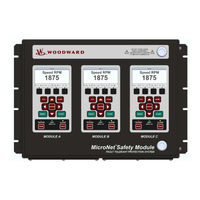
Woodward MicroNet 5437-1107 Product Manual (112 pages)
Safety Module Fault Tolerant Protection System
Brand:
Woodward
| Category:
Control Unit
| Size: 7 MB
Table of Contents
Table of Contents
3
Warnings and Notices
7
Electrostatic Discharge Awareness
8
Regulatory Compliance
9
Acronyms and Definitions
11
Chapter 1. General Information
12
Description
12
Applications
13
Figure 1-1. Typical Micronet Safety Module Application (Voted Trip Relay Models)
13
Figure 1-2. Typical Micronet Safety Module Application (Independent Trip Relay Models)
14
Figure 1-3. Typical Gas Turbine Application (Voted Trip Relay Models)
14
Figure 1-4. Typical Safety PLC Application (Voted Trip Relay Models)
15
Chapter 2. Installation
16
Introduction
16
Unpacking
16
System Installation Procedure
16
Enclosures
17
Figure 2-1. Typical Micronet Safety Module Bulkhead Package-Front View
17
Figure 2-2. Typical Micronet Safety Module Bulkhead Package-Front Door Open
18
Figure 2-2A. Bulkhead Schematic Showing Front Panel a Connection to Module a and Front Panel C Connection to Module C-Top View
18
Figure 2-3. Mounting Outline Diagram for Bulkhead-Mounted Models
19
Module Removal and Installation - Bulkhead Mount Package
20
Figure 2-4A. Typical Micronet Safety Module Panel Mount Package-Front View
21
Figure 2-4B. Typical Micronet Safety Module Panel Mount Package-Rear View with Cover
21
Figure 2-4C. Typical Micronet Safety Module Panel Mount Package-Rear View Without Cover
22
Figure 2-4D. Panel Mount Schematic Showing Front Panel a Connection to Module a and Front Panel C Connection to Module C-Top View
22
Figure 2-5A. Mounting Outline Diagram for Panel-Mount Models
23
Figure 2-5B. Mounting Outline Diagram for Panel-Mount Models
24
Module Removal and Installation - Panel Mount Package
25
Figure 2-5C. Panel Cutout Diagram for Panel-Mount Models
25
Mounting Location Considerations
27
Environmental Specifications
28
Power Supply Requirements
28
Shielded Wiring
29
Control Wiring Guidelines
29
Figure 2-6. Screw Connection Terminal Block
30
Figure 2-7. Inside View of Micronet Safety Module
32
Figure 2-8. Micronet Safety Module Control Wiring Diagram
33
Figure 2-9. Trip Module - Included Within Voted Trip Relay Units Only
34
Figure 2-10A. Power Supply Field Wiring Routing & Stress Relief Diagram
34
Figure 2-10B. Configurable I/O Wiring Routing & Stress Relief Diagram
35
Figure 2-10C. Relay Output Field Wiring Routing & Stress Relief Diagram
35
Figure 2-11A. Example MPU (Passive Magnetic Pickup Unit) Wiring
36
Figure 2-11B. Example Proximity Probe (Active Magnetic Pickup Unit) Wiring (Internal Power)
37
Figure 2-11C. Example Proximity Probe (Active Magnetic Pickup Unit) Wiring (External Power, Non-Preferred)
37
Figure 2-11D. Example Eddy Current Probe (Active Magnetic Pickup Unit) Wiring
37
Figure 2-12A. Example Standard Discrete Input Wiring (Internal Power Option)
38
Figure 2-12B. Example Standard Discrete Input Wiring (External Power Option)
38
Figure 2-13A. Example Configurable Input Wiring-Discrete Input (Internal Power Option)
39
Figure 2-13B. Example Configurable Input Wiring-Discrete Input (External Power Option)
40
Figure 2-14. Example Configurable Input Wiring-Analog Input
40
Figure 2-15. Example Analog Output Wiring
41
Figure 2-16A. Example Trip Relay Output Wiring
41
Figure 2-16B. Example Trip Relay Wiring (Per Module) (Independent Trip Relay) (Internal Supply)
42
Figure 2-16C. Example Trip Relay Wiring (Per Module) (Independent Trip Relay) (External Supply)
42
Figure 2-16D. Example Trip Relay Wiring (Voted Trip Relay Models)
43
Figure 2-16E. Example Programmable Relay Wiring (Internal Supply)
43
Figure 2-16F. Example Programmable Relay Wiring (External Supply)
44
Figure 2-17. Power Supply Relationship Diagram
45
Figure 2-18A. Serial Port Interface Diagram-RS-232
46
Figure 2-18B. Serial Com Port Interface Diagram -RS-485
46
Figure 2-19. Service Tool Cable/Interface Diagram
47
Chapter 3. Functionality
48
Features
48
Product Models
49
Figure 3-1. Basic Functional Overview of Independent Trip Relay Models
50
Figure 3-2. Functional Diagram of Single Micronet Safety Module with Independent Trip Relay Outputs
51
Figure 3-3. Example TMR Trip Block Assembly Interface
52
Figure 3-4. Basic Functional Overview of Voted Trip Relay Models
53
Figure 3-5. Functional Diagram of Single Micronet Safety Module with Voted Trip Relay Outputs
53
Figure 3-6. Simplex Trip Block Assembly
54
Figure 3-7. Dual Redundant Trip Block Assembly
54
Inputs and Outputs
56
Figure 3-8. Discrete Input Example
58
Figure 3-9. Analog Input Example
59
Figure 3-10. Programmable Relay Output Diagram
60
Overspeed and Over-Acceleration Detection and Trip
61
Start Logic
62
Figure 3-11. Over-Acceleration Enabling Diagram
62
Configurable Logic
63
Test Routines
64
Alarm, Trip, and Event Latches
67
System Logs
68
Response Time Performance
70
Chapter 4. Modbus Communications
72
Modbus Communications
72
Monitor Only
72
Monitor and Control
72
Modbus Communication
73
Port Adjustments
73
Micronet Safety Module Parameter Addresses
73
Chapter 5. Troubleshooting
79
I/O Troubleshooting
80
Trip Indications
83
Alarm Indications
85
Configuration Guidance
87
Chapter 6. Safety Management
90
Product Variations Certified
90
Safe State
90
SIL Specifications
90
Failure Rate Data
91
Response Time Data
91
Limitations
92
Management of Functional Safety
92
Restrictions
92
Competence of Personnel
93
Operation and Maintenance Practice
93
Installation and Site Acceptance Testing
93
Functional Testing after Initial Installation
93
Functional Testing after Changes
93
Proof Testing (Functional Test)
93
Chapter 7. Asset Management
95
Product Storage Recommendations
95
Refurbishment Period Recommendation
95
Chapter 8. Product Support and Service Options
96
Product Support Options
96
Product Service Options
96
Returning Equipment for Repair
97
Replacement Parts
98
Engineering Services
98
Contacting Woodward's Support Organization
98
Technical Assistance
99
Appendix . Modbus Ethernet Gateway Information
100
Introduction
100
B&B Electronics Setup
100
Lantronix Setup
105
Revision History
110
Declarations
111
Advertisement
Advertisement
Related Products
Woodward MicroNet 5437-1104
Woodward MicroNet 5437-1105
Woodward MicroNet 5437-1106
Woodward TecJet 50
Woodward 505XT
Woodward 5448-882
Woodward 5448-880
Woodward 5448-881
Woodward TecJet 52 Gen II
woodward MicroNet TMR
Woodward Categories
Controller
Control Unit
Relays
Control Systems
Industrial Equipment
More Woodward Manuals
Login
Sign In
OR
Sign in with Facebook
Sign in with Google
Upload manual
Upload from disk
Upload from URL