Sign In
Upload
Manuals
Brands
Woodward Manuals
Relays
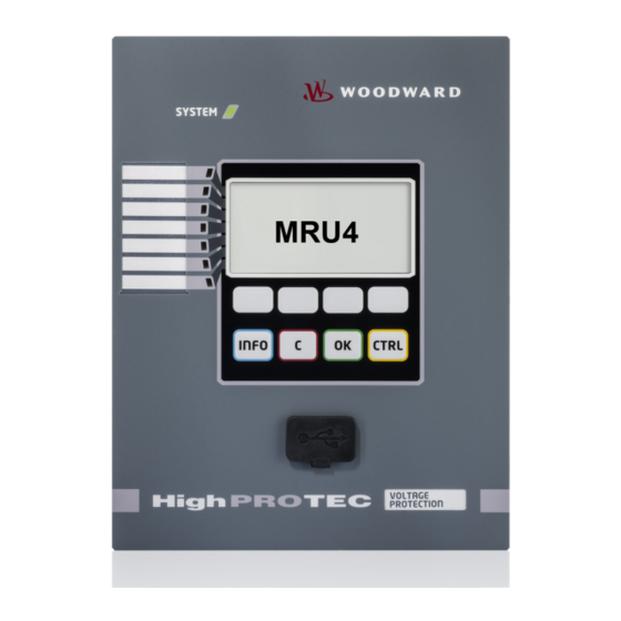
High PROTEC MRU4
Woodward High PROTEC MRU4 Manuals
Manuals and User Guides for Woodward High PROTEC MRU4. We have
1
Woodward High PROTEC MRU4 manual available for free PDF download: Manual
Woodward High PROTEC MRU4 Manual (656 pages)
Brand:
Woodward
| Category:
Relays
| Size: 8 MB
Table of Contents
MRU4 Functional Overview
2
Voltage and Frequency Supervision
3
Order Code
3
Table of Contents
4
Comments on the Manual
9
Information Concerning Liability and Warranty
9
Important Definitions
10
Proper Use
11
Electrostatic Discharge Awareness
13
Scope of Delivery
14
Storage
15
Important Information
15
Symbols
16
General Conventions
18
Access Level
22
Load Reference Arrow System
23
Device Planning
24
Device Planning Parameters of the Device
25
Three-Side-View - 19"
27
Installation and Connection
27
Three-Side-View - 8-Pushbutton Version
28
Installation Diagram 8-Pushbutton Version
29
Assembly Groups
30
Grounding
30
Legend for Wiring Diagrams
31
Slot X1: Power Supply Card with Digital Inputs
33
DI8-X Power Supply and Digital Inputs
34
Terminals
36
Electro-Mechanical Assignment
36
Slot X2: Relay Output Card
37
Binary Output Relays and System Contact
38
Slot X3: Voltage Transformer Measuring Inputs
40
Voltage Measuring Inputs
41
Voltage Transformers
43
Check of the Voltage Measuring Values
43
Wiring Examples of the Voltage Transformers
44
Three-Phase Voltage Measurement: "Star-Connection"
44
Measurement of the Residual Voltage VG Via Auxilliary Windings
45
Three-Phase Voltage Measurement: "Delta-Connection"
46
Fourth Measuring Input for Measuring a Synchronisation Voltage
47
Two-Phase Voltage Measurement: "Open Delta"
49
Slot X100: Ethernet Interface
50
Ethernet - RJ45
51
Slot X101: IRIG-B00X
52
Irig-B00X
53
Slot X103: Data Communication
54
Modbus RTU / IEC 60870-5-103 Via RS485
55
RS485 – Type 1
55
Electro-Mechanical Assignment Type 1
55
Type 1 Wiring Example, Device in the Middle of the BUS
56
Type 1 Wiring Example, Device at the End of the BUS
56
RS485 – Type 2
57
Electro-Mechanical Assignment Type 2
57
Type 2 Wiring Example, Device at the End of the BUS
58
Type 2 Wiring Example, Device in the Middle of the BUS
58
Type 2 Shielding Options (2-Wire + Shield)
59
Type 2 Shielding Options (3-Wire + Shield)
59
Profibus DP/ Modbus RTU / IEC 60870-5-103 Via Fibre Optic
60
Modbus RTU / IEC 60870-5-103 Via D-SUB
61
Profibus DP Via D-SUB
62
Ethernet / TCP/IP Via Fiber Optics
62
PC Interface - X120
63
Navigation - Operation
64
Leds
65
LED "System OK"
65
Display
65
Softkeys
65
INFO Key
66
(Signals/Messages)
66
C Key
66
CTRL Key
67
OK Key
67
RS232 Interface (Smart View Connection)
67
Basic Menu Control
68
Input, Output and LED Settings
69
Configuration of the Digital Inputs
69
Assigning a Digital Input Onto One or Mutliple Modules
70
Connecting a Module Input with a Digital Input
70
Checking the Assignments of a Digital Input
71
Device Parameters of the Digital Inputs on DI-8P X
72
Signals of the Digital Inputs on DI-8P X
74
Output Relays Settings
75
Binary Output Relays Acknowledgment Options
76
System Contact
78
Direct Commands of OR-5 X
79
Device Parameters of the Binary Output Relays on OR-5 X
81
Input States of the Binary Output Relays on OR-5 X
93
Signals of the Binary Output Relays on OR-5 X
97
Leds Group a
98
Global Protection Parameters of the LED Module
98
LED Module Input States
108
LED Configuration
112
Leds Can be Acknowledged by
113
The "System OK" LED
115
Smart View
116
Measurement Display
117
Measuring Values
117
Read out Measured Values
117
Energy Units
118
Temperature Unit
118
Cutoff Level
118
Voltage - Measured Values
119
Statistics
123
Configuration of the Minimum and Maximum Values
123
Configuration of the Current Based Average Value Calculation
124
Configuration of the Voltage Based Average Value Calculation
124
Configuration of the Power Based Average Value Calculation
125
Direct Commands
126
Global Protection Parameters of the Statistics Module
126
States of the Inputs of the Statistics Module
128
Signals of the Statistics Module
128
Counters of the Module Statistics
129
Voltage - Statistic Values
130
System Alarms
134
Demand Management
134
Configuring the Demand
135
Window Configuration = Sliding
136
Window Configuration = Fixed
136
Configuring the Peak Value Supervision
137
Min. and Max. Values.
137
Peak Values
137
THD Protection
138
Device Planning Parameters of the Demand Management
138
Signals of the Demand Management (States of the Outputs)
138
Global Protection Parameter of the Demand Management
139
States of the Inputs of the Demand Management
139
Collective Acknowledgments for Latched Signals
140
Options for Individual Acknowledgments for Latched Signals
141
Manual Acknowledgment
142
External Acknowledgments
142
Manual Resets
143
Reset to Factory Defaults
143
Status Display
144
Operating Panel (HMI)
145
Special Parameters of the Panel
145
Direct Commands of the Panel
145
Global Protection Parameters of the Panel
145
Disturbance Recorder
146
Example Disturbance Recorder Timing Chart I
148
Example Disturbance Recorder Timing Chart II
149
Deleting Disturbance Records
150
Read out Disturbance Records
150
Direct Commands of the Disturbance Recorder
151
Global Protection Parameters of the Disturbance Recorder
151
Disturbance Recorder Input States
153
Disturbance Recorder Signals
153
Special Parameters of the Disturbance Recorder
154
Fault Recorder
154
Definitions
155
Behaviour of the Fault Recorder
156
Modes
156
Memory
157
Content of a Fault Record
158
How to Set up the Fault Recorder
159
How to Navigate Within the Fault Recorder
159
How to Read out the Fault Recorder
159
Fault Recorder Signals
160
Global Protection Parameters of the Fault Recorder
160
Direct Commands of the Fault Recorder
160
Three Different Classes of Events
161
Event Recorder
161
Read out the Event Recorder
162
Direct Commands of the Event Recorder
162
Event Recorder Signals
162
Trend Recorder
162
Global Protection Parameters of the Trend Recorder
164
Direct Commands of the Trend Recorder
165
Genearal Values of the Trend Recorder
165
Trend Recorder Signals (Output States)
165
Global Values of the Trend Recorder
166
Device Planning Parameters of the Serial Scada Interface
167
Signals (Output States) of the SCADA Interface
167
Communication Protocols
167
TCP/IP Parameter
168
Modbus Protocol Configuration
169
Error Handling - Hardware Errors/Errors on Protocol Level
170
Modbus RTU
170
Hardware Connection
170
Configuration of the Devices
170
Modbus TCP
171
Setting the TCP/IP Parameters
171
Global Protection Parameters of the Modbus
172
States of the Module Inputs of the MODBUS Protocol
182
Values of the MODBUS Protocol
186
Counters of the MODBUS Protocol
188
Modbus Signals (Output States)
188
Modbus Values
189
Profibus
190
Direct Commands of the Profibus
191
Global Protection Parameters of the Profibus
191
Inputs of the Profibus
198
Profibus Signals (Output States)
201
Profibus Values
202
IEC60870-5-103 Protocol Configuration
204
Time Synchronization
205
Spontaneous Events
205
Cyclic Measurement
205
Disturbance Recording
205
Global Protection Parameters of the IEC60870-5-103
206
IEC60870-5-103 Signals (Output States)
207
IEC60870-5-103 Values
207
Iec61850
208
Generation/Export of a SCD File
209
Import of the .SCD File into the Device
209
IEC 61850 Virtual Outputs
209
Direct Commands of the IEC 61850
210
Global Parameters of the IEC 61850
210
States of the Inputs of the IEC 61850
214
IEC 61850 Module Signals (Output States)
216
IEC 61850 Module Values
219
Values of the IEC 61850
220
DNP Device Planning
221
DNP Protocol General Settings
221
Dnp3
221
Point Mapping
222
Application Example Setting a Relay
223
Direct Commands of the DNP
224
Global Protection Parameters of the DNP
224
Inputs of the DNP
251
Options of the DNP
259
Selectable Switchgears of the DNP
259
DNP Signals (Output States)
260
DNP Values
261
Time Zones
262
Time Synchronisation
262
Accuracy of Time Synchronisation
263
Without Time Synchronisation
264
Time Synchronisation with Local Time
264
Time Synchronisation with UTC Time
264
Selection of Timezone and Synchronisation Protocol
264
Global Protection Parameters of the Time Synchronization
265
Sntp
269
Accuracy
270
Using Two SNTP Servers
270
SNTP Commissioning
270
Fault Analysis
271
Global Protection Parameters of the SNTP
272
Direct Commands of the SNTP
272
Device Planning Parameters of the SNTP
272
Signals of the SNTP
274
SNTP Counters
274
SNTP Values
276
IRIG-B00X - Principle, General Use
277
IRIG-B Commissioning
278
IRIG-B Control Commands
278
Global Protection Parameters of the IRIG-B00X
279
Device Planning Parameters of the IRIG-B00X
279
Direct Commands of the IRIG-B00X
279
Signals of the IRIG-B00X (Output States)
280
IRIG-B00X Values
281
Device Parameters
282
Field Parameters
282
Protection Parameters
282
Parameter Definitions
282
Device Planning Parameters
283
State of the Module Inputs
283
Signals
283
Adaptive Parameter Sets
284
Adaptive Parameter Set Activation Signals
289
Passwords – Areas
301
Access Authorizations (Access Areas)
301
Access Areas (Password Level)
302
Available Levels/Access Authorizations
303
How to Find out What Access Areas/Levels Are Unlocked
303
Deactivating Passwords During Commissioning
304
Unlocking Access Areas
304
Changing Passwords
304
Password Entry at the Panel
305
Password Forgotten
305
Direct Authorization for an Access Area
306
Parameter Setting at the HMI
306
Context-Dependent Access Authorization
308
Setting Group Switch
310
Setting Groups
310
Signals that Can be Used for PSS
311
Bypass of the Setting Lock
319
Setting Lock
319
Device Parameters
320
Date and Time
320
Version
320
Display of ANSI-Codes
320
TCP/IP Settings
320
Direct Commands of the System Module
321
Global Protection Parameters of the System
322
System Module Input States
324
System Module Signals
325
Special Values of the System Module
326
Field Parameters - General
327
Field Parameters - Voltage Related
327
Permanent Blocking
329
Temporary Blocking
330
To Activate or Deactivate the Tripping Command of a Protection Module
331
Activate, Deactivate Respectively Block Temporarily Protection Functions
332
Module: Protection (Prot)
333
Blocking All Protective Elements Enduringly
333
Blocking All Protective Elements Temporarily
333
Blocking All Trip Commands Enduringly
334
Blocking All Trip Commands Temporarily
334
General Alarms and General Trips
336
Direct Commands of the Protection Module
341
Global Protection Parameters of the Protection Module
341
Protection Module Signals (Output States)
342
Wiring
343
Switchgear/Breaker - Manager
343
Single Line Diagram
343
Switchgear Configuration
343
Assignment of Position Indications
344
Single Position Indication Aux on or Aux off
346
Single Position Indication – Aux on
346
Setting of Supervision Times
347
Interlockings
347
Single Position Indication – Aux off
347
Trip Manager – Assignment of Commands
349
Ex ON/OFF
351
Synchronised Switching
351
Switching Authority
352
Non Interlocked Switching
353
Manual Manipulation of the Switchgear Position
353
Double Operation Locking
353
Switch Direction Control/Anti Pumping
353
Counters of the Command Execution Supervision
354
Slow Switchgear Alarm
354
Switchgear Wear
354
Switchgear Wear Curve
355
Breaker Maintenance Curve for a Typical 25Kv Breaker
355
Global Protection Parameters of the Breaker Wear Module
356
Breaker Wear Signals (Output States)
356
Breaker Wear Counter Values
356
Direct Commands of the Breaker Wear Module
356
Global Protection Parameters of the Control Module
357
Control Moduel Input States
357
Control Parameters
357
Synchronization Inputs
358
Signals of the Control Module
358
Assignable Trip Commands (Trip Manager)
367
Direct Commands of a Controlled Circuit Breaker
368
Global Protection Parameters of a Controlled Circuit Breaker
368
Controlled Circuit Breaker Input States
374
Signals of a Controlled Circuit Breaker
376
Control - Example: Switching of a Circuit Breaker
378
Protective Elements
381
Interconnection
381
V - Voltage Protection [27,59]
382
Device Planning Parameters of the Voltage Protection Module
385
Global Protection Parameters of the Voltage Protection Module
385
Setting Group Parameters of the Voltage Protection Module
386
Voltage Protection Module Input States
388
Voltage Protection Module Signals (Output States)
389
Commissioning: Overvoltage Protection [59]
390
Commissioning: Undervoltage Protection [27]
390
VG, VX - Voltage Supervision [27A, 27TN/59N, 59A]
391
27TN/59N - 100% Stator Ground Fault Protecton "VX Meas H3"
392
Global Protection Parameters of Residual Voltage Supervision Module
395
Device Planning Parameters of the Residual Voltage Supervision Module
395
Setting Group Parameters of the Residual Voltage Supervision Module
396
Residual Voltage Supervision Module Input States
397
Residual Voltage Supervision Module Signals (Output States)
397
Commissioning: Residual Voltage Protection - Measured [59N]
398
Commissioning: Residual Voltage Protection - Calculated [59N]
399
Frequency - Measuring Principle
400
F - Frequency [81O/U, 78, 81R]
400
Frequency Functions
401
Working Principle F and F
402
Working Principle Df/Dt
404
Df/Dt - Rate of Change of Frequency
404
Working Principle F and Df/Dt | F and Df/Dt
406
Working Principle F and DF/DT F and DF/DT
408
Voltage Vectors at Mains Parallel Operation
412
Equivalent Circuit at Synchronous Generator in Parallel with the Mains
412
Measuring Principle of Vector Surge Supervision
412
Equivalent Circuit at Mains Failure
413
Voltage Vectors at Mains Failure
413
Working Principle Delta Phi
414
Voltage Vector Surge
414
Device Planning Parameters of the Frequency Protection Module
416
Global Protection Parameters of the Frequency Protection Module
416
Setting Group Parameters of the Frequency Protection Module
417
Frequency Protection Module Input States
419
Frequency Protection Module Signals (Output States)
419
Commissioning: Overfrequency [F]
420
Commissioning: Underfrequency [F]
420
Commissioning: Df/Dt - Rate of Change of Frequency
421
Commissioning: F and DF/DT – Underfrequency and DF/DT
423
Commissioning: F and DF/DT – Overfrequency and DF/DT
423
Commissioning: Delta Phi - Vector Surge
424
V 012 – Voltage Asymmetry [47]
425
Device Planning Parameters of the Asymmetry Module
427
Global Protection Parameter of the Asymmetry-Module
427
Parameter Set Parameters of the Asymmetry Module
428
States of the Inputs of the Asymmetry Module
429
Signals of the Asymmetry Module (States of the Outputs)
430
Commissioning: Asymmetry Protection
430
Voltage Difference
431
Sync - Synchrocheck [25]
431
Frequency Difference (Slip Frequency)
432
Angular or Phase Difference
433
Synchronization Modes
435
Working Principle Synchrocheck (Generator-To-System)
435
Working Principle Synchrocheck (System-To-System)
437
Synchrocheck Override Conditions
439
Device Planning Parameters of the Synchrocheck Module
440
Global Protection Parameters of the Synchrocheck Module
440
Setting Group Parameters of the Synchrocheck Fault Module
441
Synchrocheck Module Input States
444
Signals of the Synchrocheck Module (Output States)
444
Values of the Syncrocheck
445
Signals that Trigger a Synchrocheck
446
Reconnection Module
455
Release Logic for the Generator Circuit Breaker
456
Voltage Release Via Remote Control Connection from the PCC
457
Voltage Release by (Self-) Measured Voltage Values
457
PCC in HV Systems
458
PCC in MV Systems
459
Device Planning Parameters of the Reconnection Module
460
Global Protection Parameters of the Reconnection Module
460
Decoupling Functions of the Reconnection Module
461
Setting Group Parameters of the Reconnection Module
474
Input States of the Reconnection Module
476
Reconnection Module Signals (Output States)
477
LVRT - Low Voltage Ride through [27(T)]
478
Functional Principle of the LVRT
479
Auto Reclosure Controlled LVRT
480
Device Planning Parameters of the Low-Voltage-Ride-Through
483
Setting Group Parameters of the Low-Voltage-Ride-Through
483
General Application Notes on Setting the LVRT
488
Special Application Notes on Setting the LVRT-Profile
488
Global Protection Parameters of the Low-Voltage-Ride-Through
489
Inputs of the Low-Voltage-Ride-Through
489
Signals (Output States) of the Low-Voltage-Ride-Through
490
Counter Values of the Low-Voltage-Ride-Through
490
Direct Commands of the Low-Voltage-Ride-Through
491
Intertripping (Remote)
492
Device Planning Parameters of the Intertripping Module
495
Global Protection Parameters of the Intertripping Module
495
Setting Group Parameters of the Intertripping Module
496
Intertripping Module Input States
497
Intertripping Module Signals (Output States)
498
Exp - External Protection
499
Global Protection Parameters of the Module External Protection
501
Device Planning Parameters of the Module External Protection
501
Setting Group Parameters of the Module External Protection
502
Module External Protection Input States
503
Module External Protection Signals (Output States)
503
Commissioning: External Protection
504
Start/Trigger of the CBF Timer
505
Stopping the CBF
505
Supervision
505
CBF- Circuit Breaker Failure [50BF*/62BF]
505
Locking
506
Supervision Schemes
506
CB Pos
506
50 BF and CB Pos
506
Trigger Modes
507
Breaker Failure Lockout
507
Tabular Summary
508
Global Protection Parameters of the CBF
512
Device Planning Parameters of the CBF
512
Direct Commands of the CBF
513
Setting Group Parameters of the CBF
513
CBF Input States
514
CBF Signals (Output States)
514
Trigger Signals of the Circuit Breaker Failure
515
Commissioning Example: Supervision Scheme 50BF
525
TCS - Trip Circuit Supervision [74TC]
526
Device Planning Parameters of the Trip Circuit Supervision
529
Global Protection Parameters of the Trip Circuit Supervision
529
Setting Group Parameters of the Trip Circuit Supervision
530
Trip Circuit Supervision Input States
531
Trip Circuit Supervision Signals (Output States)
531
Commissioning: Trip Circuit Supervision [74TC]
532
VTS - Voltage Transformer Supervision [60FL]
533
Device Planning Parameters of the Voltage Transformer Module
535
Global Protection Parameters of Voltage Transformer Supervision Module
535
Setting Group Parameters of the Voltage Transformer Module
536
Voltage Transformer Supervision Module Input States
537
Voltage Transformer Module Signals (Output States)
537
Commissioning: Voltage Transformer Supervision (Via DI)
538
Commissioning: Voltage Transformer Failure [60FL]
539
Self Supervision - SSV
540
Self Supervision Within the Devices
540
Device Start (Reboot)
542
Device Start-Up Codes
542
Device Taken out of Service "Device Stopped"
543
Direct Commands of the Self Supvervision
544
Signals (Output States) of the Self Supvervision
544
Values of the Self Supvervision
544
Counter Values of the Self Supvervision
544
Programmable Logic
545
General Description
545
Detailed Overview – Overall Logic Diagram
546
Latching
547
Available Gates (Operators)
547
Timer Gate (on Delay and off Delay)
547
Input Signals
547
Cascading Logical Outputs
548
Device Planning Parameters of the Programmable Logic
550
Programmable Logic at the Panel
550
Global Protection Parameter of the Programmable Logic
551
Programmable Logic Inputs
552
Programmable Logic Outputs
552
Commissioning
553
Commissioning/Protection Test
554
Putting out of Operation - Plug out the Relay
555
Service and Commissioning Support
556
General
556
Forcing the Relay Output Contacts
557
Disarming the Relay Output Contacts
558
Forcing Rtds
559
Forcing Analog Outputs
560
Forcing Analog Inputs
561
Failure Simulator (Sequencer)
562
Application Options of the Fault Simulator
564
Device Planning Parameters of the Failure Simulator
565
Global Protection Parameter of the Failure Simulator
565
Voltage Parameter of the Failure Simulator
566
States of the Inputs of the Failure Simulator
570
Signals of the Failure Simulator (States of the Outputs)
570
Direct Commands of the Failure Simulator
571
Failure Simulator Values
571
Technical Data
572
Climatic Environmental Conditions
572
Degree of Protection en 60529
572
Routine Test
572
Housing
573
Voltage and Residual Voltage Measurement
574
Frequency Measurement
574
Voltage Supply
575
Power Consumption
575
Display
576
Front Interface RS232
576
Real Time Clock
576
Digital Inputs
577
Binary Output Relays
578
Time Synchronization IRIG
579
Rs485
579
Fibre Optic
579
Optical Fast Ethernet
579
URTD-Interface
579
Boot Phase
579
Servicing and Maintenance
580
Approvals
582
Design Standards
582
High Voltage Tests
583
EMC Immunity Tests
584
EMC Emission Tests
585
Environmental Tests
586
Environmental Tests
587
Mechanical Tests
588
General Lists
589
Assignment List
589
List of the Digital Inputs
632
Signals of the Digital Inputs and Logic
633
Abbreviations, and Acronyms
643
List of ANSI Codes
648
Specifications of the Real Time Clock
650
Time Synchronisation Tolerances
650
Phase-To-Ground and Residual Voltage Measurement
651
Specifications of the Measured Value Acquisition
651
Protection Elements Accuracy
652
Advertisement
Advertisement
Related Products
Woodward PROFESSIONAL Series
Woodward HighPROTEC MRU4
Woodward highprotec MRI4
Woodward HighProTec Series
Woodward ProTech-GII
Woodward ProTech TPS
Woodward ProAct I
Woodward ProAct II
Woodward ProAct Digital Plus
Woodward ProAct P Series FL
Woodward Categories
Controller
Control Unit
Relays
Control Systems
Industrial Equipment
More Woodward Manuals
Login
Sign In
OR
Sign in with Facebook
Sign in with Google
Upload manual
Upload from disk
Upload from URL