Sign In
Upload
Manuals
Brands
Woodward Manuals
Relays
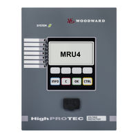
HighPROTEC MRU4
Woodward HighPROTEC MRU4 Manuals
Manuals and User Guides for Woodward HighPROTEC MRU4. We have
3
Woodward HighPROTEC MRU4 manuals available for free PDF download: Manual
Woodward HighPROTEC MRU4 Manual (574 pages)
Voltage Relay
Brand:
Woodward
| Category:
Relays
| Size: 12 MB
Table of Contents
MRU4 Functional Overview
2
Order Code
3
Table of Contents
4
Comments on the Manual
9
Information Concerning Liability and Warranty
9
Important Definitions
10
Scope of Delivery
13
Storage
14
Important Information
14
Symbols
15
General Conventions
21
Load Reference Arrow System
21
Device
22
Device Planning
22
Device Planning Parameters of the Device
23
Three-Side-View - 19
24
Installation and Connection
24
Three-Side-View - 8-Pushbutton Version
25
Installation Diagram 8-Pushbutton Version
26
Assembly Groups
27
Grounding
27
Legend for Wiring Diagrams
28
Slot X1: Power Supply Card with Digital Inputs
30
Slot X2: Relay Output Card
34
Slot X3: Voltage Transformer Measuring Inputs
37
Slot X100: Ethernet Interface
47
Slot X101: IRIG-B00X
49
Slot X103: Data Communication
51
Input, Output and LED Settings
61
Configuration of the Digital Inputs
61
Output Relays Settings
65
LED Configuration
88
Navigation - Operation
106
Basic Menu Control
110
Smart View Keyboard Commands
111
Smart View
112
Installation of Smart View
112
Uninstalling Smart View
112
Switching the Language of the Graphical User Interface
112
Setting up the Connection PC - Device
113
Loading of Device Data When Using Smart View
121
Restoring of Device Data When Using Smart View
122
Backup and Documentation When Using Smart View
123
Offline Device Planning Via Smart View
125
Measuring Values
126
Read out Measured Values
126
Statistics
132
Configuration of the Minimum and Maximum Values
132
Configuration of the Average Value Calculation
133
Direct Commands
135
Global Protection Parameters of the Statistics Module
135
States of the Inputs of the Statistics Module
137
Signals of the Statistics Module
137
Counters of the Module Statistics
138
System Alarms
143
Demand Management
143
Peak Values
146
Min. and Max. Values
146
THD Protection
147
Device Planning Parameters of the Demand Management
147
Signals of the Demand Management (States of the Outputs)
147
Global Protection Parameter of the Demand Management
148
States of the Inputs of the Demand Management
148
Acknowledgments
149
Manual Acknowledgment
151
Manual Acknowledgment Via Smart View
151
External Acknowledgments
152
External Acknowledge Via Smart View
152
Manual Resets
152
Manual Resets Via Smart View
153
Reset to Factory Defaults
153
Status Display
154
Status Display Via Smart View
154
Operating Panel (HMI)
155
Special Parameters of the Panel
155
Direct Commands of the Panel
155
Global Protection Parameters of the Panel
155
Recorders
156
Disturbance Recorder
156
Fault Recorder
166
Trend Recorder
172
Event Recorder
177
Communication Protocols
180
SCADA Interface
180
Modbus
181
Profibus
188
Iec60870-5-103
202
Iec61850
207
Time Synchronisation
216
Sntp
222
Irig-B00X
229
Parameters
233
Parameter Definitions
233
Access Authorizations (Access Areas)
249
Passwords - Areas
249
How to Find out What Access Areas/Levels Are Unlocked
252
Unlocking Access Areas
253
Changing Passwords
253
Changing Passwords Via Smart View
254
Password Entry at the Panel
254
Password Forgotten
254
Parameter Setting at the HMI
255
Parameter Setting Via Smart View
259
Setting Groups
262
Comparing Parameter Files Via Smart View
273
Converting Parameter Files Via Smart View
273
Setting Lock
274
Device Parameters
275
Date and Time
275
Synchronize Date and Time Via Smart View
275
Version
275
Version Via Smart View
275
TCP/IP Settings
276
Direct Commands of the System Module
277
Global Protection Parameters of the System
278
System Module Input States
280
System Module Signals
281
Special Values of the System Module
282
Field Parameters
283
General Field Parameters
283
Field Parameters - Voltage Related
284
Blockings
287
Permanent Blocking
287
Temporary Blocking
287
To Activate or Deactivate the Tripping Command of a Protection Module
289
Activate, Deactivate Respectively Block Temporarily Protection Functions
290
Module: Protection (Prot)
291
Direct Commands of the Protection Module
298
Global Protection Parameters of the Protection Module
298
Protection Module Input States
299
Protection Module Signals (Output States)
299
Protection Module Values
299
Switchgear/Breaker - Manager
300
Single Line Diagram
300
Switchgear Configuration
300
Switchgear Wear
312
Control Parameters
316
Controlled Circuit Breaker
327
Control - Example: Switching of a Circuit Breaker
337
Protective Elements
340
Interconnection
340
Voltage Protection [27/59]
341
VG, VX - Voltage Supervision [27A, 27TN/59N, 59A]
352
F - Frequency [81O/U, 78, 81R]
361
012 - Voltage Asymmetry [47]
385
Sync - Synchrocheck [25]
391
LVRT - Low Voltage Ride through
415
Intertripping (Remote)
429
Exp - External Protection
434
Supervision
440
CBF- Circuit Breaker Failure [50BF*/62BF]
440
TCS - Trip Circuit Supervision [74TC]
462
VTS - Voltage Transformer Supervision [60FL]
470
Self Supervision
476
General Description
478
Programmable Logic
478
Programmable Logic at the Panel
482
Programmable Logic Via Smart View
483
Commissioning
488
Commissioning/Protection Test
489
Putting out of Operation - Plug out the Relay
490
Service and Commissioning Support
490
Forcing Rtds
493
Forcing Analog Outputs
494
Forcing Analog Inputs
495
Failure Simulator (Sequencer)
496
Technical Data
506
Climatic Environmental Conditions
506
Degree of Protection en 60529
506
Routine Test
506
Housing
507
Voltage and Residual Voltage Measurement
508
Frequency Measurement
508
Voltage Supply
509
Power Consumption
509
Display
509
Front Interface RS232
509
Real Time Clock
509
Digital Inputs
510
Binary Output Relays
511
Time Synchronization IRIG
511
Rs485
512
Fibre Optic
512
URTD-Interface
512
Boot Phase
512
Standards
513
Approvals
513
Design Standards
513
High Voltage Tests (IEC 60255-6)
513
EMC Immunity Tests
514
EMC Emission Tests
514
Environmental Tests
515
Mechanical Tests
516
Assignment List
517
Signals of the Digital Inputs and Logic
553
Specifications
562
Specifications of the Real Time Clock
562
Time Synchronisation Tolerances
562
Specifications of the Measured Value Acquisition
563
Protection Elements Accuracy
564
Abbreviations, and Acronyms
567
List of ANSI Codes
572
Advertisement
Woodward HighPROTEC MRU4 Manual (323 pages)
Voltage / Frequency Protection
Brand:
Woodward
| Category:
Power distribution unit
| Size: 7 MB
Table of Contents
Table of Contents
4
Comments on the Manual
9
Information Concerning Liability and Warranty
9
Important Definitions
10
Scope of Delivery
14
Storage
14
Important Information
14
Symbols
15
Device
19
Device Planning
19
Device Planning Parameters of the Device
20
Installation and Connection
21
Three-Side-View
21
Installation Diagram
22
Assembly Groups
23
Grounding
24
Power Supply and Digital Inputs
25
Binary Output Relays, System Contact and IRIG
27
Voltage Measuring Inputs
29
PC Interface
31
Assignment of the Zero Modem Cable
32
Communication Interfaces
33
Modbus® RTU / IEC 60870-5-103 Via Terminals
33
Profibus DP / Modbus® RTU / IEC 60870-5-103 Via D-SUB-Plug
35
Voltage Transformers
36
Check of the Voltage Measuring Values
36
Wiring Examples of the Voltage Transformers
37
Navigation - Operation
43
Basic Menu Control
47
Smart View Keyboard Commands
48
Smart View
49
Installation of Smart View
49
Uninstalling Smart View
49
Switching the Language of the Graphical User Interface
49
Setting up the Connection PC - Device
50
Set-Up a Connection Via Ethernet - TCP/IP
50
Set-Up a Connection Via Serial Interface under Windows 2000
51
Set up a Connection Via Serial Interface under Windows XP
53
Set up a Connection Via Serial Interface under Windows Vista
54
Connected to the Device and Calling up Websites at the same Time
56
Establishing the Connection Via a USB-/RS232-Adapter
56
Smart View Troubleshooting
57
Smart View Persistent Connection Problems
59
Loading of Device Data When Using Smart View
60
Restoring of Device Data When Using Smart View
61
Backup and Documentation When Using Smart View
62
Printing of Device Data When Using Smart View (Setting List)
63
Saving Data as a Txt-File Via Smart View
63
Offline Device Planning Via Smart View
64
Measuring Values
65
Read out Measured Values
65
Read out of Measured Values Via Smart View
65
Standard Measured Values
66
Statistics
68
Read out Statistics
68
Statistics to be Read-Out Via Smart View
68
Statistics (Configuration)
69
Statistics (Configuration) Via Smart View
69
Direct Commands
70
Standard Statistic Values
70
Global Protection Parameters of the Statistics Module
73
States of the Inputs of the Statistics Module
74
Signals of the Statistics Module
74
Counters of the Module Statistics
74
Acknowledgments
75
Manual Acknowledgment
77
Manual Acknowledgment Via Smart View
77
External Acknowledgments
78
External Acknowledge Via Smart View
78
Manual Resets
79
Manual Resets Via Smart View
79
Assignment List
80
Status Display
93
Status Display Via Smart View
93
Module: Digital Inputs (Dis)
94
Digital Inputs (Standard)
95
Global Protection Parameters of the Digital Inputs (Standards)
95
Digital Input Signals (Output States)
98
Binary Output Relays
99
System Contact
101
Global Protection Parameters of the Binary Output Relays
102
Binary Output Relay Input States
114
Binary Output Relay Signals
119
Light Emitting Diodes (Leds)
120
The "System OK" LED
123
Global Protection Parameters of the LED Module
124
LED Module Input States
135
Operating Panel (Hmi)
139
Special Parameters of the Panel
139
Direct Commands of the Panel
139
Global Protection Parameters of the Panel
139
Module: Disturbance Recorder
140
Read out Disturbance Records
143
Disturbance Recorder to be Read out by Smart View
144
Deleting Disturbance Records
145
Deleting Disturbance Records Via Smart View
145
Direct Commands of the Disturbance Recorder Module
146
Global Protection Parameters of the Disturbance Recorder Module
146
Disturbance Recorder Module Input States
148
Disturbance Recorder Module Signals
148
Special Parameters of the Disturbance Recorder
149
Module: Fault Recorder
150
Read out the Fault Recorder
151
Read out the Fault Recorder Via Smart View
151
Direct Commands of the Fault Recorder Module
153
Global Protection Parameters of the Fault Recorder Module
153
Fault Recorder Module Input States
155
Fault Recorder Module Signals
155
Module: Event Recorder
156
Read out the Event Recorder
157
Read out the Event Recorder Via Smart View
157
Direct Commands of the Event Recorder Module
159
Event Recorder Module Signals
159
Module: SCADA
160
Device Planning Parameters of the Serial Scada Interface
160
Global Protection Parameters of the Serial Scada Interface
160
Module: Modbus (Modbus)
161
Modbus® Protocol Configuration
161
Modbus RTU
162
Modbus TCP
163
Direct Commands of the Modbus
164
Global Protection Parameters of the Modbus
164
Modbus® Module Signals (Output States)
167
Modbus® Module Values
168
Module: Profibus
170
Direct Commands of the Profibus
171
Global Protection Parameters of the Profibus
171
Module Inputs of the Profibus
181
Profibus Module Signals (Output States)
184
Profibus Module Values
185
Module: IEC60870-5-103
187
IEC60870-5-103 Protocol Configuration
187
Global Protection Parameters of the IEC60870-5-103
189
IEC60870-5-103 Module Signals (Output States)
191
IEC60870-5-103 Module Values
192
Parameters
193
Parameter Definitions
193
Device Parameters
193
Field Parameters
193
Protection Parameters
193
Device Planning Parameters
194
Direct Commands
194
State of the Module Inputs
194
Signals
194
Adaptive Parameter Sets
195
Operational Modes (Access Authorization)
200
Operational Mode - "Display Only
200
Operation Mode - "Parameter Setting and Planning
200
Password
201
Password Entry at the Panel
201
Password Changes
201
Password Forgotten
201
Changing of Parameters - Example
202
Changing of Parameters When Using the Smart View - Example
203
Protection Parameters
205
Setting Groups
205
Setting Group Switch
205
Setting Group Switch Via Smart View
206
Copying Setting Groups (Parameter Sets) Via Smart View
207
Comparing Setting Groups Via Smart View
207
Comparing Parameter Files Via Smart View
208
Converting Parameter Files Via Smart View
208
Field Parameters
209
Blockings
212
Permanent Blocking
212
Temporary Blocking
212
To Activate or Deactivate the Tripping Command of a Protection Module
215
Activate, Deactivate Respectively Block Temporarily Protection Functions
216
Module: Protection (Prot)
217
Direct Commands of the Protection Module
224
Global Protection Parameters of the Protection Module
224
Protection Module Input States
226
Protection Module Signals (Output States)
226
Protection Module Values
227
Module: Trip Control (Tripcontrol)
228
Direct Commands of the Trip Control Module
231
Global Protection Parameters of the Trip Control Module
231
Trip Control Module Input States
234
Trip Control Module Signals (Outputs States)
235
Trip Control Module Values
235
V-Protection Module - Voltage Protection [27/59]
236
Device Planning Parameters of the Voltage Protection Module
238
Global Protection Parameters of the Voltage Protection Module
238
Setting Group Parameters of the Voltage Protection Module
239
Voltage Protection Module Input States
243
Voltage Protection Module Signals (Output States)
243
Commissioning: Overvoltage Protection [59]
244
Commissioning: Undervoltage Protection [27]
245
Ve-Protection Module - Residual Voltage [59N]
246
Device Planning Parameters of the Residual Voltage Supervision Module
248
Global Protection Parameters of the Residual Voltage Supervision Module
248
Setting Group Parameters of the Residual Voltage Supervision Module
249
Residual Voltage Supervision Module Input States
250
Residual Voltage Supervision Module Signals (Output States)
250
Commissioning: Residual Voltage Protection - Measured [59N]
251
Commissioning: Residual Voltage Protection - Calculated [59N]
252
F-Protection Module - Frequency [81O/U, 78, 81R]
253
Device Planning Parameters of the Frequency Protection Module
260
Global Protection Parameters of the Frequency Protection Module
260
Setting Group Parameters of the Frequency Protection Module
261
Frequency Protection Module Input States
264
Frequency Protection Module Signals (Output States)
264
Commissioning: Frequency Protection (Overfrequency) [ANSI 81O]
265
Commissioning: Frequency Protection (Underfrequency) [ANSI 81U]
265
Commissioning: Df/Dt
266
Commissioning: F< and -Df/Dt
267
Commissioning: Delta Phi
268
012 - Protection Module Asymmetry [47]
269
Device Planning Parameters of the Asymmetry Module
271
Global Protection Parameter of the Asymmetry-Module
271
Parameter Set Parameters of the Asymmetry Module
272
States of the Inputs of the Asymmetry Module
273
Signals of the Asymmetry Module (States of the Outputs)
274
Commissioning: Asymmetry Protection
275
Exp Protection Module - External Protection
276
Device Planning Parameters of the Module External Protection
278
Global Protection Parameters of the Module External Protection
278
Setting Group Parameters of the Module External Protection
279
Module External Protection Input States
280
Module External Protection Signals (Output States)
280
Commissioning: External Protection
281
Tcs-Supervision Module - Trip Circuit Supervision [74Tc]
282
Device Planning Parameters of the Trip Circuit Supervision Module
285
Global Protection Parameters of the Trip Circuit Supervision Module
285
Setting Group Parameters of the Trip Circuit Supervision Module
286
Trip Circuit Supervision Module Input States
287
Trip Circuit Supervision Module Signals (Output States)
287
Commissioning: Trip Circuit Supervision [74TC]
288
Vts-Supervision Module - Voltage Transformer Supervision [60Fl]
289
Device Planning Parameters of the Voltage Transformer Module
291
Global Protection Parameters of the Voltage Transformer Supervision Module
291
Setting Group Parameters of the Voltage Transformer Module
292
Voltage Transformer Supervision Module Input States
293
Voltage Transformer Module Signals (Output States)
293
Commissioning: Voltage Transformer Supervision (Via DI) [60FL]
294
Commissioning: Voltage Transformer Failure [60FL]
295
Device Parameters
296
Date and Time
296
Synchronize Date and Time Via Smart View
296
Version
296
Version Via Smart View
296
TCP/IP Settings
297
Direct Commands of the System Module
298
Global Protection Parameters of the System
299
System Module Input States
301
System Module Signals
302
Special Values of the System Module
303
Commissioning
304
Commissioning/Protection Test
305
Putting out of Operation - Plug out the Relay
306
Service
307
General
307
Self Supervision
308
Error Messages / -Codes
309
Technical Data
310
Climatic Environmental Conditions
310
Degree of Protection en 60529
310
Routine Test
310
Housing
310
Voltage Supply
311
Power Consumption
311
Real Time Clock
311
Display
311
Digital Inputs
312
Voltage and Residual Voltage Measurement
313
Frequency Measurement
313
Binary Output Relays
313
Time Synchronization IRIG
314
Front Interface RS232
314
Rs485
314
Boot Phase
314
Standards
315
Approvals
315
Design Standards
315
High Voltage Tests (IEC 60255-6)
315
EMC Immunity Tests
316
EMC Emission Tests
316
Environmental Tests
317
Mechanical Tests
318
Tolerances
319
Real Time Clock Tolerances
319
Phase-To-Earth and Residual Voltage Measurement
319
Frequency Measurement
319
Protection Stages Tolerances
320
Woodward HighPROTEC MRU4 Manual (373 pages)
Voltage Protection
Brand:
Woodward
| Category:
Power distribution unit
| Size: 4 MB
Table of Contents
Table of Contents
3
MRU4 – Voltage Protection
8
Comments on the Manual
9
Important Definitions
12
Symbols and Definitions
16
Symbols in Function Diagrams
17
Information about the Device
20
Order Form of the Device
22
Navigation – Operation
24
Front Panel Parts
25
Softkey Symbols
27
Modules, Settings, Signals and Values
28
Parameter Settings
32
Adaptive Parameter Sets
37
Status Display
40
Menu Structure
41
Device Planning
43
Field Parameters
44
Device Parameters
45
Reset Counters, Values and Records
46
Network Security
48
Passwords
49
Connection Passwords, Smart View Access
50
Access Level Passwords
52
Access Levels
54
Reset to Factory Defaults, Reset All Passwords
57
Measuring Values
64
Statistics
65
Smart View
67
Hardware
68
MRU4 – Installation and Wiring
73
Overview of Slots – Assembly Groups
74
Communication Protocol Codes
75
Legend for Wiring Diagrams
78
DI8-X Power Supply and Digital Inputs
81
BO-5 X - Assembly Group with 5 Binary Output Relays + 1 System Contact
86
TU – Voltage Measuring Inputs
89
Voltage Transformers
92
Slot X100: Ethernet Interface
96
Ethernet – RJ45
97
Slot X101
98
Irig-B00X
99
Slot X103: Data Communication
100
Modbus® RTU / IEC 60870-5-103 Via RS485
101
Profibus DP/ Modbus® RTU / IEC 60870‑5‑103 Via Fiber Optic
105
Profibus DP Via D‑SUB
106
Modbus® RTU / IEC 60870‑5‑103 Via D‑SUB
107
Ethernet / TCP/IP Via Fiber Optics
108
Input, Output and LED Settings
110
Configuration of the Digital Inputs
112
Output Relays Settings
116
Communication Protocols
119
TCP/IP Settings
120
Iec 61850
122
Dnp3
124
Application Example: Setting a Relay
127
Iec60870-5-103
131
Configurable Communication Protocols
134
Iec 60870‑5‑104
135
High Tech Line 3-Compatible Modbus Datapoint Mapping
143
Data-Point Mapping Using the SCADAPTER
144
Time Synchronization
146
Sntp
149
Irig-B00X
151
Protective Elements
153
General Alarms and General Trips
155
Blockings
160
Blocking the Tripping Command
162
Activate, Deactivate or Block a Protection Function Temporarily
163
Commissioning: Overvoltage Protection [59]
169
Commissioning: Undervoltage Protection [27]
170
VG, VX – Voltage Supervision [27A, 59A]
171
Commissioning: Residual Voltage Protection – Measured [59N]
173
F – Frequency [81O/U, 78, 81R]
175
Operating Modes "F<", "F
177
Operating Mode "Df/Dt
179
Operating Modes "F< and Df/Dt", "F> and Df/Dt
181
Operating Modes "F< and DF/DT", "F> and DF/DT
183
Operating Mode "Delta Phi" – [ANSI 78V]
186
Commissioning: Overfrequency [F>]
191
Commissioning: F< and -Df/Dt – Underfrequency and ROCOF
192
Commissioning: F> and Df/Dt – Overfrequency and ROCOF
193
Commissioning: F> and DF/DT – Overfrequency and DF/DT
194
V 012 – Voltage Asymmetry [47]
195
Commissioning: Asymmetry Protection
196
Sync - Synchrocheck [25]
198
Reconnection Module
204
LVRT – Low Voltage Ride through [27(T)]
209
Intertripping (Remote)
215
Commissioning: Intertripping
216
Exp - External Protection
217
Supervision
219
Commissioning Example: Supervision Scheme 50BF
221
TCS - Trip Circuit Supervision [74TC]
223
Commissioning: Trip Circuit Supervision [74TC]
224
VTS – Voltage Transformer Supervision [60FL]
226
Commissioning: Voltage Transformer Failure [60FL]
227
Phase Sequence Supervision
228
Control / Switchgear-Manager
229
Switchgear Control
230
Settings Within the Protection Device
233
Invisible Switch
236
Circuit Breaker
237
Disconnector (Isolator)
239
Disconnector-Earthing Combination
240
Earthing Switch
241
Fuse-Load Switch
242
Fuse-Load Switch – Disconnector
243
Fused-Disconnector (Isolator)
244
Load Switch
245
Load Switch – Disconnector
246
Three Position Switch
247
Withdrawable Circuit Breaker
249
Withdrawable Fuse Load Switch
251
Switchgear Configuration
252
Switchgear Wear
263
Control - Example: Switching of a Circuit Breaker
265
System Alarms
267
Disturbance Recorder
269
Fault Recorder
274
Event Recorder
279
Trend Recorder
280
Programmable Logic
281
Device Start (Reboot)
289
Self-Supervision Messages
291
Syslog
292
Device Taken out of Service ("Device Stopped")
294
Commissioning/Protection Test
296
Putting out of Operation – Plug out the Relay
297
Service and Commissioning Support
298
Disarming the Relay Output Contacts
299
Fault Simulator (Sequencer)
301
Servicing and Maintenance
304
Technical Data
306
Specifications / Tolerances
314
Specifications of the Measured Value Acquisition
315
Protection Elements Accuracy
316
Voltage-Related Protection
317
Frequency Protection
319
Miscellaneous Protection and Supervision
321
Approvals
323
Design Standards
324
Electrical Tests
325
Environmental Tests
328
Mechanical Tests
330
IEC 60870‑104 Interoperability
332
Physical Layer
333
Application Layer
334
Basic Application Functions
340
Abbreviations, and Acronyms
345
List of ANSI Codes
352
Revision History
355
Version: 3.4
360
Version: 3.0.B
363
Index
367
Advertisement
Advertisement
Related Products
Woodward MRU3-1
Woodward MRS1
Woodward highprotec MRI4
Woodward MRI3-ITE
Woodward MRN3 Series
Woodward MRN3-1
Woodward MRN3-2
Woodward MRIK3
Woodward MRG3-I
Woodward MRG3-IE
Woodward Categories
Controller
Control Unit
Relays
Control Systems
Industrial Equipment
More Woodward Manuals
Login
Sign In
OR
Sign in with Facebook
Sign in with Google
Upload manual
Upload from disk
Upload from URL