Sign In
Upload
Manuals
Brands
West Control Solutions Manuals
Temperature Controller
Pro-EC44
West Control Solutions Pro-EC44 Manuals
Manuals and User Guides for West Control Solutions Pro-EC44. We have
1
West Control Solutions Pro-EC44 manual available for free PDF download: User Manual
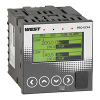
West Control Solutions Pro-EC44 User Manual (273 pages)
2-Loop Graphical Profile Controller & Recorder
Brand:
West Control Solutions
| Category:
Temperature Controller
| Size: 7.52 MB
Table of Contents
Warranty and Returns Statement
4
Table of Contents
5
Introduction
7
Installation
8
Unpacking
8
Panel-Mounting
8
Cleaning
9
Panel-Mounting the Instrument
9
Field Upgrade Options
10
Plug-Modules and Upgradeable Functions
10
Board Positions
10
Preparing to Install or Remove Plug-In Modules
11
Rear View (Uncased) & Board Positions
11
Main Board Connectors
12
Removing/Replacing Option Modules
13
Replacing the Instrument in Its Housing
13
Auto Detection of Plug-In Modules
13
Data Recorder Board
14
Profiler Enabling
14
Entering the Profiler Enable Code
14
Electrical Installation
15
Avoiding EMC Problems
15
Cable Isolation & Protection
15
Noise Suppression at Source
16
Transient Suppression with Inductive Coils
16
Contact Noise Suppression
16
Sensor Placement (Thermocouple or RTD)
17
Thermocouple Wire Identification
17
Thermocouple Wire Colour Chart
17
Pre-Wiring – Cautions, Warnings & Information
18
Connections and Wiring
19
Central Terminal Connections
19
Outer Terminal Connections
20
Power Connections
21
Power Connections - Mains Powered Instruments
21
Power Connections - 24/48V AC/DC Powered Instruments
21
Mains Power Connections
21
Universal Input 1 Connections
22
Universal Input 1 Connections - Thermocouple (T/C)
22
Universal Input 1 Connections – PT100 / NI120 (RTD) Input
22
Input 1 - RTD Connections
22
Universal Input 1 Connections - Linear Volt, MV or Ma Input
23
Universal / Auxiliary Input 2 Connections
23
Universal Input 2 Connections - Thermocouple (T/C)
23
Universal Input 2 Connections – PT100 / NI120 (RTD) Input
24
Universal / Auxiliary Input 2 Connections – Potentiometer
24
Base Option 1
25
Base Option 1 Relay Output 4
25
Base Option 1 Linear Output 6
25
Base Option 2 Relay Output 5
25
Plug-In Module Slot 1 – Single Relay Output Module
26
Plug-In Module Slot 1 – Single SSR Driver Output Module
26
Plug-In Module Slot 1 - Triac Output Module
27
Plug-In Module Slot 1 - Linear Voltage or Madc Output Module
27
Plug-In Module Slot 2 Connections
27
Plug-In Module Slot 2 – Single Relay Output Module
27
Plug-In Module Slot 2 - Dual Relay Output Module
28
Plug-In Module Slot 2 – Single SSR Driver Output Module
28
Plug-In Module Slot 2 – Dual SSR Driver Output Module
28
Plug-In Module Slot 2 - Triac Output Module
29
Plug-In Module Slot 2 - Transmitter Power Supply Module
29
Plug-In Slot 3 Connections
29
Plug-In Module Slot 3 – Single Relay Output Module
29
Plug-In Module Slot 3 - Dual Relay Output Module
30
Plug-In Module Slot 3 – Single SSR Driver Output Module
30
Plug-In Module Slot 3 – Dual SSR Driver Output Module
30
Plug-In Module Slot 3 - Triac Output Module
31
Plug-In Module Slot 3 - Transmitter Power Supply Module
31
Plug-In Slot a Connections
31
Plug-In Module Slot a – Basic Auxiliary Input Module
31
Plug-In Module Slot a - Ethernet Communications Module
32
Plug-In Module Slot a - RS485 Serial Communications Module
32
Plug-In Module Slot a – Single Digital Input Module
32
Option C Connections
33
Option C Connections – Multiple Digital Input Module
33
Special Wiring Considerations for Valve Motor Control
34
Interlocking of Valve Motor Drive Relays
34
Powering up Procedure
35
Front Panel Overview
35
Display
35
LED Functions
36
Keypad Functions & Navigation
36
Keypad Button Functions
36
Messages & Error Indications
37
Plug-In Module Problems
37
Sensor Break Detection
37
Un-Calibrated Input Detection
37
PV Over-Range or Under-Range Indication
37
Auxiliary Input Over-Range or Under-Range Indication
38
Cascade-Open
38
Profile Not Valid
38
USB Data Transfer Failure Message
38
Getting Help
38
Application Setup
39
Pre-Commissioning Considerations
39
How will the Instrument Physically Control the Process?
39
What Are the Sources for the Setpoints?
41
Is Input Re-Configuration Required?
41
Which Other Features Are to be Used?
41
Operation and Configuration Menus
42
Operation Mode
42
Navigating and Adjusting Values in Operator Mode
42
Operation Mode Screen Sequence
43
Calibration Check Due Warning
43
Single Control Loop: Normal Operation
43
Two Control Loops: Normal Operation
43
Cascade Control: Normal Operation
44
Ratio Control: Normal Operation
44
Single Control Loop: Profiler Status
44
Two Control Loops: Profiler Status
45
Entry into the Main Menu
48
Navigating the Main Menu
48
Unlock Codes
48
Main Menu Options
48
Manual Entry to the Setup Wizard
49
Navigating in the Setup Wizard
49
Setup Wizard Screens
49
Entry into Supervisor Mode
50
Navigating in Supervisor Mode
50
Supervisor Mode Screens
50
Configuration Menu
51
Entry into the Configuration Menu
51
Navigating the Configuration Menu
51
Input Configuration Sub-Menu Screens
52
Control Configuration Sub-Menu Screens
56
Outputs Configuration Sub-Menu Screens
62
Alarm Configuration Sub-Menu Screens
62
Communications Configuration Sub-Menu Screens
63
Data Recorder Configuration Sub-Menu Screens:
64
Clock Configuration Sub-Menu Screens
65
Display Configuration Sub-Menu Screens
65
The USB Menu
66
The USB Menu Is Entered from the Main Menu
66
Navigating in the USB Menu
66
Lock Code Configuration Sub-Menu Screen
66
Reset to Defaults Sub-Menu Screen
66
Entry into the USB Menu
66
Usb Menu Screens
67
Entry into the Recorder Control Menu
68
Recorder Menu Screens
68
Entry into the Profiler Setup Menu
69
Profiler Setup Menu Screens
69
Profiler Control Menu Screens
72
Entry into Service & Product Information Mode
73
Entry into the Automatic Tuning Menu
74
Automatic Tuning Menu Screens
74
Lost Lock Codes
75
Forcing Lock Code Configuration
75
Input Calibration & Multi-Point Scaling
76
User Calibration
76
Single Point Calibration
76
Calibration Reminder
76
Two Point Calibration
77
Multi-Point Scaling
78
Base Calibration Adjustment
78
Required Equipment
78
Performing a Calibration Check
79
Recalibration Procedure
79
Input Calibration Phases
79
Digital Inputs
81
Digital Signal Type
81
Inverting Digital Inputs
81
Soft Digital Inputs
82
Digital Input Functions
82
Single Functions
82
Profile Selection Via Digital Inputs
83
Using Binary to Select Profile Numbers
83
Using BCD to Select Profile Numbers
83
Cascade Control
84
Example Cascade Application
84
Cascade Example
84
Normal Cascade Operation
85
Manual Mode
85
Cascade Tuning
85
Cascade-Open
85
To Manually Tune a Cascade
86
Ratio Control
87
Stoichiometric Combustion
87
Ratio Control Example
87
Redundant Input
89
Valve Motor Drive / 3-Point Stepping Control
90
Position Feedback
91
Valve Limiting
91
Setpoint Sources
92
Loop 1 Setpoint Sources
92
Loop 2 Setpoint Sources
92
Loop 2 Profile Setpoint
92
Profilerprofile Components
93
Profile Header & Segment Information
93
Profile Starting & Standard Segments
94
Profile Starting and Standard Segment Types
94
Two Loop Profiles
95
Both Loops on same Time-Base
95
Loop-Back Segments
96
Profile Running / Holding Vs. Hold Segments
96
Run/Hold & Hold Segments
96
The Auto-Hold Feature
97
Auto Hold Examples
97
Auto-Hold on a Dwell Segment
97
Auto Hold on Ramps
98
Auto-Hold on a Ramp Segment
98
Profile Cycles & Repeat Sequences
98
Profile Cycles & Repeats
98
Power/Signal Lost Recovery Actions
99
Possible Recovery Methods
99
Profile End Actions
100
Possible Profile End Actions
100
Profile Abort Actions
101
Possible Profile Abort Actions
101
USB Interface
102
Using the USB Port
102
USB Memory Stick Folders & Files
102
Data Recorder
103
Recordable Values
103
Recorder Control and Status
103
Uploading Data
104
Additional Features & Benefits from the Recorder
104
Controller Tuning
105
PID Sets & Gain Scheduling
105
Automatic Tuning
106
Pre-Tune
106
Pre-Tune Operation
106
Auto Pre-Tune
107
Self-Tune
107
Self-Tune Operation
107
Manually Tuning
108
Tuning Control Loops - PID with Primary Output Only
108
Manually Tuning - PID with Primary Output
108
Tuning Control Loops - PID with Primary & Secondary Outputs
109
Method 1 – for Simple Processes
109
Method 2 – for Asymmetrical Processes
109
Valve, Damper & Speed Controller Tuning
110
Manually Tuning – PI Control
111
Fine Tuning
112
Cycle Times
112
Proportional Cycle Times
112
Proportional Bands
112
Integral Time Constant
113
Derivative Time Constant
113
Derivative Time
113
Integral Time
113
Anti Wind-Up
114
Manual Reset
114
Serial Communications
115
Supported Protocols
115
RS485 Configuration
115
RS485 Device Addressing
115
Link Layer
116
Modbus Link Layer
116
Supported Modbus Functions
117
Function Descriptions
117
Function 03 / 04 - Read Holding/Input Registers
117
Function 06 - Write Single Register
117
Function 08 - Loopback Diagnostic Test
118
Function 16 - Write Multiple Registers (0X10 Hex)
118
Function 23 Hex - Read / Write Multiple Registers (0X17 Hex)
118
Exception Responses
118
Modbus Parameters
119
Data Formats
119
Parameter Register Address Listings
119
Calibration Reminder Parameters
120
Universal Process Input 1 Parameters
120
Plug-In Module Slot 1 Parameters
143
Linear Output 6 Parameters
153
Linear Output 7 Parameters
154
Loop 1 Setpoint Parameters
155
Loop 2 Setpoint Parameters
156
Aux a Input Parameters
157
Loop 1 Control Parameters
157
Alarm Parameters
169
Profile Setup Via Modbus
193
Instruction Sequence to Edit an Existing Profile Header
194
Instruction Sequence to Read a Profile
195
Creating or Editing a Profile Header
195
Creating, Editing or Inserting Segments
197
Segment Data
198
Deleting All or Single Profiles
199
Delete a Segment
200
Get Segments Remaining
201
Edit Response Message from Instrument
201
Command Response Data
201
Read a Profile Header Request & Response Sequence
202
Glossary
210
Active Setpoint
210
Actual Setpoint
210
Alarm Activation Inhibit
210
Alarm Operation
212
Alarm Types
213
Alternate Setpoint
213
Auxiliary Input
213
Auxiliary Input Lower Limit
213
Auxiliary Input Offset
214
Auxiliary Input Type
214
Auxiliary Input Upper Limit
214
Bar Graphs
214
Calibration
215
Communications Write Enable
215
Control Configuration
216
Control Deviation
216
Control Action
216
Control Power Alarm
216
Controller
217
Controller Mode
217
Correcting Variable
217
Cycle Time
217
Derivative Action
218
Deviation Alarm
218
Direct Acting Control
218
Display Configuration
219
Display Languages
219
Display Resolution
219
Engineering Units
219
Indicator
220
Input Configuration
220
Input Filter Time Constant
220
Input Range
220
Invert Digital Input
221
Latching Output
221
Linear Input
221
Linear Output
221
Local Setpoints
222
Lock Codes
222
Logical Output Combinations
222
Examples of Logical Outputs
222
Loop Alarm
223
Lsd
223
Madc
223
Main Menu
223
Manual Loop Alarm Time
224
Master & Slave Controllers
224
Modbus RTU
225
Minimum Motor on Time
225
Modulating Valve
226
Motor Travel Time
226
MVDC
226
On-Off Control
226
On-Off Differential
227
On-Off Hysteresis
227
Output Configuration
227
PC Software
228
PD Control
229
PI Control
229
PID Control
229
PID Gain Sets
229
Power Output Limits
230
Primary Proportional Band
230
Process High Alarm
230
Process Inputs
230
Process Variable (PV)
231
Profile Control Menu
231
Profile Events
231
Profile Header
231
Profiler
232
Profiler Mode
232
Rate of Change Alarm
232
Recorder Configuration
233
Recorder Menu
233
Remote Setpoint (RSP)
233
Retransmit Output
233
Retransmit Output Scale Minimum
234
Reset to Defaults
234
Reverse Acting Control
234
Rs485
234
Scaled Input Upper Limit
235
Scaled Input Lower Limit
235
Secondary Proportional Band
235
Sensor Break Pre-Set Power
236
Serial Communications Configuration
236
Serial Communications Option
236
Set Valve Opened Position
236
Setpoint Upper Limit
237
Setpoint Lower Limit
237
Setpoint Ramp Rate
237
Solid State Relay (SSR)
238
Solenoid Valve
238
Thermocouple
238
Time Proportioning Control
239
Trend Displays
239
Tuning
239
Tuning Menu
239
Triac
240
USB Menu
240
Valve Motor Drive Control (VMD)
240
Valve Position or Flow Indication
240
Using the PC Software
241
Main Parameter Screen
241
Instrument Simulation
242
Button Bar & View Menu
242
Configuring the Connection
242
West Pro-EC44 Instrument Simulation
242
Connection from PC to Bottom Configuration Socket
243
Connection from PC to Rear RS485 Communications Option
243
Connection from Pc/Network to Ethernet Port
244
Changing the IP Address
244
Instrument Configuration
245
Main Parameter Adjustment
245
Extending Functionality Via Software
246
LED Functions & Labels
246
Alarm Status Screen Labels
246
Configuring the Supervisor Mode
246
Changing the Start-Up Splash Screen
247
Changing the Alternate Display Language
247
Supervisor/Enhanced Operation Mode Configuration
247
Profile Creation and Editing
248
Profile Editor – Header
248
Data Recorder Trend Upload & Analysis
249
Analysing Data
249
Project Documentation
250
Specifications
251
Reference Test Conditions
251
Universal Process Inputs
251
Thermocouple Input
251
Thermocouple Performance
252
Resistance Temperature Detector (RTD) Input
252
RTD Types & Ranges
252
DC Linear Input
252
DC Linear Performance
253
Input Functions
253
Auxiliary Input a Types & Ranges
253
Auxiliary Input Performance
253
Digital Input Performance
254
Output Specifications
255
Output Module Types
255
Single Relay Output 1-3 Performance
255
Dual Relay Output 2-3 Performance
255
Dual SSR Driver Output 2-3 Performance
256
Triac Output 1-3 Performance
256
Single DC Linear Output Types & Ranges
256
DC Linear Output 1, 6-7 Performance
256
24V Transmitter Power Supply 2-3 Performance
257
Communications
257
Supported Communication Methods
257
Operating Conditions
260
24 Pro-EC44 Product Coding
261
Table of Contents
263
Pro-EC44 Product Manual - 59540-2 September 2014
265
Advertisement
Advertisement
Related Products
West Control Solutions ProVU4
West Control Solutions PMA Relay C
West Control Solutions Categories
Temperature Controller
Controller
Relays
More West Control Solutions Manuals
Login
Sign In
OR
Sign in with Facebook
Sign in with Google
Upload manual
Upload from disk
Upload from URL