
Related Manuals for West Control Solutions Pro-EC44

Summary of Contents for West Control Solutions Pro-EC44
- Page 1 Pro-EC44 2-Loop Graphical Profile Controller & Recorder Pro-EC44 User Guide 59540-2...
- Page 3 Danaher/West Control Solutions. Copies of this manual are available in electronic format on the West Control Solutions web site (www.west-cs.com) Printed versions may be purchased from West Control Solutions or its representatives.
- Page 4 Pro-EC44 2-Loop Graphical Profile Controller & Recorder Warranty and Returns Statement These products are sold by West Control Solutions under the warranties set forth in the following paragraphs. Such warranties are extended only with respect to a purchase of these...
-
Page 5: Table Of Contents
Pro-EC44 2-Loop Graphical Profile Controller & Recorder How to use this manual This manual is structured to give easy access to the information required for all aspects of the installation and use and of the controller. The main sections are shown here, with a full table of contents at the end. -
Page 7: Introduction
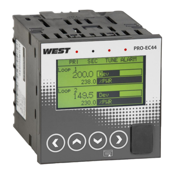
Pro-EC44 2-Loop Graphical Profile Controller & Recorder 1 Introduction This product is a DIN size (96 x 96mm front) microprocessor based graphical process controller, featuring a 160 x 80 pixel, monochrome LCD with dual colour (red/green) backlight. It operates from 100-240V at 50/60 Hz or 24V-48V AC/DC, depending on the model purchased. -
Page 8: Installation
Pro-EC44 2-Loop Graphical Profile Controller & Recorder 2 Installation Unpacking 1. Remove the product from its packing. Retain the packing for future use, in case it is necessary to transport the instrument to a different site or to return it to the supplier for servicing. - Page 9 Pro-EC44 2-Loop Graphical Profile Controller & Recorder Instruments may be mounted side-by-side in a multiple installation, but instrument to panel moisture and dust sealing will be compromised. Allow a 20mm gap above, below and behind the instrument for ventilation. The cut-out width (for n instruments) is: (96n - 4) mm or (3.78n - 0.16) inches...
-
Page 10: Field Upgrade Options
Pro-EC44 2-Loop Graphical Profile Controller & Recorder 3 Field Upgrade Options Plug-Modules and Upgradeable Functions Plug-Modules can be either pre-installed at the time of manufacture, or retrofitted in the field to expand the capabilities of the controller. Contact your supplier to purchase these items. - Page 11 Pro-EC44 2-Loop Graphical Profile Controller & Recorder Board Mounting Struts (x4) Front Panel Removal Latch (x1) Plug-in Module A Plug-in Module 3 Power Supply Board 2nd Universal Input & Base Option 2 Board 1st Universal Input & Base Option 1 Board...
- Page 12 Pro-EC44 2-Loop Graphical Profile Controller & Recorder Main Board Connectors POWER SUPPLY Module Slot 3 BOARD Connector PL4B Transformer Colour Code Module Slot A 100-240V (Yellow) Connectors PL5, & PL6 24-48V(Blue) Module Slot 1 Connectors PL7 & PL8 Display Board...
- Page 13 Pro-EC44 2-Loop Graphical Profile Controller & Recorder Removing/Replacing Option Modules 1. To remove or replace Plug-in Modules 1, 2, 3 or A it is necessary to detach the power supply and input boards from the front panel by lifting first the upper and then lower mounting struts.
- Page 14 Pro-EC44 2-Loop Graphical Profile Controller & Recorder Data Recorder Board If installed, the Data Recorder memory and Real Time Clock (RTC) components are located on a plug-in daughter board attached to the front Display/CPU board. CAUTION: Servicing of the Data Recorder/RTC circuit and replacement of the lithium battery should only be carried out by a technically competent technician.
-
Page 15: Electrical Installation
Pro-EC44 2-Loop Graphical Profile Controller & Recorder 4 Electrical Installation CAUTION: Installation should be only performed by technically competent personnel. It is the responsibility of the installing engineer to ensure that the configuration is safe. Local Regulations regarding electrical installation &... - Page 16 Pro-EC44 2-Loop Graphical Profile Controller & Recorder Noise Suppression at Source If possible, eliminate mechanical contact relays and replace with solid-state relays. Noise-generating devices such as Ignition transformers, arc welders, motor drives, relays and solenoids should be mounted in a separate enclosure. If this is not possible, separate them from the instrumentation, by the largest distance possible.
- Page 17 Pro-EC44 2-Loop Graphical Profile Controller & Recorder Sensor Placement (Thermocouple or RTD) If a temperature probe is to be subjected to corrosive or abrasive conditions, it must be protected by an appropriate thermowell. Probes must be positioned to reflect the true process temperature: 1.
- Page 18 Pro-EC44 2-Loop Graphical Profile Controller & Recorder Pre-wiring – Cautions, Warnings & Information CAUTION: Installation should be only performed by technically competent personnel. It is the responsibility of the installing engineer to ensure that the configuration is safe. Local Regulations regarding electrical installation &...
- Page 19 Pro-EC44 2-Loop Graphical Profile Controller & Recorder Connections and Wiring Central Terminal Connections Note: The wiring diagram below shows all possible combinations to the main connections (numbered 1 to 24) in the centre of the case rear. The actual connections required depends upon the features and modules fitted.
- Page 20 Pro-EC44 2-Loop Graphical Profile Controller & Recorder Outer Terminal Connections Note: The wiring diagram below shows the Central Terminals (numbered 25 to 42) at the sides of the case rear. Connections for the 2 Input, Base Option 2 and Digital Input C are shown. The actual connections required depends upon the features and modules fitted.
- Page 21 Pro-EC44 2-Loop Graphical Profile Controller & Recorder Power Connections WARNING: CHECK THE INFORMATION LABEL ON THE CASE TO DETERMINE THE CORRECT VOLTAGE BEFORE CONNECTING TO A LIVE SUPPLY. CAUTION: This equipment is designed for installation in an enclosure that provides adequate protection against electric shock. An isolation switch should be located in close proximity to the unit, in easy reach of the operator and appropriately marked.
- Page 22 Pro-EC44 2-Loop Graphical Profile Controller & Recorder Universal Input 1 Connections Universal Input 1 is present on all models. This input is normally used for the measured variable signal from a process to be controlled. It can be connected to thermocouples;...
- Page 23 Pro-EC44 2-Loop Graphical Profile Controller & Recorder Universal Input 1 Connections - Linear Volt, mV or mA input The input supports the following linear/analogue signals: 0 to 50mV; 10 to 50mV; 0 to 5V; 1 to 5V; 0 to 10V; 2 to 10V; 0 to 20mV; 4 to 20mA from any suitable source. Voltage & millivolt signals are connected to terminals 2 &...
- Page 24 Pro-EC44 2-Loop Graphical Profile Controller & Recorder Universal Input 2 Connections – PT100 / NI120 (RTD) input universal input, supports two types of RTD. PT100 (platinum sensor, 100Ω The optional 2 at 0°C). For three wire RTDs, connect the resistive leg and the common legs of the RTD as illustrated.
- Page 25 Pro-EC44 2-Loop Graphical Profile Controller & Recorder Base Option 1 Base Option 1 provides one or two factory fitted outputs. A relay designated as Output 4 is fitted on all models, and an optional linear mA/V DC designated as Output 6. Base options cannot be added after manufacture.
- Page 26 Pro-EC44 2-Loop Graphical Profile Controller & Recorder Base Option 2 Linear Output 7 Part of base option 2, Output 7 is an optional linear mV/V DC analogue output. The type & range are selectable from 0 to 5, 0 to 10, 2 to 10V & 0 to 20 or 4 to 20mA.
- Page 27 Pro-EC44 2-Loop Graphical Profile Controller & Recorder Plug-in Module Slot 1 - Triac Output Module If fitted with a triac output module, connect as shown. This output is rated at 0.01 to 1 amp @ 280V AC 50/60Hz. Isolated from all other inputs and outputs. A snubber should be fitted across inductive loads to ensure reliable switch off of the Triac.
- Page 28 Pro-EC44 2-Loop Graphical Profile Controller & Recorder Plug-in Module Slot 2 - Dual Relay Output Module If fitted with a dual relay output module, connect as shown. This module has two independent SPST relays for outputs 2A and 2B, with a shared common terminal. The contacts are rated at 2 amp resistive 240 VAC.
- Page 29 Pro-EC44 2-Loop Graphical Profile Controller & Recorder Plug-in Module Slot 2 - Triac Output Module If fitted with a Triac output module, connect as shown. This output is rated at 0.01 to 1 amp @ 280V AC 50/60Hz. Isolated from all other inputs and outputs. A snubber should be fitted across inductive loads to ensure reliable switch off of the Triac.
- Page 30 Pro-EC44 2-Loop Graphical Profile Controller & Recorder Plug-in Module Slot 3 - Dual Relay Output Module If fitted with a dual relay output module, connect as shown. This module has two independent SPST relays for outputs 3A and 3B, with a shared common terminal. The contacts are rated at 2 amp resistive 240 VAC.
- Page 31 Pro-EC44 2-Loop Graphical Profile Controller & Recorder Plug-in Module Slot 3 - Triac Output Module If fitted with a Triac output module, connect as shown. This output is rated at 0.01 to 1 amp @ 280V AC 50/60Hz. Isolated from all other inputs and outputs. A snubber should be fitted across inductive loads to ensure reliable switch off of the Triac.
- Page 32 Pro-EC44 2-Loop Graphical Profile Controller & Recorder Plug-in Module Slot A - Ethernet Communications Module If fitted with the Ethernet communication module, the communications protocol available is Modbus TCP. Isolated from all inputs/outputs. If necessary, cut out the removable panel to access the RJ45 connector through the top of the case.
- Page 33 Pro-EC44 2-Loop Graphical Profile Controller & Recorder Option C Connections Option C offers a factory fitted multiple digital input option. The board also accommodates the USB port if that is option is fitted. The USB port does not have connections on the rear terminal, it is accessed via the front panel.
- Page 34 Pro-EC44 2-Loop Graphical Profile Controller & Recorder Special Wiring Considerations for Valve Motor Control Valve Motor Drive (VMD) controllers require two identical outputs to be assigned to position the valve. One to open and one to close the valve. These outputs can be two single relays, two triacs, two SSR drivers or one dual relay, but it is recommended to use two single relays (SPDT change-over contacts), and to interlock the relay wiring as shown.
-
Page 35: Powering Up
Pro-EC44 2-Loop Graphical Profile Controller & Recorder 5 Powering Up CAUTION: Ensure safe wiring practices have been followed. When powering up for the first time, disconnect the output connections. The instrument must be powered from a supply according to the wiring label on the side of the unit. -
Page 36: Led Functions
Pro-EC44 2-Loop Graphical Profile Controller & Recorder LED Functions There are four red LEDs that by default indicate the status of the primary & secondary outputs, automatic tuning and alarm status. The top line of the graphical display has four labels for LED indicators. -
Page 37: Messages & Error Indications
Pro-EC44 2-Loop Graphical Profile Controller & Recorder 6 Messages & Error Indications Plug-in Module Problems If an invalid or unknown module is detected in one of the plug-in module slots during the power-up self-test, the message “Fault Found, Press R, for details” is shown. This is followed by “Replace faulty module in Module Slot n, Press R,”... - Page 38 Pro-EC44 2-Loop Graphical Profile Controller & Recorder Auxiliary Input Over-range or Under-range Indication If the auxiliary Remote Setpoint input is more than 5% above than the Auxiliary Input Upper Limit, its value is replaced by the word “HIGH” to indicate that it is out of range.
-
Page 39: Application Setup
Pro-EC44 2-Loop Graphical Profile Controller & Recorder 7 Application Setup Before beginning configuration, consider how the controller will be used in your application. For instance, how many control loops are needed, is cascade or ratio control required, will the unit control a valve motor, do you need setpoint profiling etc. Consideration should also be given to the output types, alarms and tuning method. - Page 40 Pro-EC44 2-Loop Graphical Profile Controller & Recorder Process Type* Loop 1 / Master Loop 2 / Slave (only if 2nd Control Control Control Control input fitted) Configuration: Configuration: Configuration: Configuration: Control Select Control Type Control Select Control Type Two Loops*...
- Page 41 Pro-EC44 2-Loop Graphical Profile Controller & Recorder What are the sources for the setpoints? Local setpoint(s) only, or a remote setpoint input (see page 216 & 227). Profile Control (see page 87). Is Input re-configuration required? Analogue input calibration & scaling (see page 70).
-
Page 42: Operation And Configuration Menus
Pro-EC44 2-Loop Graphical Profile Controller & Recorder 8 Operation and Configuration Menus This section contains information on all of the controller’s modes and the configuration menus. Operation Mode This is the mode used during normal operation of the instrument. It can be accessed from the Main Menu, and is the usual mode entered at power-up. - Page 43 Pro-EC44 2-Loop Graphical Profile Controller & Recorder OPERATION MODE SCREEN SEQUENCE All possible screens are listed below. The sequence shown depends on the configuration and status. E.g. settings for “Loop 2” only apply if 2nd input is fitted and configured for 2-loop control.
- Page 44 Pro-EC44 2-Loop Graphical Profile Controller & Recorder Cascade Control: Normal Operation LED Indicators LED Function Labels Master Process Value Cascade Status Slave Process Value Master Setpoint (Slave SP if Cascade Open) Control Deviation (±5% of span) & Power Graphs CASCADE CONTROL Default LED indicator functions are PRI, SEC, TUNE &...
- Page 45 Pro-EC44 2-Loop Graphical Profile Controller & Recorder Two Control Loops: Profiler Status LED Indicators LED Function Labels Engineering Units* Profile Status Indicators*: ■ ► Run, Process Variable Values & Held, ▌▌ Setpoints* Stopped Loop Descriptions* Profile Name & Progress Segment No.
- Page 46 Pro-EC44 2-Loop Graphical Profile Controller & Recorder Setpoint Ramp Rate The setpoint ramp rate adjustment for loop 1. Adjustable between 0.1 and – Loop 1 9999.0 display units per hour. When set to “OFF”, setpoint changes will step ◘ only shown if set to do so in Display.
- Page 47 Pro-EC44 2-Loop Graphical Profile Controller & Recorder Hold down D or U for 3 seconds to clear the selected latched output – An Clear Latched Outputs output will only reset if the condition that caused it to latch on is no-longer ◘...
-
Page 48: Main Menu
Pro-EC44 2-Loop Graphical Profile Controller & Recorder Main Menu This menu is used to access the various features and configuration settings. The available menus are dependent upon the features and options fitted and how it has been configured. Entry into the Main Menu... - Page 49 Pro-EC44 2-Loop Graphical Profile Controller & Recorder Setup Wizard An easy Setup Wizard runs automatically at first ever power-up. Follow the Wizard to setup parameters required for basic applications. The parameters covered by the Setup Wizard are marked with a w in the following sections covering the configuration mode sub-menus. Once completed, the Setup Wizard exits to Operation Mode.
- Page 50 Pro-EC44 2-Loop Graphical Profile Controller & Recorder Supervisor Mode This mode is only available if it has been configured from the PC software. Its purpose is to allow selected operators access to a lock-code protected sub-set of the configuration parameters, without providing them with the higher level configuration menu unlock code.
- Page 51 Pro-EC44 2-Loop Graphical Profile Controller & Recorder Configuration Menu This menu can be used as an alternative to the more limited Setup Wizard when the instrument is configured for the first time in more complex applications, or when further changes are required to the instruments settings. The configuration menu contains a number of sub-menus that allow access to all of the available parameters.
- Page 52 Pro-EC44 2-Loop Graphical Profile Controller & Recorder CONFIGURATION MENU SCREENS: Configuration Mode Enter correct code number to access Configuration Mode. Unlocking Factory Default value is 10. Configuration Select the required Configuration Sub-Menu Option from: Inputs; Control; Options Outputs; Alarm; Communications; Recorder; Clock; Display; Lock Code or Reset To Defaults.
- Page 53 Pro-EC44 2-Loop Graphical Profile Controller & Recorder Input 2 Setup - Sub-menu to setup Input 2. Press D + R to return to Input Menu Input 2 Usage w Input 2 can be used as a standard process input for a second control loop (including its use as part of a cascade), a redundant input or a feedback signal input from a valve or flow meter.
- Page 54 Pro-EC44 2-Loop Graphical Profile Controller & Recorder Input 2 Calibration - Sub-menu to calibrate Input 2. Press D + R to return to Input Menu Calibration Type If input 2 is selected as a standard process input, the user can select the calibration type from base;...
- Page 55 Pro-EC44 2-Loop Graphical Profile Controller & Recorder Digital Input Setup - Sub-menu to setup the Digital Inputs. Press D + R to return to Input Menu A diagnostic status ( = OFF, = ON, Ø = not available) for digital inputs Digital Input Status A;...
- Page 56 Pro-EC44 2-Loop Graphical Profile Controller & Recorder CONTROL CONFIGURATION SUB-MENU SCREENS Control Loop 1 - Sub-menu to setup Control Loop 1. Press D + R to return to Input Menu These settings apply to the master loop if the controller has been setup for cascade control.
- Page 57 Pro-EC44 2-Loop Graphical Profile Controller & Recorder Set n – Integral The integral time value (Automatic Reset) for PID Set n (n = up to 5). Adjustable from 1s to 99min 59s or OFF – Only the set(s) in use shown.
- Page 58 Pro-EC44 2-Loop Graphical Profile Controller & Recorder Secondary Power The minimum secondary output power limit. The control algorithm will not Lower Limit allow the power output fall below this level. Adjustable from 0 to 90% but is always at least 10% below the secondary power upper limit.
- Page 59 Pro-EC44 2-Loop Graphical Profile Controller & Recorder Select if the main or alternate setpoint is to be the current “active” setpoint Select Active Setpoint for this loop. Main Setpoint Offset An offset that can be added to the main setpoint (+ve values) or subtracted from it (-ve values) when the instrument is a comms slave in a multi-zone application.
- Page 60 Pro-EC44 2-Loop Graphical Profile Controller & Recorder Set n – Integral The integral time value (Automatic Reset) for PID Set n (n = up to 5). Adjustable from 1s to 99min 59s or OFF – Only the set(s) in use shown.
- Page 61 Pro-EC44 2-Loop Graphical Profile Controller & Recorder Power Output remote setpoint input is lost. Adjustable from 0 to 100% for single control or -100 to +100% for dual control. The default value is OFF (0% power). Does not apply if control is disabled or in manual mode.
- Page 62 Pro-EC44 2-Loop Graphical Profile Controller & Recorder OUTPUTS CONFIGURATION SUB-MENU SCREENS Output n Configuration - Up to 9 outputs listed. Any already used show as “Assigned” but can be changed. If “Digital” is shown, the output is driven directly via a digital input (see input configuration).
- Page 63 Pro-EC44 2-Loop Graphical Profile Controller & Recorder The Alarm n activation point – The value is limited by the scaled input limits Alarm n Value for Process High; Process Low; PV-SP Deviation (+ve above, -ve below setpoint), Band (above or below setpoint) type alarms.
- Page 64 Pro-EC44 2-Loop Graphical Profile Controller & Recorder DATA RECORDER CONFIGURATION SUB-MENU SCREENS: No Recorder If the Recorder Configuration menu is entered on an instrument without this Warning option fitted. Recording In A warning if recording when attempting to enter recorder configuration. - Progress Warning Access to the configuration is denied unless the recording is paused.
- Page 65 Pro-EC44 2-Loop Graphical Profile Controller & Recorder Activities To Record Multiple process events can be recorded from: Alarm n Status (n = 1 to 7) or Unit turned Off/On. Note: If an alarm changes state an extra sample is recorded using extra memory.
- Page 66 Pro-EC44 2-Loop Graphical Profile Controller & Recorder LOCK CODE CONFIGURATION SUB-MENU SCREEN Lock Code Set Lock Codes (passwords) for the following configuration and control Configuration menus: Setup Wizard; Configuration Mode; Tuning Menu; Supervisor Mode; USB Menu; Recorder Menu, Profiler Setup and Profiler Menu.
- Page 67 Pro-EC44 2-Loop Graphical Profile Controller & Recorder Note: During Data Transfer, normal operation carries on in the background, but operator access to other screens is not possible. The transfer of a full memory can take up to 20 minutes. Only begin a transfer when you are certain that access (e.g.
- Page 68 Pro-EC44 2-Loop Graphical Profile Controller & Recorder Recorder Control Menu This menu allows the user to manually start a recording or to delete previous recordings. Refer to the Recorder Configuration sub-menu in Configuration Mode for information about how to setup the data to be recorded and the recording interval and the Data Recorder Option section on page 97 for general information about the recorder feature.
- Page 69 Pro-EC44 2-Loop Graphical Profile Controller & Recorder Recorder Status Current information about the data recorder feature, including if a recording Information is in progress (Recording or Stopped); the recording mode (FIFO or Record Until Memory Is Used); a % memory use bar-graph and the estimated available time remaining based on the data selected and memory left.
- Page 70 Pro-EC44 2-Loop Graphical Profile Controller & Recorder General Profile Sub-menu with global settings affecting all profiles. Press D + R to return to Profile Setup Menu Configuration Enable Edit Enables or disables the ability to edit profiles whist a profile is running.
- Page 71 Pro-EC44 2-Loop Graphical Profile Controller & Recorder Profile Segments: Settings that apply to individual profile segments Shows the number of the profile segment being created. The maximum Segment Number number of profiles across all profiles is 255. Segment Type Set the segment type from: Ramp Time (time to reach target SP); Ramp Rate (rate of change towards target SP –...
- Page 72 Pro-EC44 2-Loop Graphical Profile Controller & Recorder Select the events to be active during this segment. n = 1 to 5. Event n Note: For end segments, the events selected to be active stay on until the instrument exits from profiler mode or a new profile runs.
- Page 73 Pro-EC44 2-Loop Graphical Profile Controller & Recorder Service & Product Information Mode This is read only information about the instrument, its modules and enabled features. It has contact information to tell the user where they can obtain service, sales or technical support for the product.
- Page 74 Pro-EC44 2-Loop Graphical Profile Controller & Recorder Automatic Tuning Menu The automatic tune menu is used to engage pre-tune and/or self-tune to assist setting up proportional bands and the integral and derivative time values used by the control loops. Pre-tune can be used to set PID parameters approximately. Self-tune may then be used to optimise the tuning if required.
- Page 75 Pro-EC44 2-Loop Graphical Profile Controller & Recorder Engage Self-Tune Turns self-tune on/off for the active PID Set. If configured, the TUNE LED indicator is continuously on whilst self-tune is operating - *see below. Note: Self-Tune disabled if control is On-Off or disabled. If engaged during setpoint ramping, profile ramps or pre-tuning it is suspended until the ramp or pre-tune is completed.
-
Page 76: Input Calibration & Multi-Point Scaling
Pro-EC44 2-Loop Graphical Profile Controller & Recorder 9 Input Calibration & Multi-point Scaling User Calibration The process inputs can be adjusted to remove sensor errors or to match the characteristics of the attached process. For each loop, independent use of base (unadjusted), single point offset or two point calibration strategies are possible, as is the use of multi-point scaling for the displayed values of linear inputs. - Page 77 Pro-EC44 2-Loop Graphical Profile Controller & Recorder Two Point Calibration This method is used where an error is not constant across the range. Separate offsets are applied at two points in the range to eliminate both “zero” and “span” errors. To use: 1.
- Page 78 Pro-EC44 2-Loop Graphical Profile Controller & Recorder Multi-point Scaling If an input is connected to a linear input signal (mA, mV or VDC), multi-point scaling can be enabled. This allows the linearization of a non-linear signal. – see Input Configuration Sub- Menu Screens on page 46.
- Page 79 Pro-EC44 2-Loop Graphical Profile Controller & Recorder Performing a Calibration Check 1. Setup input 1 for the input signal type to be checked. 2. Power up the instrument and correctly connect the signal source. Leave powered up for at least five minutes for RTD and DC linear inputs, and at least 30 minutes for thermocouple inputs.
- Page 80 Pro-EC44 2-Loop Graphical Profile Controller & Recorder 6. If the input is misconnected or an incorrect signal is applied, the calibration will be aborted and the values will not be altered. The display will show “Failed: Signal Too Small!” or “Failed: Signal Too Large!”.
-
Page 81: Digital Inputs
Pro-EC44 2-Loop Graphical Profile Controller & Recorder 10 Digital Inputs Digital inputs are driven to one of two states (active or inactive) by an applied voltage signal or a contact opening/closing. A total of 9 physical digital inputs are possible on this instrument. A multiple digital input can be installed at time of purchase, and a single plug-in module can be fitted in option slot A. - Page 82 Pro-EC44 2-Loop Graphical Profile Controller & Recorder Soft Digital Inputs In addition to the physical digital inputs, four “soft” digital inputs are available. They are used to select functions in the same way as the physical inputs. The four soft digital inputs can be configured by combining physical inputs, alarms &...
- Page 83 Pro-EC44 2-Loop Graphical Profile Controller & Recorder ┌ ┐ Retained Loop 2 Self-Tune Select Stop ┌ ┐ As configured Profile Run/Hold Hold ┌ ┐ Retained Profile Hold Segment Release No Action Release █ As Digital Input Profile Abort No Action Abort █...
-
Page 84: Cascade Control
Pro-EC44 2-Loop Graphical Profile Controller & Recorder 11 Cascade Control Applications with long time lags (e.g. with two or more capacities such as heated jackets) can be difficult to control with a single control loop. The solution is to split the process into two or more cascaded loops consisting of a Master and Slave(s) acting on a common actuator. - Page 85 Pro-EC44 2-Loop Graphical Profile Controller & Recorder the slave setpoint. The oil temperature is reduced towards the new slave setpoint. This continues until the system becomes balanced. The result is quicker, smoother control with the ability to cope with changes in the load. Overshoot is minimised and the jacket temperature is kept within acceptable tolerances.
- Page 86 Pro-EC44 2-Loop Graphical Profile Controller & Recorder To manually tune a cascade: 1. Select Cascade-Open from the Cascade Control menu, breaking the link between the master and slave loops. 2. Set the slave controller setpoint manually to the appropriate value for your application.
-
Page 87: Ratio Control
Pro-EC44 2-Loop Graphical Profile Controller & Recorder 12 Ratio Control A ratio control loop is used where the quantity of one of the material is to be controlled in proportion to the measured quantity of a second material. The controller mixes the materials at the desired ratio by adjusting the flow of input 1. - Page 88 Pro-EC44 2-Loop Graphical Profile Controller & Recorder attempts to make the physical ratio 10. With a setpoint of 1.03 it would attempt to make the ratio 10.3 for 3% excess air. The instantaneous (controlled) process value is calculated from the physical ratio, divided by SFac.
-
Page 89: Redundant Input
Pro-EC44 2-Loop Graphical Profile Controller & Recorder 13 Redundant Input If the 2 universal input is fitted, the second input can be configured as a redundant input for the main process input. This increases process security by protecting against the possible loss of valuable product resulting from sensor failure. -
Page 90: Valve Motor Drive / 3-Point Stepping Control
Pro-EC44 2-Loop Graphical Profile Controller & Recorder 14 Valve Motor Drive / 3-Point Stepping Control When directly controlling the motor of a modulating valve or damper, set the Control Mode to VMD in configuration mode to enable the 3-point stepping Valve Motor Drive control algorithm. - Page 91 Pro-EC44 2-Loop Graphical Profile Controller & Recorder Position Feedback In VMD mode this instrument uses a boundless (open-loop) 3-point stepping algorithm. It does not require any kind of position feedback in order to correctly control the process and can therefore avoids problems associated with faulty feedback signals.
-
Page 92: Setpoint Sources
Pro-EC44 2-Loop Graphical Profile Controller & Recorder 15 Setpoint Sources The setpoint is the target value at which the instrument attempts to maintain the process variable. Each loop can have a Main “local” setpoint set from the keypad and an Alternate setpoint. -
Page 93: Profiler
Pro-EC44 2-Loop Graphical Profile Controller & Recorder 16 Profiler This section covers the Profiler (or setpoint programmer) option. To confirm if profiling is enabled on your controller, refer to the Service & Product Info menu (see page 67). Introduction The Profiler feature allows the user to store up to 255 profile segments, shared between a maximum of 64 Profiles. - Page 94 Pro-EC44 2-Loop Graphical Profile Controller & Recorder If the instrument also has the data recorder option, its real time clock (RTC) expands the profiling capabilities by adding Day & Time profile start options, releasing of hold segments at a specific time of day and changing the power fail recovery option to one based on the length of time the power has been off.
- Page 95 Pro-EC44 2-Loop Graphical Profile Controller & Recorder Note: If the join target has been deleted the profile sequence will abort and the last profiles abort action will apply. Two Loop Profiles If the instrument is configured to control two control loops, the setpoint of both loops can be maintained when profiling.
- Page 96 Pro-EC44 2-Loop Graphical Profile Controller & Recorder Loop-back Segments A Loop-back segment goes back to a specified segment in the current profile. This action is repeated for the required number of times (1 to 9999) before the profile continues onwards.
- Page 97 Pro-EC44 2-Loop Graphical Profile Controller & Recorder The Auto-Hold Feature There are independent auto-hold settings for each segment of each loop controlled by the profile. When utilised, auto-hold ensures that the profile and the actual processes remain synchronised. If the process does not closely match the setpoints (within the defined Hold Bands), the profile will be held until it returns within bounds.
- Page 98 Pro-EC44 2-Loop Graphical Profile Controller & Recorder Auto Hold on Ramps Held if Auto-Hold set to Above Setpoint or Band Process Variable Hold Band Ramp Setpoint (without Auto- Hold) Ramp Setpoint (with Auto-Hold) Held if Auto-Hold set to Below Setpoint or Band Figure 53.
- Page 99 Pro-EC44 2-Loop Graphical Profile Controller & Recorder Power/Signal Lost Recovery Actions If the power is cut or the input signal is lost while a profile is running, the instrument will use the defined Profile Recovery Method once the signal / power returns. The profile recovery method is set in the profile header.
- Page 100 Pro-EC44 2-Loop Graphical Profile Controller & Recorder Profile End Actions Once a running profile ends, that profiles’ Segment End Type defines the action taken by the instrument. If a sequence of profiles are joined together, the End Segment Type of the last profile in the sequence will be carried out when it completes.
- Page 101 Pro-EC44 2-Loop Graphical Profile Controller & Recorder Profile Abort Actions If a running profile is forced to end early, the Profile Abort Action defines action taken by the instrument. The profile abort action is set in the profile header. If a profile sequence is forced to end early, the profile abort action of the current segment will be used.
-
Page 102: Usb Interface
Pro-EC44 2-Loop Graphical Profile Controller & Recorder 17 USB Interface The features in this section are available on models fitted with the optional USB Interface. Using the USB Port The USB Interface can be used to upload or download instrument settings to or from a USB memory stick (FAT32 formatted). -
Page 103: Data Recorder
Pro-EC44 2-Loop Graphical Profile Controller & Recorder 18 Data Recorder The optional Data Recorder allows the recording of process conditions to memory over time. It operates independently from the Trend Views. The recorder includes 1Mb of flash memory to store data when powered down and a real time clock (RTC) with a battery backup. - Page 104 Pro-EC44 2-Loop Graphical Profile Controller & Recorder Uploading Data Recordings can be transferred to a memory stick using the USB Port (See page 96). They can also be uploaded directly to the PC software via the configuration port or RS485/Ethernet communications if fitted.
-
Page 105: Controller Tuning
Pro-EC44 2-Loop Graphical Profile Controller & Recorder 19 Controller Tuning PID Sets & Gain Scheduling Up to 5 sets of PID tuning terms can be entered for each control loop, allowing the instrument to be pre-set for differing conditions. Each set has individual values for the following parameters: Primary Proportional Band;... - Page 106 Pro-EC44 2-Loop Graphical Profile Controller & Recorder Automatic Tuning To automatically optimise the controllers tuning terms for the process, you can use Pre-Tune, Self-Tune or Auto Pre-Tune independently for each control loop. Note: Automatic tuning will not engage if either proportional band is set to On/Off control.
- Page 107 Pro-EC44 2-Loop Graphical Profile Controller & Recorder Pre-tune is selected from the automatic tuning menu. It will not engage if either primary or secondary outputs on a controller are set for On-Off control, during setpoint/profile ramping or if the process variable is less than 5% of the input span from the setpoint.
- Page 108 Pro-EC44 2-Loop Graphical Profile Controller & Recorder Manually Tuning Tuning Control Loops - PID with Primary Output only This technique balances the need to reach setpoint quickly, with the desire to limit setpoint overshoot at start-up or during process changes. It determines values for the primary proportional band and the integral and derivative time constants that allow the controller to give acceptable results in most applications that use a single control device.
- Page 109 Pro-EC44 2-Loop Graphical Profile Controller & Recorder Tuning Control Loops - PID with Primary & Secondary Outputs This tuning technique balances the need to reach setpoint quickly, with the desire to limit setpoint overshoot at start-up and during process changes. It determines values for the primary &...
- Page 110 Pro-EC44 2-Loop Graphical Profile Controller & Recorder V = On-going Peak-to-Peak variation T = Time period of oscillation (minutes) dS = Maximum rate of rise dP = Maximum rate of fall R = Ratio Primary proportional band = Pb.P =...
- Page 111 Pro-EC44 2-Loop Graphical Profile Controller & Recorder 5. Follow the instructions in the diagram below. At each stage, allow sufficient settling time before moving on to the next stage. P.Pb is the Primary Proportional Band, Int.T is the Integral Time Constant.
- Page 112 Pro-EC44 2-Loop Graphical Profile Controller & Recorder Fine Tuning Small adjustments can be made to correct minor control problems. These examples assume reverse acting control (e.g. heating). Adjust accordingly for direct action. If they do not help solve the problem, re-tune the controller as detailed on the preceding sections.
- Page 113 Pro-EC44 2-Loop Graphical Profile Controller & Recorder Integral Time Constant To find the optimum integral time, decrease its value until the process becomes unstable, then increase it a little at a time, until stability has is restored. Induce a load disturbance or make a setpoint change to verify that the process stabilises.
- Page 114 Pro-EC44 2-Loop Graphical Profile Controller & Recorder Anti Wind-up If after fully optimising the tuning, there is an overshoot of the setpoint at start-up or in response to large setpoint changes, the reset wind-up inhibit point can be reduced to suspend integral action until the process is closer to setpoint.
-
Page 115: Serial Communications
Pro-EC44 2-Loop Graphical Profile Controller & Recorder 20 Serial Communications Supported Protocols Communication with a Modbus RTU or Modbus TCP master device is possible if the appropriate communications module is fitted in option slot A. An RS485 Module is required for Modbus RTU. - Page 116 Pro-EC44 2-Loop Graphical Profile Controller & Recorder Link Layer A query (data request or command) is transmitted from the Modbus Master to the Modbus Slave. The slave instrument assembles the reply to the master. This instrument is normally a slave device. It can only act as a master when being use as setpoint master controller to broadcast its setpoint to other controllers in a multi-zone application.
- Page 117 Pro-EC44 2-Loop Graphical Profile Controller & Recorder Supported Modbus Functions The following Modbus function types are supported by this instrument: Function Modbus Meaning Description Code 03 / 04 Read Holding/Input registers Read current binary value of specified number of parameters at given address. Up to 64 parameters can be accessed with one query.
- Page 118 Pro-EC44 2-Loop Graphical Profile Controller & Recorder Function 08 - Loopback Diagnostic Test QUERY: Function 08 - Loopback Diagnostic Test Func Diagnostic Value Code Code RESPONSE: Function 08 - Loopback Diagnostic Test Func Sub-function Value Code Note: The Response normally returns the same data as the loopback query.
- Page 119 Pro-EC44 2-Loop Graphical Profile Controller & Recorder Function Code Exception Modbus Description Code Meaning The original Unused None. function code with Illegal function Function number is out of range. its most significant Illegal Data Write functions: Parameter number is out of range or bit (MSB) set.
- Page 120 Pro-EC44 2-Loop Graphical Profile Controller & Recorder Calibration Reminder Parameters Parameter Name & Register Address Integer Int +1 Float Access Values & Descriptions Calibration Reminder Enable Value Calibration Reminder Status 1048 17432 34864 Disabled 0418 4418 8830 Enabled Calibration Reminder Date...
- Page 121 Pro-EC44 2-Loop Graphical Profile Controller & Recorder 10 to 50mV DC 0 to 5V DC 1 to 5V DC 0 to 10V DC 2 to 10V DC Potentiometer Input 1 Engineering Units Value Engineering Units For Display 1025 17409 34818...
- Page 122 Pro-EC44 2-Loop Graphical Profile Controller & Recorder Input 1 Multi-point Scaling Enable Value Multi-point Scaling Status 1053 17437 34874 Disabled 041D 441D 883A Enabled (valid only if the input type is linear) Input 1 Scale Point 1 Multi-Point Scaling Point 1...
- Page 123 Pro-EC44 2-Loop Graphical Profile Controller & Recorder Input 1 Scale Point 8 Multi-Point Scaling Point 8 Percentage of the scaled input where multi-point scaling value 8 1068 17452 34904 is applied. 042C 442C 8858 0.1 to 100.0% *set to 100% ends scaling sequence at that point.
- Page 124 Pro-EC44 2-Loop Graphical Profile Controller & Recorder Input 1 Scale Point 15 Multi-Point Scaling Point 15 Percentage of the scaled input where multi-point scaling value 1082 17466 34932 15 is applied. 043A 443A 8874 0.1 to 100.0% *set to 100% ends scaling sequence at that point.
- Page 125 Pro-EC44 2-Loop Graphical Profile Controller & Recorder NI120 RTD 0 to 20mA DC 4 to 20mA DC 0 to 50mV DC 10 to 50mV DC 0 to 5V DC 1 to 5V DC 0 to 10V DC 2 to 10V DC...
- Page 126 Pro-EC44 2-Loop Graphical Profile Controller & Recorder Input 2 Signal Over Range Flag Value Process Input Over Range Status 1110 17494 34988 Inactive 0456 4456 88AC Active (over-range detected) Input 2 Cold Junction Compensation Value CJC Status 1111 17495 34990...
- Page 127 Pro-EC44 2-Loop Graphical Profile Controller & Recorder Input 2 Scale Point 7 Multi-Point Scaling Point 7 Percentage of the scaled input where multi-point scaling value 7 1142 17526 35052 is applied. 0476 4476 88EC 0.1 to 100.0% *set to 100% ends scaling sequence at that point.
- Page 128 Pro-EC44 2-Loop Graphical Profile Controller & Recorder Input 2 Display Point 14 Multi-Point Scaling Display Value For Point 14 1157 17541 35082 Value to display at multi-point scaling point 14 Valid between the scaled input lower & upper limits 0485...
- Page 129 Pro-EC44 2-Loop Graphical Profile Controller & Recorder Digital input Profile Select Value Inputs Assigned Exclusively to Profile Selection 10030 26414 52828 Digital Input C1 272E 672E CE5C Digital Input C1 to C2 Digital Input C1 to C3 Digital Input C1 to C4...
- Page 130 Pro-EC44 2-Loop Graphical Profile Controller & Recorder Control 1 Setpoint Selection Control 2 Setpoint Selection Control 1 Pretune Enable/Disable Control 2 Pretune Enable/Disable Control 1 Selftune Enable/Disable Control 2 Selftune Enable/Disable Clear All Latched Outputs Recorder Start/Stop Profile Run/Hold Profile Abort...
- Page 131 Pro-EC44 2-Loop Graphical Profile Controller & Recorder Force Output 3 on/off Force Output 3B on/off Force Output 4 on/off Force Output 5 on/off Output 1 Clear Latch Output 2 Clear Latch Output 2B Clear Latch Output 3 Clear Latch Output 3B Clear Latch...
- Page 132 Pro-EC44 2-Loop Graphical Profile Controller & Recorder Digital Input C4 Usage Value Usage for Digital Input C4 10024 26408 52816 Unused 2728 6728 CE50 Control 1 Enable Disable Control 2 Enable Disable Control 1 Auto/Manual Control 2 Auto/Manual Control 1 Setpoint Selection...
- Page 133 Pro-EC44 2-Loop Graphical Profile Controller & Recorder Profile Run/Hold Profile Abort Profile Hold Release Force Output 1 on/off Force Output 2 on/off Force Output 2B on/off Force Output 3 on/off Force Output 3B on/off Force Output 4 on/off Force Output 5 on/off...
- Page 134 Pro-EC44 2-Loop Graphical Profile Controller & Recorder Output 3B Clear Latch Output 4 Clear Latch Output 5 Clear Latch Up Key Press Mimic Down Key Press Mimic Back Key Press Mimic Right Key Press Mimic Digital Input C7 Usage Value...
- Page 135 Pro-EC44 2-Loop Graphical Profile Controller & Recorder Control 2 Setpoint Selection Control 1 Pretune Enable/Disable Control 2 Pretune Enable/Disable Control 1 Selftune Enable/Disable Control 2 Selftune Enable/Disable Clear All Latched Outputs Recorder Digital Start/Stop Trigger Profile Run/Hold Profile Abort Profile Hold Release...
- Page 136 Pro-EC44 2-Loop Graphical Profile Controller & Recorder Force Output 4 on/off Force Output 5 on/off Output 1 Clear Latch Output 2 Clear Latch Output 2B Clear Latch Output 3 Clear Latch Output 3B Clear Latch Output 4 Clear Latch Output 5 Clear Latch...
- Page 137 Pro-EC44 2-Loop Graphical Profile Controller & Recorder Soft Digital 2 Usage Value Usage for "Soft" Digital Input S2 10037 26421 52842 Unused 2735 6735 CE6A Control 1 Enable Disable Control 2 Enable Disable Control 1 Auto/Manual Control 2 Auto/Manual Control 1 Setpoint Selection...
- Page 138 Pro-EC44 2-Loop Graphical Profile Controller & Recorder Soft Digital 2 AND Digital Inputs If Bit value = 1 Input n Is Included in AND Selection 10043 26427 52854 Digital Input A 273B 673B CE76 Digital Input C1 Digital Input C2...
- Page 139 Pro-EC44 2-Loop Graphical Profile Controller & Recorder Force Output 5 on/off Output 1 Clear Latch Output 2 Clear Latch Output 2B Clear Latch Output 3 Clear Latch Output 3B Clear Latch Output 4 Clear Latch Output 5 Clear Latch Up Key Press Mimic...
- Page 140 Pro-EC44 2-Loop Graphical Profile Controller & Recorder Soft Digital 4 Usage Value Usage for "Soft" Digital Input S4 10039 26423 52846 Unused 2737 6737 CE6E Control 1 Enable Disable Control 2 Enable Disable Control 1 Auto/Manual Control 2 Auto/Manual Control 1 Setpoint Selection...
- Page 141 Pro-EC44 2-Loop Graphical Profile Controller & Recorder Soft Digital 4 AND Digital Inputs If Bit value = 1 Input n Is Included in AND Selection 10047 26431 52862 Digital Input A 273F 673F CE7E Digital Input C1 Digital Input C2...
- Page 142 Pro-EC44 2-Loop Graphical Profile Controller & Recorder RS485 Data Rate Value RS485 Communications Baud Rate 2118 18502 37004 4800 0846 4846 908C 9600 19200 (Default) 38400 57600 115200 RS485 Parity Value Parity Used For RS485 Communications 2119 18503 37006 None...
- Page 143 Pro-EC44 2-Loop Graphical Profile Controller & Recorder Plug-in Module Slot 1 Parameters Parameter Name & Register Address Integer Int +1 Float Access Values & Descriptions Plug-in Module 1 Type Value Module Fitted In Slot 1 2130 18514 37028 None Fitted...
- Page 144 Pro-EC44 2-Loop Graphical Profile Controller & Recorder Loop 2 Primary Output Power Loop 2 Secondary Output Power Loop 2 VMD Open Loop 2 VMD Close OR Alarm Event Direct OR Alarm Event Reverse AND Alarm Event Direct AND Alarm Event Reverse...
- Page 145 Pro-EC44 2-Loop Graphical Profile Controller & Recorder Output 1 Retransmit Input 2 Minimum Value For Loop 2 Retransmit Minimum Displayed value at which the retransmission output reaches its 2400 18784 37568 minimum level (e.g. 4mA if type is 4-20mA). 0960...
- Page 146 Pro-EC44 2-Loop Graphical Profile Controller & Recorder Output 2 or 2A Function Value Output 2 or 2A Function 10101 26485 52970 Disabled 2775 6775 CEEA Loop 1 Primary Output Power Loop 1 Secondary Output Power Loop 1 VMD Open Loop 1 VMD Close...
- Page 147 Pro-EC44 2-Loop Graphical Profile Controller & Recorder Output 2 AND Alarm Selection If Bit = 1, Alarm n Is Included in AND Selection 10113 26497 52994 Alarm 1 2781 6781 CF02 Alarm 2 Alarm 3 Alarm 4 Alarm 5 Alarm 6...
- Page 148 Pro-EC44 2-Loop Graphical Profile Controller & Recorder Plug-in Module Slot 3 Parameters Parameter Name & Register Address Integer Int +1 Float Access Values & Descriptions Plug-in Module 3 Type Value Module Fitted In Slot 3 2192 18576 37152 None Fitted...
- Page 149 Pro-EC44 2-Loop Graphical Profile Controller & Recorder OR Alarm Event Reverse AND Alarm Event Direct AND Alarm Event Reverse Output 3B Function Value Output 3B Function 10104 26488 52976 Disabled 2778 6778 CEF0 Loop 1 Primary Output Power Loop 1 Secondary Output Power...
- Page 150 Pro-EC44 2-Loop Graphical Profile Controller & Recorder Output 3B OR Alarm Selection If Bit = 1, Alarm n Is Included in OR Selection 10123 26507 53014 Alarm 1 278B 678B CF16 Alarm 2 Alarm 3 Alarm 4 Alarm 5 Alarm 6...
- Page 151 Pro-EC44 2-Loop Graphical Profile Controller & Recorder Loop 2 VMD Close OR Alarm Event Direct OR Alarm Event Reverse AND Alarm Event Direct AND Alarm Event Reverse Output 4 Status Value Output 4 Status 3001 19385 38770 Inactive 0BB9 4BB9...
- Page 152 Pro-EC44 2-Loop Graphical Profile Controller & Recorder Output 5 Parameters Parameter Name & Register Address Integer Int +1 Float Access Values & Descriptions Linear Output 5 Fitted Value Linear Output 5 Fitted 3005 19389 38778 Not fitted 0BBD 4BBD 977A...
- Page 153 Pro-EC44 2-Loop Graphical Profile Controller & Recorder Output 5 AND Alarm Selection If Bit = 1, Alarm n Is Included in AND Selection 10133 26517 53034 Alarm 1 2795 6795 CF2A Alarm 2 Alarm 3 Alarm 4 Alarm 5 Alarm 6...
- Page 154 Pro-EC44 2-Loop Graphical Profile Controller & Recorder Output 6 Retransmit Input 1 Maximum Value For Loop 1 Retransmit Maximum Displayed value at which the retransmission output reaches its 2183 18567 37134 maximum level (e.g. 2mA if type is 4-20mA). 0887...
- Page 155 Pro-EC44 2-Loop Graphical Profile Controller & Recorder Output 7 Retransmit Input 2 Maximum Value For Loop 2 Retransmit Maximum Displayed value at which the retransmission output reaches its 2461 18845 37690 maximum level (e.g. 2mA if type is 4-20mA). 099D...
- Page 156 Pro-EC44 2-Loop Graphical Profile Controller & Recorder Operator Access To Setpoint Edit Value Operator Access To Edit Loop 1 Setpoint 4128 20512 41024 1020 5020 A040 Loop 1 Selected Setpoint Value Selected Setpoint For Loop 1 4127 20511 41022 Main Setpoint...
- Page 157 Pro-EC44 2-Loop Graphical Profile Controller & Recorder Loop 2 Target Setpoint Actual Setpoint Value Of Selected Loop 2 Setpoint 4203 20587 41174 The Loop 1 target setpoint value when ramping 106B 506B A0D6 Operator Access To Setpoint Ramp Value Operator Access To Loop 2 Setpoint Ramp Rate...
- Page 158 Pro-EC44 2-Loop Graphical Profile Controller & Recorder Loop 1 Control Enable Access Value Operator Access To Control Enable/Disable 4395 20779 41558 112B 512B A256 Loop 1 Primary Cycle Time Cycle Time For Primary Control Outputs 4301 20685 41370 0.5 to 512.0 Seconds...
- Page 159 Pro-EC44 2-Loop Graphical Profile Controller & Recorder Loop 1 Primary Power Upper limit Loop 1 Primary Power Upper limit 4321 20705 41410 10 to 100% but must be at least 10% above the primary power lower limit. 10E1 50E1 A1C2...
- Page 160 Pro-EC44 2-Loop Graphical Profile Controller & Recorder Loop 1 Combined Power Loop 1 Combined Primary & Secondary Power Level 4331 20715 41430 The current loop 1 combined PID power level (-100 to 100%) 10EB 50EB A1D6 Loop 1 Pre-Tune Status...
- Page 161 Pro-EC44 2-Loop Graphical Profile Controller & Recorder Loop 1 Valve Open Limit Loop 1 Maximum Valve Position 4377 20761 41522 Maximum position to drive valve in VMD Mode. From 0.0% to the valve open limit-1% 1119 5119 A232 Loop 1 PID Set Select...
- Page 162 Pro-EC44 2-Loop Graphical Profile Controller & Recorder PID Set 3 - On/Off Differential PID Set 3 - On/Off Differential For Loop 1 4379 20763 41526 The on-off control hysteresis (deadband) for PID Set 3. 1 to 300 display units, centred about the setpoint.
- Page 163 Pro-EC44 2-Loop Graphical Profile Controller & Recorder Loop 1 Gain Set 4 Breakpoint Gain Scheduling PID Set 3 To 4 Switch Point 4371 20755 41510 Value (SP or PV) gain scheduling switches from PID Set 3 To 4. Value between Set 3 Breakpoint & Scaled Input 1 Upper Limit.
- Page 164 Pro-EC44 2-Loop Graphical Profile Controller & Recorder Loop 2 Control Action Value Direction Of Control Action 4411 20795 41590 Direct Acting 113B 513B A276 Reverse Acting PID Set 1 - Primary Prop Band PID Set 1 Primary Proportional Band For Loop 2 Primary Proportional Band for Gain Set 1.
- Page 165 Pro-EC44 2-Loop Graphical Profile Controller & Recorder Loop 2 Pre-Tune Set Value PID Set Pre-tune Will Optimize 4497 20881 41762 PID Set 1 1191 5191 A322 PID Set 2 PID Set 3 PID Set 4 PID Set 5 Loop 2 Pre-Tune Engage/disengage...
- Page 166 Pro-EC44 2-Loop Graphical Profile Controller & Recorder Pre-Tune Secondary Status Value Loop 2 Pre-Tune Secondary Status 4441 20825 41650 No Additional Information 1159 5159 A2B2 PV within 5% (Pre-Tune cannot run) Manual Control Enabled (Pre-Tune cannot run) Control has On/Off element (Pre-Tune cannot run)
- Page 167 Pro-EC44 2-Loop Graphical Profile Controller & Recorder PID Set 2 - Integral Time PID Set 2 - Integral Time For Loop 2 4449 20833 41666 Gain Set 2 integral time constant for Loop 2 0.1 to 5999 Seconds. 0 or 6000 = OFF...
- Page 168 Pro-EC44 2-Loop Graphical Profile Controller & Recorder PID Set 4 - Overlap/Deadband PID Set 4 - Overlap/Deadband For Loop 2 PID Set 4 overlap (+ve) or deadband (-ve) between primary & 4461 20845 41690 secondary prop bands. In display units - limited to 20% of the...
-
Page 169: Alarm Parameters
Pro-EC44 2-Loop Graphical Profile Controller & Recorder Alarm Parameters Parameter Name & Register Address Integer Int +1 Float Access Values & Descriptions Alarm 1 Input Source Value Alarm 1 Source 6143 22527 45054 Input 1 17FF 57FF AFFE Input 2... - Page 170 Pro-EC44 2-Loop Graphical Profile Controller & Recorder Alarm 1 Main Label Main Language Name For Alarm 1 In Status Screen 8 ASCII characters replacing the title "Alarm 1" in alarm status 6151 22535 45070 screens when main display language is used, read/written with Modbus functions 16 or 23.
- Page 171 Pro-EC44 2-Loop Graphical Profile Controller & Recorder Alarm 2 Status Value Alarm 2 Status 6164 22548 45096 Inactive 1814 5814 B028 Active Alarm 2 Inhibit Status Value Alarm 2 Inhibit Status 6165 22549 45098 Not Inhibited 1815 5815 B02A Inhibited...
- Page 172 Pro-EC44 2-Loop Graphical Profile Controller & Recorder Alarm 3 Value Value At Which Alarm 3 Activates 6177 22561 45122 Limited by input scaling for alarm types 1 to 4. 1821 5821 B042 Not used for alarms 5, 6 or 7.
- Page 173 Pro-EC44 2-Loop Graphical Profile Controller & Recorder Alarm 4 Type Value Alarm 4 Type 6192 22576 45152 Unused 1830 5830 B060 Process High Alarm Process Low Alarm Deviation Alarm (SP-PV) Band Alarm Input Rate of Change Input/Sensor Break Alarm Loop Alarm...
- Page 174 Pro-EC44 2-Loop Graphical Profile Controller & Recorder Alarm 5 Input Source Value Source 6207 22591 45182 Input 1 183F 583F B07E Input 2 Aux A Input Control Loop 1 Primary Power Control Loop 1 Secondary Power Control Loop 2 Primary Power...
- Page 175 Pro-EC44 2-Loop Graphical Profile Controller & Recorder Alarm 5 Alternate Label Alternate Language Name For Alarm 5 In Status Screen 8 ASCII characters replacing the title "Alarm 5" in alarm status 6216 22600 45200 screens when the alternate language is used, read/written with Modbus functions 16 or 23.
- Page 176 Pro-EC44 2-Loop Graphical Profile Controller & Recorder Alarm 6 Inhibit Status Value Alarm 6 Inhibit Status 6229 22613 45226 Not Inhibited 1855 5855 B0AA Inhibited Alarm 6 Label Main Language Name For Alarm 6 In Status Screen 8 ASCII characters replacing the title "Alarm 6" in alarm status...
- Page 177 Pro-EC44 2-Loop Graphical Profile Controller & Recorder Alarm 7 Inhibit Enable/disable Value Alarm 7 Power-up/Setpoint Change Inhibit 6243 22627 45254 Disabled 1863 5863 B0C6 Enabled Alarm 7 Status Value Alarm 7 Status 6244 22628 45256 Inactive 1864 5864 B0C8 Active...
- Page 178 Pro-EC44 2-Loop Graphical Profile Controller & Recorder Memory Remaining Remaining Data Recorder Capacity 7554 23938 47876 The unused memory remaining, in bytes. 1D82 5D82 BB04 Time Remaining Remaining Data Recorder Time 7555 23939 47878 Approximate recording time remaining until memory filled, in seconds.
- Page 179 Pro-EC44 2-Loop Graphical Profile Controller & Recorder Record Loop 1 Primary Power Value Record Primary Power Value For Loop 1 7576 23960 47920 Do Not Record Primary Power 1D98 5D98 BB30 Record Primary Power Record Loop 1 Secondary Power Value...
- Page 180 Pro-EC44 2-Loop Graphical Profile Controller & Recorder Record Cascade Slave Primary Power Value Record Primary Power Value of Cascade Slave 7533 23917 47834 Do Not Record Primary Power 1D6D 5D6D BADA Record Primary Power Of Slave Record Slave Secondary Power...
- Page 181 Pro-EC44 2-Loop Graphical Profile Controller & Recorder Record Event 1 Value Record Change Of State For Event 1 7599 23983 47966 Do Not Record Event 1 1DAF 5DAF BB5E Record Event 1 Record Event 2 Value Record Change Of State For Event 2...
- Page 182 Pro-EC44 2-Loop Graphical Profile Controller & Recorder Real Time Clock Fitted Value Real Time Clock Fitted 7871 24255 48510 Not Fitted 1EBF 5EBF BD7E Fitted Day Of The Week Value Day Of Week (calculated from clock date setting) 7872 24256...
- Page 183 Pro-EC44 2-Loop Graphical Profile Controller & Recorder LED 1 Usage Value LED 1 Usage. For 8 & 9 see also LED 1 Selections. 7664 24048 48096 Loop 1 Primary Control ON = LED 1 ON 1DF0 5DF0 BBE0 Loop 1 Secondary Control ON = LED 1 ON...
- Page 184 Pro-EC44 2-Loop Graphical Profile Controller & Recorder LED 1 Option C Digital Indication If bit =1, Digital Cn status is selected 7696 24080 48160 Digital Input C1 1E10 5E10 BC20 Digital Input C2 Digital Input C3 Digital Input C4 Digital Input C5...
- Page 185 Pro-EC44 2-Loop Graphical Profile Controller & Recorder LED 2 Event Indication If bit =1, Event n status is selected 7700 24084 48168 Event 1 1E14 5E14 BC28 Event 2 Event 3 Event 4 Event 5 Profile Running Profile End LED 2 Slot A & Soft Input Indication...
- Page 186 Pro-EC44 2-Loop Graphical Profile Controller & Recorder LED 3 Alarm Indication If bit =1, Alarm n status is selected 7706 24090 48180 Alarm 1 1E1A 5E1A BC34 Alarm 2 Alarm 3 Alarm 4 Alarm 5 Alarm 6 Alarm 7 LED 3 Event Indication...
- Page 187 Pro-EC44 2-Loop Graphical Profile Controller & Recorder Alarm/Events/Digital/Control inverted (Logical NOR of selection) Value 8 (Logical OR selection of Alarm/Events/Digital/Control) turns ON the LED if any of the selected alarms, events, inputs or functions are active. Value 9 (Logical NOR selection of Alarm/Events/Digital/Control) turns OFF the LED if any of the selected alarms, events, inputs or functions are active.
- Page 188 Pro-EC44 2-Loop Graphical Profile Controller & Recorder Backlight Colour Value Display Backlight Colour 7668 24052 48104 Green to Red if any output is latched 1DF4 5DF4 BBE8 Red to Green if any output is latched Green to Red if any alarm active...
- Page 189 Pro-EC44 2-Loop Graphical Profile Controller & Recorder Loop 1 Trend View Sample Rate Value Trend Sample Interval For Loop 1 9000 25384 50768 Every Second 2328 6328 C650 Every 2 Seconds Every 5 Seconds Every 10 Seconds Every 15 Seconds...
- Page 190 Pro-EC44 2-Loop Graphical Profile Controller & Recorder Instrument Data Parameters Parameter Name & Register Address Integer Int +1 Float Access Values & Descriptions Serial Number 1 Serial Number (part 1) 16594 33188 The first 4 digits of the instrument’s Serial number.
- Page 191 Pro-EC44 2-Loop Graphical Profile Controller & Recorder “For Service” Contact Details - Lines 1 to 7 Contact Details 1 16784 33568 0190 4190 8320 Contact Details 2 16785 33570 0191 4191 8322 7 lines of user definable text - 25 ASCII characters per line which Contact Details 3 can be read or written using Modbus functions 16 or 23.
- Page 192 Pro-EC44 2-Loop Graphical Profile Controller & Recorder Operator Access To Profile Control Value Profile Control From Operation Mode 8260 24644 49288 Operation Mode profile control disabled 2044 6044 C088 Operation Mode profile control enabled Profile Cycles Run Profile Cycles Run Status...
- Page 193 Pro-EC44 2-Loop Graphical Profile Controller & Recorder Current Profile Running Time Current Profile Running Time 8235 24619 49238 The elapsed time of the current running profile in seconds since it began running. 202B 602B C056 Current Profile Remaining Time Current Profile Remaining Time...
- Page 194 Pro-EC44 2-Loop Graphical Profile Controller & Recorder 2. Write the first segment using the Command Code value Code WS (0x57, 0x53). This command will fill the next available segment position and link it to the profile created in step 1.
- Page 195 Pro-EC44 2-Loop Graphical Profile Controller & Recorder Instruction Sequence to read a profile 1. Use the command RP to read the profile header data segment’s data 2. Use the command RS to read the 1 segment’s data. 3. Use the command RS to read the 2 4.
- Page 196 Pro-EC44 2-Loop Graphical Profile Controller & Recorder Profile Name Character 1 Profile Name Character 2 Profile Name Character 3 The ASCII codes equivalent to each of the Profile Name Character 4 16 characters of the profile name, e.g.: Profile Name Character 5 A = 65dec / 0x41, B = 66dec / 0x42 etc.
- Page 197 Pro-EC44 2-Loop Graphical Profile Controller & Recorder Creating, Editing or Inserting Segments Creating new segments is only possible when a new profile is being created (see above for instruction for creating a profile at the next available position, or at a position that you specify).
- Page 198 Pro-EC44 2-Loop Graphical Profile Controller & Recorder Segment Info B (Byte 4 - High) The meaning of the data contained in Segment Info B (Byte 3) (Floating point Segment Info B depends on the type of Segment Info B (Byte 2) number) segment it relates to.
- Page 199 Pro-EC44 2-Loop Graphical Profile Controller & Recorder Hold 0 = Operator Null (0) Wait for the operator to release the hold Wait until time of the day “B” in seconds since 1 = Time of Start Time midnight (recorder only).
- Page 200 Pro-EC44 2-Loop Graphical Profile Controller & Recorder Byte Count Delete A Profile (DP) = 04dec / 0x04hex 04 or 04 or Delete All Profiles (DA) = 02dec / 0x02hex Command Code High Byte Command Code Low Byte Delete A Profile (DP) = 80dec / 0x50hex...
- Page 201 Pro-EC44 2-Loop Graphical Profile Controller & Recorder Get Segments Remaining Returns the number of unused segments remaining in the instrument. The number will be between 0 and 255, depending on how many have been used in the profiles so far created.
- Page 202 Pro-EC44 2-Loop Graphical Profile Controller & Recorder Command Response Name Response Description High Byte Byte Profile Number The number of the profile created or edited Segments Remaining The number of unused segments remaining Command Successfully 0x4F 0x4B The command requested was executed without error...
- Page 203 Pro-EC44 2-Loop Graphical Profile Controller & Recorder Read Quantity Of Registers High Byte Read Quantity Of Registers Low Byte Write Start Address High Byte Write Start Address Low Byte Write Quantity Of Registers High Byte Write Quantity Of Registers Low Byte...
- Page 204 Pro-EC44 2-Loop Graphical Profile Controller & Recorder Profile Start Time (Byte 4 - High) The time, in elapsed seconds, from the start trigger before a profile will begin if Start Signal Profile Start Time (Byte 3) (Floating =1 (After Delay) or seconds from midnight if...
- Page 205 Pro-EC44 2-Loop Graphical Profile Controller & Recorder Profile Number High Byte Profile Number Low Byte Segment Number High Byte Segment Number Low Byte CRC High Byte CRC Low Byte The instrument replies to the Read A Segment request as follows:...
- Page 206 Pro-EC44 2-Loop Graphical Profile Controller & Recorder Auto Hold Type Loop 2 High Byte 0 = Auto-Hold Off, 1 = Hold above SP, 2 = Hold Auto Hold Type Loop 2 Low Byte below SP,3 - Hold above and below SP...
- Page 207 Pro-EC44 2-Loop Graphical Profile Controller & Recorder Read a Profile Name This command requests the name of a specific profile. The instrument responds with the name of the profile number requested. Read Profile Name - Request (to instrument) Field Name...
- Page 208 Pro-EC44 2-Loop Graphical Profile Controller & Recorder Profile Name Character 12 Profile Name Character 13 Profile Name Character 14 Profile Name Character 15 Profile Name Character 16 CRC High Byte CRC Low Byte Read Profile Memory Status This command returns the status of the profile memory used. The response to this command is to return a table of all the profile numbers that are in use.
- Page 209 Pro-EC44 2-Loop Graphical Profile Controller & Recorder Profile 1 Position 0 or 0 or etc….. For each of the 64 possible profile positions, a value of 0 is returned if the position is free, or 1 if Profile 62 Position...
-
Page 210: Glossary
Pro-EC44 2-Loop Graphical Profile Controller & Recorder 21 Glossary Active Setpoint The term Active Setpoint is used to describe the currently selected setpoint when the instrument is in controller mode. Controllers can use the Main local setpoint and/or the Alternate Setpoint. Only one of the setpoints can be active at any time. During profiler control, the setpoint value is controlled by the profiler function. - Page 211 Pro-EC44 2-Loop Graphical Profile Controller & Recorder Inactive Inactive Active Figure 63. Alarm Hysteresis Operation PROCESS HIGH Alarm Value ALARM Alarm Hysteresis Value Process Variable Process Variable Alarm Hysteresis Value PROCESS LOW Alarm Value ALARM Inactive Inactive Active Alarm Value...
- Page 212 Pro-EC44 2-Loop Graphical Profile Controller & Recorder Alarm Operation The process and control deviation alarm types are illustrated, together with the action of any associated outputs. Also refer to: Alarm Hysteresis; Alarm Inhibit; Alarm Types; Band Alarm Value; Deviation Alarm; Latching Relay; Logical Alarm Combinations; Loop Alarm; Process High Alarm and Process Low Alarm.
- Page 213 Pro-EC44 2-Loop Graphical Profile Controller & Recorder Alarm Types There are three basic alarm types, Process Alarms, Control Deviation Alarms and Event Based Alarms; plus some special condition alarms. Process Alarms are based on the absolute value of the Process Variable. If the PV rises above a high alarm value, or falls below a low alarm value, the alarm will become active.
- Page 214 Pro-EC44 2-Loop Graphical Profile Controller & Recorder Auxiliary Input Offset Used to adjust the value of auxiliary input A if it provides a Remote Setpoint. Positive values are added to the remote setpoint value, negative values are subtracted, but the setpoint is still constrained by the setpoint limits.
- Page 215 Pro-EC44 2-Loop Graphical Profile Controller & Recorder Calibration Adjustment or correction of the displayed values relative to the actual measured values. Refer to the User Calibration section of this manual for calibration use and instructions. Also refer to: Multi-point Scaling and Process Variable.
- Page 216 Pro-EC44 2-Loop Graphical Profile Controller & Recorder Control Configuration A sub-menu of the configuration menu used to adjust the parameters that relate to the control of the process (enabling control, auto/manual mode, control type and action, PID tuning terms, power limits, sensor break action, setpoint values and setpoint selection).
- Page 217 Pro-EC44 2-Loop Graphical Profile Controller & Recorder Controller An instrument that controls one or more process control loops. For each control loop it compares a process variable to a target setpoint, and attempts to make the process maintain the setpoint value by applying a correcting variable (e.g. turning on a heater or dosing with alkali if controlling pH).
- Page 218 Pro-EC44 2-Loop Graphical Profile Controller & Recorder Derivative Action Derivative action biases the proportional control output to compensate for the rate of change in the process variable. In a typical reverse acting application, derivative power is increased if the PV is rising, or decreased if it is falling. The combined proportional and derivative values adjust the correcting variable until the process stabilises, at which point derivative power becomes zero.
- Page 219 Pro-EC44 2-Loop Graphical Profile Controller & Recorder Display Configuration A sub-menu of configuration mode used to adjust the display (colour & contrast) and to enable access to selected parameters from operation mode. These are: Profile Control; Recorder Start/Stop; Recorder Status; Loop 1 & 2 Setpoint Select; Loop 1 & 2 Auto/Manual Select;...
- Page 220 Pro-EC44 2-Loop Graphical Profile Controller & Recorder Indicator An instrument that displays process values, but lacks control features. Typically, alarm outputs are available that will activate at pre-set PV values. Also refer to: Controller; Limit Controller and Process Variable. Input Configuration A sub-menu of configuration mode, used to adjust the parameters that relate to the process and auxiliary inputs (type, engineering units, decimal places, scaling, filtering etc.).
- Page 221 Pro-EC44 2-Loop Graphical Profile Controller & Recorder Invert Digital Input Digital inputs may be “inverted” so that they are active when off and inactive when on. This is useful if the signal applied to the chosen digital input function is reversed in relation the digital input action.
- Page 222 Pro-EC44 2-Loop Graphical Profile Controller & Recorder Local Setpoints Local setpoints are target setpoint values for the control loops that are entered by the user and stored in the controller. The value of local setpoints can be adjusted within the setpoint limits using the front keypad, or via a serial communications link.
- Page 223 Pro-EC44 2-Loop Graphical Profile Controller & Recorder Loop Alarm A loop alarm detects faults in the control feedback in the selected loop, by continuously monitoring the process variable response to the control outputs. If any alarm is setup as a loop alarm, it repeatedly checks if the control output is at saturation.
- Page 224 Pro-EC44 2-Loop Graphical Profile Controller & Recorder Manual Loop Alarm Time The loop alarm time used is manually set whenever a loop alarm is defined to have a manually set time, or if P, PD or On-Off control is selected. This parameter determines the duration of the output saturation condition after which the loop alarm will be activated.
- Page 225 Pro-EC44 2-Loop Graphical Profile Controller & Recorder Cascade Control is another type of Master & Slave application where the slaves setpoint is set using the master controllers PID power output. Also refer to: Cascade Control; Linear Output; Retransmit Output; Remote Setpoint; Auxiliary Input Offset;...
- Page 226 Pro-EC44 2-Loop Graphical Profile Controller & Recorder Modulating Valve A valve that can be positioned anywhere between fully closed and fully open by means of an incorporated motor. A typical application would be controlling temperature in a furnace heated by gas burners. The controller moves the valve to the desired position in order to control the gas flow.
- Page 227 Pro-EC44 2-Loop Graphical Profile Controller & Recorder On-Off Differential A switching differential, centred about the setpoint, when using On-off control. Relay ‘chatter’ can be eliminated by proper adjustment of this parameter, but too large a value may increase process variable oscillation to unacceptable levels. On-off differential is also known as hysteresis or deadband.
- Page 228 Pro-EC44 2-Loop Graphical Profile Controller & Recorder OVERLAP Proportional Band 1 WITH PID Proportional Band 2 Output 1 Output 2 Output 2 Output 1 Process Variable Overlap (positive value) DEADBAND WITH PID Proportional Proportional Band 1 Band 2 Output 1...
- Page 229 Pro-EC44 2-Loop Graphical Profile Controller & Recorder PD Control Proportional and Derivative (PD) control combines proportional control with derivative action. It is similar to PID control, but without Integral action. Also refer to: Derivative; Integral; PID Control; Proportional Control and Tuning.
- Page 230 Pro-EC44 2-Loop Graphical Profile Controller & Recorder If self-tune is enabled, it will be suspended while pre-tune runs. A pre-tune can be configured to run at every power up using the Auto Pre-Tune function. Refer to the Automatic Tuning section of this manual for full details.
- Page 231 Pro-EC44 2-Loop Graphical Profile Controller & Recorder Process Variable (PV) Process Variables are the parameter to be controlled. Each control loop monitors its PV via one of the process inputs. PVs can be any type that can be measured by these circuits.
- Page 232 Pro-EC44 2-Loop Graphical Profile Controller & Recorder Profiler A profiler controls the value of the actual setpoint over time; increasing, decreasing or holding its value as required. This is used in applications where the rate of rise or fall of the process variable must be closely controlled, or where a value must be maintained for a period before moving to the next value.
- Page 233 Pro-EC44 2-Loop Graphical Profile Controller & Recorder Recorder Configuration If the data recorder is fitted, a recorder configuration sub-menu is added to configuration mode. This is used to adjust the recorder parameters (recording mode, sample interval, recording triggers and values to record).
- Page 234 Pro-EC44 2-Loop Graphical Profile Controller & Recorder Retransmit Output Scale Minimum Scales a linear output if it has been selected to retransmit a process or setpoint value. Retransmit scale minimum defines the point at which the output will be at its minimum value.
- Page 235 Pro-EC44 2-Loop Graphical Profile Controller & Recorder Scaled Input Upper Limit For linear inputs, this parameter is used to scale the displayed process variable. It defines the displayed value when the process variable input is at its maximum value (e.g. if 4 to 20mA represents 0 to 14pH, this parameter should be set to 14).
- Page 236 Pro-EC44 2-Loop Graphical Profile Controller & Recorder Sensor Break Pre-Set Power If a thermocouple or RTD is disconnected or breaks, the instrument detects the condition within 2 seconds, and sets the control loops output(s) to a value defined by the sensor break pre-set power parameter in the control configuration sub-menu.
- Page 237 Pro-EC44 2-Loop Graphical Profile Controller & Recorder Setpoint Upper Limit The maximum value allowed for setpoints, adjustable within the scaled input limits. The value should be set below any level that might cause problems in the process. If the value is moved below the current value of a setpoint, that setpoint will automatically adjust to keep it within bounds.
- Page 238 Pro-EC44 2-Loop Graphical Profile Controller & Recorder Solid State Relay (SSR) An external device manufactured using two silicone controlled rectifiers in reverse parallel. SSRs can replace mechanical relays in most AC power applications. Some special SSRs can switch DC, but most cannot. As a solid-state device, an SSR does not suffer from contact degradation when switching electrical current.
- Page 239 Pro-EC44 2-Loop Graphical Profile Controller & Recorder Time Proportioning Control Time proportioning control is accomplished by cycling the output on and off during the prescribed cycle time, whenever the process variable is within the proportional band(s). The PID control algorithm determines the ratio of time (on vs. off) to achieve the level of the correcting variable required to remove the control deviation error.
- Page 240 Pro-EC44 2-Loop Graphical Profile Controller & Recorder Triac A small internal solid state relay, which can be used in place of a mechanical relay for low power AC switching (0.1 to 1 amp AC). Like a relay, the output is time proportioned.
-
Page 241: Pc Software
Pro-EC44 2-Loop Graphical Profile Controller & Recorder 22 PC Software The primary function of the software is to create, download and store instrument configurations and profiles. If the data recorder feature is fitted, its recordings can be downloaded and analysed via the software. - Page 242 Pro-EC44 2-Loop Graphical Profile Controller & Recorder The Button bar, Device and View menus are used to access the other software functions. View & Device Menus Instrument Simulation Parameter Configuration Profile Editor Trend Figure 67. Button Bar & View Menu...
- Page 243 Pro-EC44 2-Loop Graphical Profile Controller & Recorder A communications settings screen is shown whenever the user attempts to connect to the instrument from the software. If the settings are not in-line with the information below, the software may not be able to communicate with the instrument.
- Page 244 Pro-EC44 2-Loop Graphical Profile Controller & Recorder Connection from PC/Network to Ethernet Port When using the optional Ethernet communications, set the parameters as shown here. Device connector = Bus PC connector = Ethernet (bus coupler) IP Address = Instrument IP address* ...
- Page 245 Pro-EC44 2-Loop Graphical Profile Controller & Recorder USB Memory Stick Folders & Files If a USB flash drive is used to transfer files between instruments and/or the software, the files must be stored in specific DEVICE, CONFIG and PROFILE folders. When saving files from the software to the USB stick, always ensure they are saved to the correct folder.
- Page 246 Pro-EC44 2-Loop Graphical Profile Controller & Recorder Extending Functionality via Software LED Functions & Labels The allocated functions and descriptive labels for the 4 LED indicators can be changed with the PC software, replacing the default PRI; SEC; TUNE; ALARM functions. These parameters can be found in the LED settings section of the software’s Display Configuration...
- Page 247 Pro-EC44 2-Loop Graphical Profile Controller & Recorder Note: Any parameters copied into the custom display screens are not password protected. They can be freely viewed and adjusted by anyone with access to the instrument keypad. Functional Groups Mode Drop Down...
- Page 248 Pro-EC44 2-Loop Graphical Profile Controller & Recorder Profile Creation and Editing Select the Profile Editor from the button bar or view menu. An existing profile file can be opened from the file open menu or button, or uploaded from an instrument connected to the PC via the configuration socket or serial communications module.
- Page 249 Pro-EC44 2-Loop Graphical Profile Controller & Recorder The segments are shown in Segment Data mode. The last segment type is either End, Join or Repeat Sequence, and cannot be deleted. The user can change any segments’ type and values, or insert additional segments before the selected one. A dynamically scaled graphic shows the setpoint(s) for each segment of the profile, with the current selected segment highlighted in red.
- Page 250 Pro-EC44 2-Loop Graphical Profile Controller & Recorder The settings button allows trend data channels to be made visible/invisible, or change their colour and scaling. Click & drag your mouse over an area of interest to zoom in (use the un- zoom button to cancel) or move the cursor line to that area to see the instantaneous analogue values and the alarm &...
-
Page 251: Specifications
Pro-EC44 2-Loop Graphical Profile Controller & Recorder 23 Specifications Reference Test Conditions Ambient Temperature: 20C ±2C. Relative Humidity: 60 to 70%. Supply Voltage: 100 to 240V AC 50Hz ±1%. <10Ω for thermocouple input. Source Resistance: <0.1Ω/lead balanced (Pt100). RTD Lead Resistance:... - Page 252 Pro-EC44 2-Loop Graphical Profile Controller & Recorder Thermocouple Performance Calibration: Complies with BS4937, NBS125 and IEC584. 0.1% of full selected input range 1LSD (Least significant display digit). Measurement Accuracy: NOTE: Reduced performance for B Thermocouple from +100 to 600°C. NOTE: PtRh 20% vs PtRh 40% Thermocouple accuracy is 0.25% and has reduced performance below 800°C.
- Page 253 Pro-EC44 2-Loop Graphical Profile Controller & Recorder DC Linear Performance Display Scaling: Scalable from -2000 to 100000 for any DC Linear input type. Minimum Span: 100 display units. Decimal Point Decimal point selectable from 0 to 3 places. Display: Note: Rounds to 2 places above 99.999; 1 place above 999.99 and no decimal above 9999.9.
- Page 254 Pro-EC44 2-Loop Graphical Profile Controller & Recorder Isolation: Reinforced safety isolation from outputs and inputs Sensor Break Applicable for 4 to 20mA, 1 to 5V and 2 to 10V ranges only. Detection: Control goes to the pre-set power value if Auxiliary Input is providing the active setpoint source.
- Page 255 Pro-EC44 2-Loop Graphical Profile Controller & Recorder Output Specifications Output Module Types Plug-in Slot 1: Single SPDT Relay, Single SSR Driver, Triac or DC linear. Plug-in Slot 2: Single SPDT Relay, Dual SPST Relay, Single SSR Driver, Dual SSR Driver, Triac or 24VDC Transmitter Power Supply.
- Page 256 Pro-EC44 2-Loop Graphical Profile Controller & Recorder Single SSR Driver Output 1-3 Output Performance Positions Optional in Plug-in Modules 1, 2 & 3. Drive Capability: 1 x Logic / SSR Driver output at >10VDC into 500Ω minimum. Isolation: Isolated from all inputs/outputs except other SSR driver outputs and...
- Page 257 Pro-EC44 2-Loop Graphical Profile Controller & Recorder 24V Transmitter Power Supply 2-3 Performance Positions Optional in Plug-in Modules 2 & 3. Power Rating 1 x 24V nominal (unregulated) excitation for external circuits & transmitters. Rated at 19 to 28VDC at 20mA. Load 910Ω minimum.
- Page 258 Pro-EC44 2-Loop Graphical Profile Controller & Recorder Ethernet Functions General communications (inc. extraction of data recordings, transfer of configuration & profile files to or from the PC software). Type: Ethernet communications module. Connection Locates in plug-in Slot A. Connection via RJ45 socket in case top.
- Page 259 Pro-EC44 2-Loop Graphical Profile Controller & Recorder Alarms Number of Alarms: Seven alarms are configurable for any supported type. Alarm Types: Process High; Process Low; PV-SP Deviation; Band; Control Loop; Rate Of Signal Change per minute – all with optional minimum duration and start-up inhibit.
-
Page 260: Operating Conditions
Pro-EC44 2-Loop Graphical Profile Controller & Recorder Data Recorder Option Recording Memory: 1Mb non-volatile flash memory (data retained when power is off). Recording Interval: 1; 2; 5; 10; 15; 30 seconds or 1; 2; 5; 10; 15; 30 minutes. Recording Capacity: Dependant on sample rate and number of values recorded. -
Page 261: Pro-Ec44 Product Coding
Pro-EC44 2-Loop Graphical Profile Controller & Recorder 24 Pro-EC44 Product Coding EC44 - 0 Model Code Controller/Recorder Controller Controller with USB Port Controller/Recorder Controller/Recorder with USB Port Profiler Not fitted Profiler Supply Voltage 100-240VAC 24-48V AC/DC Control Loops One Control Loop... - Page 262 Pro-EC44 2-Loop Graphical Profile Controller & Recorder EC44 - Model Code Option C Not fitted Multiple Digital Input HMI & Manual Language English French German Italian Spanish Packing And Manual Options Single Pack with Concise Manual Special Variants Standard Model (Special features not fitted)
-
Page 263: Table Of Contents
Pro-EC44 2-Loop Graphical Profile Controller & Recorder 25 Table of Contents Warranty and Returns Statement ..................... ii Introduction..........................1 Installation ..........................2 Unpacking ..............................2 Installation ..............................2 Panel-Mounting ............................2 Cleaning ..............................3 Field Upgrade Options ......................4 Plug-Modules and Upgradeable Functions ....................4 Preparing to Install or Remove Plug-in Modules .................. - Page 264 Pro-EC44 2-Loop Graphical Profile Controller & Recorder LED Functions ............................30 Keypad Functions & Navigation ........................ 30 Messages & Error Indications ..................... 31 Plug-in Module Problems .......................... 31 Sensor Break Detection ..........................31 Un-Calibrated Input Detection ........................31 PV Over-range or Under-range Indication ....................31 Auxiliary Input Over-range or Under-range Indication ................
- Page 265 Pro-EC44 2-Loop Graphical Profile Controller & Recorder The USB Menu ............................60 Entry into the USB Menu ........................60 USB Menu Screens ........................61 Recorder Control Menu ..........................62 Entry into the Recorder Control Menu ....................62 Recorder Menu Screens ......................62 Profiler Setup Menu ..........................
- Page 266 Pro-EC44 2-Loop Graphical Profile Controller & Recorder Special Wiring Considerations for Valve Motor Control ................84 Position Feedback ............................. 85 Valve Limiting ............................. 85 Setpoint Sources ........................86 Loop 1 Setpoint Sources ........................... 86 Loop 1 Profile Setpoint ........................86 Loop 2 Setpoint Sources ...........................
- Page 267 Pro-EC44 2-Loop Graphical Profile Controller & Recorder Ethernet Configuration ........................109 Supported Modbus Functions ......................... 111 Function Descriptions ........................111 Exception Responses ........................112 Modbus Parameters ..........................113 Data Formats ............................. 113 Parameter Register Address Listings ..................... 113 Calibration Reminder Parameters ..................... 114 Universal Process Input 1 Parameters ....................
- Page 268 Pro-EC44 2-Loop Graphical Profile Controller & Recorder Auxiliary Input Lower Limit ........................207 Auxiliary Input Offset ..........................208 Auxiliary Input Type ..........................208 Auxiliary Input Upper Limit ........................208 Band Alarm Value ........................... 208 Bar Graphs .............................. 208 Bias ................................. 208 Bumpless Transfer ..........................
- Page 269 Pro-EC44 2-Loop Graphical Profile Controller & Recorder Input Configuration ..........................214 Input Filter Time Constant ........................214 Input Range............................. 214 Input Span ............................... 214 Integral Action ............................214 Invert Digital Input ........................... 215 Latching Output ............................215 LED ................................. 215 Linear Input .............................
- Page 270 Pro-EC44 2-Loop Graphical Profile Controller & Recorder PLC ................................. 223 Pre-Tune ..............................223 Power Output Limits ..........................224 Primary Proportional Band ........................224 Process High Alarm ..........................224 Process Inputs ............................224 Process Low Alarm n Value ........................224 Process Variable (PV) ..........................225 Process Variable Offset ..........................
- Page 271 Pro-EC44 2-Loop Graphical Profile Controller & Recorder Setpoint ..............................230 Setpoint Upper Limit ..........................231 Setpoint Lower Limit ..........................231 Setpoint Ramp Rate ..........................231 Setpoint Selection ........................... 231 Setup Wizard............................231 Solid State Relay (SSR) .......................... 232 Solenoid Valve ............................232 Supervisor Mode .............................
- Page 272 Pro-EC44 2-Loop Graphical Profile Controller & Recorder Profiler Option ............................253 Data Recorder Option ..........................254 Display..............................254 Operating Conditions ..........................254 Conformance Norms ..........................254 Dimensions ............................. 254 Pro-EC44 Product Coding ....................255 Table of Contents ....................... 257...
Need help?
Do you have a question about the Pro-EC44 and is the answer not in the manual?
Questions and answers