Sign In
Upload
Manuals
Brands
WAYFARER Manuals
Payment Terminal
TGX150
WAYFARER TGX150 Manuals
Manuals and User Guides for WAYFARER TGX150. We have
2
WAYFARER TGX150 manuals available for free PDF download: Service Manual, Training Manual
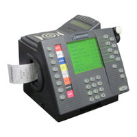
WAYFARER TGX150 Service Manual (126 pages)
INTERNAL RADIO LAN SMART CARD ELECTRONIC TICKET MACHINE
Brand:
WAYFARER
| Category:
Vending machines
| Size: 3 MB
Table of Contents
Table of Contents
3
About this Manual
7
Introduction
7
Purpose and Content of this Manual
7
Terms and Abbreviations Used in this Manual
9
Technical Data
11
General
11
Dimensions (Approximate)
11
Electrical
11
Environmental
11
General Description
13
What Is Radio Lan
13
What the Radio Lan System Does
13
Figure 1. the Radio LAN System
14
Physical Description
15
Detailed Description
16
Keyboard
16
Display
16
Printer and Paper Control Components
16
Memory Module Receptacle
17
ITSO Card Reader
17
Internal Radio LAN PCB Mount Assembly
17
Printed Circuit Boards
17
Model Identification
21
Figure 2A. Model and Serial Number Label
21
Installation
22
Installing the Ticket Machine
22
Fitting the Mounting Tray
23
Connecting the Power Cable Assembly
24
Figure 2B. Power, GPS, Serial no PCB, Connection Diagram
25
Final Operation
26
Maintenance & Repair - General Information
27
Precautions
27
Maintenance Levels
27
Tools and Equipment
28
Obtaining Spare Parts
29
Electronic Mail
29
Returning Machines or Assemblies for Repair
29
Routine Maintenance and Servicing
31
Maintenance Schedule
31
Exterior Cleaning
31
Display Cleaning
32
Lubrication
32
Interior Cleaning
32
Cleaning the Sync Sensor
32
Cleaning the Printer Roller
32
Cleaning the Print Head
33
Cleaning the Spigot (Shaft & Rotation Ball Bearing)
33
Servicing
34
Changing the Paper Roll
34
Figure 3. Paper Insertion Slot
34
Removing a Paper Blockage
35
Figure 4. Print Head Unlocking
35
Special Repair Operations
37
Connector Crimp Terminals
37
Figure 5. Connector Crimp Terminals
37
Removal and Replacement of Parts
39
Introduction
39
The Top Cover
40
Opening the Top Cover
40
Removing the Top Cover Stay
40
Figure 6. the Top Cover Stays
40
Removing the Top Cover
41
Figure 7. Top Cover Fixing Details
41
Removing the Top Inner Cover
42
Removing the Internal RLAN PCB Mount Assembly
42
Figure 8. Top Inner Cover Fixing Details
42
Figure 9A. RLAN & Contactless Reader Assembly Fixings
43
Figure 9B. Internal RLAN & Type A/B -2 Pcb's Mount Assembly
44
Removing the Contactless Reader Assembly
45
Figure 10. Contactless Reader Assembly
46
Keyboard and Display
47
Removing the Keyboard and Display Assembly
47
Figure 11. Keyboard and Display Fixings
47
Keyboard and Display Sub-Assemblies
48
Figure 12. Keyboard and Display Assembly Details
49
Printer Plate Assembly
51
Opening the Printer Plate Assembly
51
Removing the Printer Plate Assembly
51
Removing the Printer Mechanism
51
Removing the Printer Data Cable Assembly
52
Figure 13. Printer Base Assembly (1)
52
Removing the Top Cover Latching Hook
53
Removing the Sync Sensor and Bracket
53
Figure 14. Printer Plate Assembly (2)
53
Removing the Sync Wheel
54
Removing the Paper Roll Spigot
54
Figure 15. Paper Control Mechanism
54
Removing the Paper Roll Plinth
55
Dismantling the Printer Mechanism
55
Figure 16. Dismantling the Printer Mechanism
55
Figure 17. Printout Blade Fitting
56
Figure 18. Paper Guide Fitting
57
Figure 19. Section through Head Lock Knob
58
Figure 20. Print Roller and Motor Fitting
59
Figure 21. Print Head and Lower Paper Guide
60
Figure 22. Print Head Pivot Pins Location
61
Figure 23. Paper out Microswitch Fitting
62
The Module Housing Assembly
63
Figure 24. Module Housing Assembly to Control Board Fixings
63
Removal of Module Housing
64
Figure 25. Module Housing Assembly Exploded View
64
Module Housing Disassembly / Reassembly
65
Lower Cover
67
Removing the Lower Cover
67
Removing the Serial Number PCB
67
Removing the Type A/B-2 Coupler PCB
67
Removing the Memory Expansion & Internal Serial PCB
67
Removing the Control PCB
67
Figure 26. Control Board Fixings & Connections
68
Fault Finding and Testing
69
General Information
69
Types of Faults
72
Control Board Faults
72
Machine Dead
72
No Tickets Printed
72
Ticket Printing Uneven
73
Paper out Not Indicated
73
Paper Movement Faulty
74
Graphic Display Faulty
74
Repeater Display Faulty
75
Keys or Caption Strips Not Illuminated
76
Keys Inoperative
76
Memory Module Not Recognised
76
Difficulty in Inserting or Withdrawing a Module
77
ITSO Smart Card Not Accepted
77
No Radio LAN Comms
77
Testing and Repairing Cables Assemblies
78
Testing Cable Assemblies
78
Repairing Cable Assemblies
78
Figure 27. Crimp Pin Details
78
Figure 28. Interconnection Diagram
79
Figure 29. Printer Stepper Motor Drive Cable Assembly
80
Figure 30. Paper out Microswitch Cable Assembly
80
Figure 31. Printer Data Cable Assembly
81
Figure 32. Paper Movement Sensor Cable Assembly
81
Figure 33. Keyboard Power Cable Assembly
82
Figure 34. Keyboard Data Cable Assembly
83
Figure 35. Graphics Display Data Cable Assembly
84
Figure 36. Keyboard Backlighting Cable Assembly
85
Figure 37. Serial Number PCB Cable Assembly (if Fitted)
86
Figure 38. Solenoid (Module Housing) Cable Assembly (if Fitted)
87
Figure 39. Repeater Display Backlighting Cable Assembly 2
88
Figure 40. Repeater Display Backlighting Cable Assembly 1
88
Figure 41. Repeater Display Data Cable Assembly
89
Figure 42. ITSO RF Cable Assembly
90
Figure 43. ITSO Antenna LED Cable Assembly
90
Figure 44. Internal RLAN Cable Assembly
91
Figure 45. PWR+GPS+SERIAL Tray Cable Assembly
92
Drawings and Parts Lists
93
About the Assembly Drawings and Parts Lists
93
Sequence of Assembly Drawings and Parts Lists
93
Figure 46. General Assembly
94
Figure 47. Internal RLAN & Type A/B PCB Mount Assembly
97
Figure 48. Top Cover Assembly
98
Figure 49. Lower Cover Assembly
100
Figure 50. Printer Plate Assembly
102
Figure 51. Thermal Printer Assembly
104
Figure 52. Module Housing Assembly
107
Figure 53. Keyframe Assembly
109
Figure 54 Type A/B Card Reader Assembly
111
Figure 55. Mounting Tray Assembly - PWR+GPS+SN
113
Figure 56. Paper Ticket Punch Assembly (if Fitted)
115
Figure 57. Ticket Paper Specification
117
Parts Listing
118
58435 Label, Target
120
72776 Passenger Display Chassis
121
12037 Repeater Display 2 X
124
47113 Spacer, 6 Od 3.2 ID X 6 Long, Nylon
124
46664 Screw, M3 X 14, Pan Head, Pozi
124
46980 Screw, PT, 3 X 6 Lg, Pan Pozi
124
Appendix 1. Record of Amendments
126
Advertisement
WAYFARER TGX150 Training Manual (19 pages)
Cashier
Brand:
WAYFARER
| Category:
Payment Terminal
| Size: 0 MB
Table of Contents
Table of Contents
2
Introduction
3
Purpose
3
Scope
3
Audience
3
Related Documents
3
Document Revision History Summary
3
Glossary
4
Abbreviations
4
Terms
5
System Description
6
Overview
6
Cashier Functions
7
Sign-On
7
Cash-In Driver Scs
8
Driver Despatch
10
Cash-In Seller Scs
10
Seller Despatch
12
Supervisor Operations
13
Cashier Sign-Off with Sc
17
Different Cashier SC Sign-Off
18
Supervisor Sign-Off
18
Menu
19
Cashier Etm Function
19
Communication Trigger
19
Supervisor Menu
19
Advertisement
Related Products
WAYFARER Categories
Vending machines
Boat
Card Reader
Payment Terminal
More WAYFARER Manuals
Login
Sign In
OR
Sign in with Facebook
Sign in with Google
Upload manual
Upload from disk
Upload from URL