Sign In
Upload
Manuals
Brands
Watson-Marlow Manuals
Water Pump
qdos 60
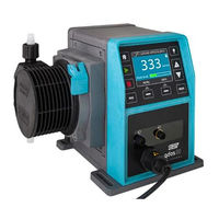
Watson-Marlow qdos 60 Metering Pump Manuals
Manuals and User Guides for Watson-Marlow qdos 60 Metering Pump. We have
2
Watson-Marlow qdos 60 Metering Pump manuals available for free PDF download: Reference Manual, Instructions For Use Manual
Watson-Marlow qdos 60 Reference Manual (331 pages)
pumps and accessories
Brand:
Watson-Marlow
| Category:
Water Pump
| Size: 15 MB
Table of Contents
Preface
2
Disclaimer
2
Translation of the Original Instructions
2
Trademarks
2
Table of Contents
3
Introduction to the Document
10
User Groups
10
Responsibility
10
Information Types
11
Qdos Range-Overview
12
Qdos Range-Introduction
12
Qdos Range-Terminology
13
Qdos Range-General Arrangement
14
Qdos Range-Intended Use
15
Prohibited Use
15
Safety
16
Safety Symbols
16
Instructions for Renewing Safety Symbols
16
Safety Alerts
17
Safety Alerts-With Risk of Personal Injury
17
Safety Alerts-With Risk of Equipment or Property Damage Only
18
Personal Protective Equipment (PPE)
18
Product Damage-Remove from Service
18
Flammable Liquids
19
Chemical Contact with Exterior Surfaces of the Product
19
Permeating Chemicals-Hose Connector Kit
20
Product Overview-Pump
21
Pump Models
21
Variations-Drive
22
General Arrangement-Drive
23
Product Marking-Drive
24
Variations-Pumphead
25
General Arrangement-Pumphead
27
General Arrangement-Pumphead Fluid Path Connections
28
Food and Beverage Applications-Pumphead
29
Product Marking-Pumphead
30
Product Code-Pumphead
31
Product Code-Pump
32
Specification-Pump
33
Performance
33
Maximum Inlet Pressure
33
Performance Curves
35
Physical Specification
38
Electrical Power Specification and Ratings
41
Control Specification
43
Start up Defaults
46
Control Panel Overview
47
Product Overview-Accessories
48
Accessories-Drive
48
Hydraulic Connectors
49
Hydraulic Connectors Supplied with Pump or Spare Drive
49
Accessory Hydraulic Connectors
50
Interface Tubing
51
Food and Beverage Applications-Accessories
52
Pressure Sensing Kit
53
Model Suitability-Pressure Sensing Kit
53
Features and Benefits-Pressure Sensing Kit
53
Intended Mounting-Pressure Sensing Kit
54
General Arrangement-Pressure Sensing Kit
55
Product Marking-Pressure Sensing Kit
58
Product Code-Pressure Sensing Kit
58
Required Pump Software Version for Use with a Pressure Sensing Kit
59
Control Settings Menu Overview-Pressure Sensing Kit
60
Defaults and Configurable Range
61
Screen Explanation and Action Due to Levels
62
Pressure Display on Home Screen
66
Ma Signal Versus Pressure
67
Pressure Sensing Kit Functions Not Available During Certain Operating Modes
68
Output of Pressure Alarms, Warnings and Signals
69
Disabling of a Pressure Sensing Kit
70
Specification
71
Hose Connector Kit
73
Model Suitability-Hose Connector Kit
73
Features and Benefits-Hose Connector Kit
73
Intended Mounting-Hose Connector Kit
73
General Arrangement-Hose Connector Kit
75
Product Marking-Hose Connector Kit
76
Product Code-Hose Connector Kit
77
Earth Bonding
77
Connecting Hoses Together
77
Specification
78
Storage
80
Storage Conditions
80
Shelf Life
80
Shelf Life-Pumphead
80
Shelf Life-Accessories
80
Lifting and Carrying
81
Product in Packaging
81
Procedure-Lifting and Carrying Product in Packaging
81
Product Removed from Packaging
81
Unpacking and Inspection
83
Components Supplied-Pump
83
Components Supplied-Replacement Pumphead
86
Components Supplied-Accessories
86
Components Supplied-Pressure Sensing Kit
86
Components Supplied-Hose Connector Kit
86
Unpacking, Inspection and Packaging Disposal
87
Installation-Chapter Overview
88
Using the HMI for Installation
88
1. Installation-Chapter 1: Location and Mounting
88
Conceptualisation
89
Environment and Operating Conditions
89
Intended Mounting Overview
91
Intended Mounting-Pump Overview
91
Intended Mounting-Pressure Sensing Kit
91
Intended Mounting-Hose Connector Kit
92
Intended Mounting-Pump
94
Area Around the Product-Not Enclosed
94
Surface and Orientation
97
Pump Mounting Dimensions
98
Procedure-Placing and Mounting the Pump
99
Mounting-Accessories
100
HMI Cover
100
Installation-Chapter 2 (Electrical Power)
101
Identification of Electrical Power Required
101
Alternating Current (AC) Power
101
Power Specification Requirements
101
Protection Device
101
Electrical Isolation
101
Cable (Wiring) Specification
102
Pre-Electrical Installation Requirement Checklist
103
Connect to AC Power Supply
103
Earth Continuity Testing Using the Earth Bond Test Point
104
Direct Current (DC) Power
105
Power Specification Requirements
105
Overcurrent Protection
105
Electrical Isolation
106
Power Cable (Wiring)
106
Pre-Electrical Installation Checklist
106
Connecting to a DC Power Supply
107
Testing of Electrical Power and First Time Pump Start up
107
Model: Remote
107
Model: Manual, PROFIBUS, Universal, Universal
107
Non-Return Valve
112
Input Connection
141
Output Connection
143
Control Cable Installation
150
PROFIBUS Connection
153
PROFIBUS Wiring
155
Analog 4-20 Ma Mode (Universal and Universal+ Only)
196
Manual Dosing
204
Calibrate the Pump for 4-20 Ma Control (Universal+ Only)
205
Assigning the PROFIBUS Station Address at the Pump
212
PROFIBUS Data Exchange
213
PROFIBUS GSD File
217
Channel-Related Diagnostic Data
219
Device-Related Diagnostic Data
219
User Parameter Data
220
Set Min/Max Speeds
220
Pre-Operation Check List
224
Maintenance
242
Periodic Inspection
243
Product End of Life
243
Software Update
245
Replacement Items
252
Replacement Spare Parts
280
Replacement of Fuses
282
Errors and Troubleshooting
284
Error Reporting
286
Leak Detection Procedure
288
Troubleshooting
289
Technical Support
291
Warranty
292
Chemical Compatibility
295
Materials of Construction
296
Product Recycling and Disposal
317
EU Declaration of Conformity
323
Standard Pump
331
Wet Location
331
Advertisement
Watson-Marlow qdos 60 Instructions For Use Manual (235 pages)
Brand:
Watson-Marlow
| Category:
Water Pump
| Size: 6 MB
Table of Contents
Preface
2
Disclaimer
2
Translation of the Original Instructions
2
Table of Contents
3
Introduction to the Document
11
User Groups
12
Information Types
12
Terminology
13
Trademarks
13
Acronyms
14
Introduction: Product
15
General Description
16
Intended Use
16
Prohibited Use
16
Safety
17
Safety Symbols
18
Instructions for Renewing Safety Symbols
18
Safety Signals
18
Signals: with Risk of Personal Injury
19
Signals: with Risk of Equipment or Property Damage Only
19
Personal Protective Equipment (PPE)
20
Product Overview
21
Pump Models
22
Drive-Variations
23
Drive-General Arrangement
24
Pumphead-Variations
25
Pumphead-General Arrangement
27
Pumphead-General Arrangement of Connections
28
Food Applications
29
Accessories
30
Product Labels
31
Product Code Guide
32
Specification Overview
33
Performance
33
Physical Specification
34
Electrical Power Specification
36
Control Specification
36
Storage
40
Storage Conditions
41
Shelf Life
41
Lifting and Carrying
42
Product Still in Original Packaging
43
Product Removed from Original Packaging
43
Unpacking Your Pump
44
Components Supplied with Your Pump
45
Unpacking, Inspection and Packaging Disposal
46
Installation Overview
47
Installation: Part 1 (Physical)
48
Conceptualisation
49
Location
49
Environmental and Operating Conditions
49
Area Around the Product-Not Enclosed
50
Mounting
51
Surface and Orientation
51
Anchorage (Bolting down the Pump)
53
HMI Cover
54
Other Accessories
54
Installation: Part 2 (Electrical Power)
55
Identification of Electrical Power Required
56
Alternating Current (AC) Power
56
Power Specification Requirements
56
Protection Device
57
Electrical Isolation
57
Cable (Wiring) Specification
57
Pre-Electrical Installation Requirement Checklist
58
Connect to AC Power Supply
58
Earth Continuity Testing Using the Earth Bond Test Point
59
Direct Current (DC) Power
59
Power Specification Requirements
59
Overcurrent Protection
60
Electrical Isolation
60
Power Cable (Wiring)
60
Pre-Electrical Installation Checklist
61
Connecting to a DC Power Supply
61
Testing of Electrical Power and First Time Pump Start up
61
Model: Remote
61
Model: Manual, PROFIBUS, Universal, Universal
61
Installation: Part 3 (Fluid Path)
62
Fluid Path System Requirements
63
Overpressure Safety Device
63
Non-Return Valve
63
Isolation and Drain Valves
64
Inlet and Discharge Pipework
64
Piping Vibration
64
Pre-Fluid Path Installation Requirement Checklist
65
Installing the Pumphead for the First Time
65
First Time Pumphead Installation: Qdos Renu 30: All Models Variants
66
First Time Pumphead Installation: (Qdos Renu 20, 60, 120 and Qdos CWT All Models Variants)
70
Connecting the Pumphead to the Fluid Path for the First Time
74
Step 1 Check the Seals in the Pumphead Ports
74
Step 3: Follow the Procedure for the Connector Type
74
Step 4: Connect the Pumphead Safety Overflow
74
Step 1 Check the Seals in the Pumphead Ports
75
Step 2: Choose the Connector Type to be Used
77
Step 3: Follow the Procedure for the Connector Type
79
Step 4: Connect the Pumphead Safety Overflow
83
Installation: Part 4 (Control Connections and Wiring)
84
Location of Connections
85
Front Input/Output Connections (Models: Remote, Universal, Universal+)
86
Input Connection
87
Relay Module-Option for Universal/Universal
92
Relay Module Specifications
92
Control Cable Specification Requirements
92
Relay Module PCB Layout
93
Relay Module Terminal Connectors
93
Control Cable Installation
96
PROFIBUS Connection
98
PROFIBUS Connection Pin Assignment
99
PROFIBUS Wiring
99
Pressure Sensor Control Connection (Models: PROFIBUS, Universal, Universal)
100
Installation: Part 5 (Setting up the Pump (General and Security))
101
General Settings (Models: Manual, PROFIBUS, Universal and Universal+)
102
GENERAL SETTINGS > Auto Restart
103
GENERAL SETTINGS > Flow Units
104
GENERAL SETTINGS > Asset Number
105
GENERAL SETTINGS > Pump Label
107
GENERAL SETTINGS > Language
109
Security Settings (Models: Manual, PROFIBUS, Universal and Universal+ Only)
111
Security Settings > Auto Keypad Lock
112
Security Settings > PIN Protection
114
Installation: Part 6 (Setting up the Pump (Control Settings))
117
Control Settings Menu
118
Control Settings > Speed Limit
119
Control Settings > Reset Run Hours
120
Control Settings > Reset Volume Counter
121
Control Settings > Invert Alarm Logic - Universal Model
121
Control Settings > Configurable Outputs - Universal+ Model
122
Control Settings 4-20 Ma Output (Universal+ Model Only)
124
Control Settings > Configurable Start/Stop Input
126
Control Settings Pumphead Selection
129
Change Mode (Manual, PROFIBUS, Universal and Universal+ Only)
129
PROFIBUS Mode
146
Setting PROFIBUS Mode
147
Assigning the PROFIBUS Station Address at the Pump
148
PROFIBUS Data Exchange
149
Cyclic Data Write (from Master to Pump)
150
Pumphead Speed Setpoint
150
Set Flow Calibration
150
Cyclic Data Read (from Pump to Master)
151
PROFIBUS GSD File
153
Channel-Related Diagnostic Data
155
Device-Related Diagnostic Data
155
User Parameter Data
156
Master Slave Communications Sequence
158
Operation
160
Pre-Operation Check List
161
Safety
162
Hazards that May Occur During Operation
162
Limits of Operation-Dry Running
163
Pump Operation (Models: Manual, PROFIBUS, Universal, Universal)
163
Switching Pump on in Subsequent Power Cycles (Models: Manual, PROFIBUS, Universal and Universal+)
163
Understanding and Using Menus and Modes
164
Using the Fluid Level Monitor (Models: Manual, PROFIBUS, Universal and Universal+)
166
Using Fluid Recovery Manual Operation (Manual, PROFIBUS, Universal and Universal+ Only)
170
Remote Fluid Recovery Using Analog Control (Remote, Universal and Universal+ Models Without Relay Modules)
173
Pump Status Overview
174
Screen Icons (Models: Manual, PROFIBUS, Universal, Universal+)
174
Front Cover Leds (Model: Remote)
175
Maintenance
177
Spare Parts
177
Electrical Maintenance
180
Drive Maintenance
180
Replacement of Power Cable
180
Replacement of Fuses
181
Pumphead Maintenance
181
Life of Pumphead
181
Replacement of Pumphead (Model: Qdos 30 - All Variants)
181
Replacement of Pumphead (Model Qdos 20, 60, 120, CWT - All Variants)
186
Errors, Breakdown and Troubleshooting
194
Errors
194
Remote Model
194
Manual, PROFIBUS, Universal, Universal+ Models
195
Error Reporting
195
Breakdown
196
Leak Detection Message (Models: Manual, PROFIBUS, Universal and Universal+ Models)
196
Leak Detection Message (Remote Only)
196
Leak Detection Procedure
197
Troubleshooting
198
Pumphead End of Life
198
Flowrate
198
Leak Detection Message
198
General Pump Help (Manual, PROFIBUS, Universal and Universal+ )
199
Technical Support
199
Manufacturer
199
Warranty
200
Conditions
200
Exceptions
200
Returning Pumps
201
Chemical Compatibility Overview
203
Chemical Compatibility
204
How to Check Chemical Compatibility
204
Scenario 1: Fluid Path (Wetted by the Pumped Fluid in Normal Use)
204
Scenario 2: Potential of Being Wetted Due to Environment or Spillage
207
Scenario 3: Potential of Being Wetted Due to Operating the Pumphead to the Point of Failure
208
Advertisement
Related Products
Watson-Marlow qdos30
Watson-Marlow qdos20
Watson-Marlow qdos60
Watson-Marlow qdos120
Watson-Marlow qdos 20
Watson-Marlow qdos 30
Watson-Marlow qdos 120
Watson-Marlow qdos CWT
Watson-Marlow qdos H-FLO
Watson-Marlow Qdos Pod
Watson-Marlow Categories
Water Pump
Power Pump
Control Unit
More Watson-Marlow Manuals
Login
Sign In
OR
Sign in with Facebook
Sign in with Google
Upload manual
Upload from disk
Upload from URL