Sign In
Upload
Manuals
Brands
WAGO Manuals
Control Unit
750-624/020-002
WAGO 750-624/020-002 Manuals
Manuals and User Guides for WAGO 750-624/020-002. We have
1
WAGO 750-624/020-002 manual available for free PDF download: Manual
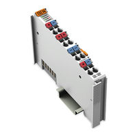
WAGO 750-624/020-002 Manual (60 pages)
Power Supply Filter 24 VDC HI GF; Higher Isolation; Ground Fault Diagnostics For WAGO-I/O-SYSTEM 750
Brand:
WAGO
| Category:
Water Filtration Systems
| Size: 3 MB
Table of Contents
Table of Contents
3
Notes about this Documentation
5
Validity of this Documentation
5
Copyright
5
Symbols
6
Number Notation
8
Font Conventions
8
Table 1: Number Notation
8
Table 2: Font Conventions
8
Important Notes
9
Legal Bases
9
Subject to Changes
9
Personnel Qualifications
9
Use of the 750 Series in Compliance with Underlying Provisions
9
Technical Condition of Specified Devices
10
Disposal
10
Electrical and Electronic Equipment
10
Packaging
11
Safety Advice (Precautions)
12
Device Description
15
Table 3: Compatibility List 750-626/020-002
16
View
17
Figure 1: View
17
Table 4: Legend for Figure "View
17
Connectors
18
Data Contacts/Local Bus
18
Figure 2: Data Contacts
18
Power Jumper Contacts/Field Supply
19
Figure 3: Power Jumper Contacts
19
Cage Clamp
20
Figure 4: CAGE CLAMP ® Connectors
20
Table 5: Legend for Figure "CAGE CLAMP ® Connectors
20
Display Elements
21
Operating Elements
21
Figure 5: Display Elements
21
Schematic Diagram
22
Figure 6: Schematic Diagram
22
Technical Data
23
Device Data
23
Power Supply
23
Ground Fault Diagnostics
23
Table 6: Technical Data - Device
23
Table 7: Technical Data - Power Supply
23
Table 8: Technical Data - Ground Fault Diagnostics
23
Communication
24
Connection Type
24
Table 9: Technical Data - Communication
24
Table 10: Technical Data - Field Wiring
24
Table 11: Technical Data - Power Jumper Contacts
24
Table 12: Technical Data - Data Contacts
24
Climate Environmental Conditions
25
Table 13: Technical Data - Climatic Environmental Conditions
25
Approvals
26
Standards and Guidelines
27
Mounting
28
Mounting Sequence
28
Inserting and Removing Devices
29
Inserting the I/O Module
29
Figure 7: Insert I/O Module (Example)
29
Figure 8: Snap the I/O Module into Place (Example)
29
Removing the I/O Module
30
Figure 9: Removing the I/O Module (Example)
30
Connect Devices
31
Connecting a Conductor to the CAGE CLAMP
31
Figure 10: Connecting a Conductor to a CAGE CLAMP
31
Ground Fault Diagnostics
32
Figure 11: Ground Fault Diagnostics Functionality
33
Process Image
34
Table 14: Internal Resistance (DC) of the Test Circuit and Threshold with Ground Fault
34
Table 15: Input Process Image
34
Table 16: Explanation of "Input Process Image
34
Wago-I/O-Check
35
Figure 12: WAGO-I/O-CHECK User Interface
35
Table 17: Output Process Image
35
Table 18: Explanation of "Output Process Image
35
Figure 13: WAGO-I/O-CHECK - Dialog Window
36
Figure 14: WAGO-I/O-CHECK - Ground Fault Diagnostics Dialog
36
Figure 15: WAGO-I/O-CHECK - Ground Fault Diagnostics Dialog
37
Figure 16: WAGO-I/O-CHECK - Ground Fault Diagnostics Dialog
37
Figure 17: WAGO-I/O-CHECK - Ground Fault Diagnostics Dialog
38
Figure 18: WAGO-I/O-CHECK - Disabling Ground Fault Diagnostics Dialog
38
Power Supply Concept for Marine Applications
39
Table 19: High-Isolation Filter Modules
39
Table 20: Explanation of the Table "High-Isolation Filter Modules
39
Figure 19: Power Supply Concept for Marine Applications - Class a and B
40
Table 21: Legend for Figure "Power Supply Concept for Marine Applications - Class a and B (Shown with 750-624/XXX-XXX for Field 2)
41
Table 22: Explanation of the Legend for Figure "Power Supply Concept for
41
Power Supply Concept for Marine Applications in Ex I
42
Figure 20: Power Supply Concept for Marine Applications in Ex I - Class a
42
Table 23: Legend for Figure "Power Supply Concept for Marine Applications in Ex I - Class a (Shown with 750-624/XXX-XXX for Field 2)
42
Figure 21: Power Supply Concept for Marine Applications in Ex I - Class B
43
Table 24: Explanation of the Legend for Figure "Power Supply Concept
43
Table 25: Legend for Figure "Power Supply Concept for Marine Applications in Ex I - Class B (Shown with 750-626/XXX-XXX for Field 2)
43
Table 26: Explanation of the Legend for Figure "Power Supply Concept
44
Use in Hazardous Environments
45
Marking Configuration Examples
46
Marking for Europe According to ATEX and Iecex
46
Figure 22: Marking Example According to ATEX and Iecex
46
Figure 23: Text Detail - Marking Example According to ATEX and Iecex
46
Table 27: Description of Marking Example According to ATEX and Iecex
47
Figure 24: Marking Example for Approved Ex I I/O Module According to ATEX
48
Figure 25: Text Detail - Marking Example for Approved Ex I I/O Module
48
Table 28: Description of Marking Example for Approved Ex I I/O Module According to ATEX and Iecex
49
Table 30: Description of Marking Example for Approved Ex I I/O Module
49
Marking for the United States of America (NEC) and Canada (CEC)50
50
Figure 26: Marking Example According to NEC
50
Figure 27: Text Detail - Marking Example According to NEC 500
50
Table 29: Description of Marking Example According to NEC 500
50
Figure 28: Text Detail - Marking Example for Approved Ex I I/O Module
51
Figure 29: Text Detail - Marking Example for Approved Ex I I/O Module
51
Table 31: Description of Marking Example for Approved Ex I I/O Modules
51
Figure 30: Text Detail - Marking Example for Approved Ex I I/O Modules
52
Table 32: Description of Marking Example for Approved Ex I I/O Modules
52
Installation Regulations
53
Special Notes Regarding Explosion Protection
53
Special Notes Regarding ANSI/ISA Ex
55
List of Figures
56
List of Tables
57
Advertisement
Advertisement
Related Products
WAGO 750-624/040-00 Series
WAGO 750-624/040-000
WAGO WAGO-I/O-SYSTEM 750-628
WAGO 750-626
WAGO 750-626/020-000
WAGO IO-Link Master 750-657
WAGO 750-637/000-002
WAGO 750-632/000-100
WAGO 750-606/040-000
WAGO 750-651/000-001
WAGO Categories
I/O Systems
Control Unit
Power Supply
Switch
Controller
More WAGO Manuals
Login
Sign In
OR
Sign in with Facebook
Sign in with Google
Upload manual
Upload from disk
Upload from URL