
Summary of Contents for WAGO 750-626/020-002
- Page 1 Manual WAGO-I/O-SYSTEM 750 750-626/020-002 Power Supply Filter 24 VDC HI GF Power Supply Filter (Surge); 24 VDC; Higher Isolation; Ground Fault Diagnostics Version 1.0.0...
- Page 2 WAGO-I/O-SYSTEM 750 750-626/020-002 Power Supply Filter 24 VDC HI GF © 2019 WAGO Kontakttechnik GmbH & Co. KG All rights reserved. WAGO Kontakttechnik GmbH & Co. KG Hansastraße 27 D-32423 Minden Phone: +49 (0) 571/8 87 – 0 Fax: +49 (0) 571/8 87 – 1 69 E-Mail: info@wago.com...
-
Page 3: Table Of Contents
WAGO-I/O-SYSTEM 750 Table of Contents 750-626/020-002 Power Supply Filter 24 VDC HI GF Table of Contents Notes about this Documentation ............. 5 Validity of this Documentation..............5 Copyright ....................5 Symbols ....................6 Number Notation ..................8 Font Conventions ................... 8 Important Notes .................. - Page 4 Table of Contents WAGO-I/O-SYSTEM 750 750-626/020-002 Power Supply Filter 24 VDC HI GF Power Supply Concept for Marine Applications ........39 6.3.1 Power Supply Concept for Marine Applications in Ex i ..... 42 Use in Hazardous Environments ............45 Marking Configuration Examples ............46 7.1.1...
-
Page 5: Notes About This Documentation
This documentation is only applicable to the I/O module 750-626/020-002 (Power Supply Filter 24 VDC HI GF). The I/O module 750-626/020-002 shall only be installed and operated according to the instructions in this manual and in the manual for the used fieldbus coupler or controller. -
Page 6: Symbols
Notes about this Documentation WAGO-I/O-SYSTEM 750 750-626/020-002 Power Supply Filter 24 VDC HI GF Symbols Personal Injury! Indicates a high-risk, imminently hazardous situation which, if not avoided, will result in death or serious injury. Personal Injury Caused by Electric Current! Indicates a high-risk, imminently hazardous situation which, if not avoided, will result in death or serious injury. - Page 7 WAGO-I/O-SYSTEM 750 Notes about this Documentation 750-626/020-002 Power Supply Filter 24 VDC HI GF Additional Information: Refers to additional information which is not an integral part of this documentation (e.g., the Internet). Manual Version 1.0.0...
-
Page 8: Number Notation
Notes about this Documentation WAGO-I/O-SYSTEM 750 750-626/020-002 Power Supply Filter 24 VDC HI GF Number Notation Table 1: Number Notation Number Code Example Note Decimal Normal notation Hexadecimal 0x64 C notation Binary '100' In quotation marks, nibble separated '0110.0100' with dots (.) -
Page 9: Important Notes
2.1.1 Subject to Changes WAGO Kontakttechnik GmbH & Co. KG reserves the right to provide for any alterations or modifications. WAGO Kontakttechnik GmbH & Co. KG owns all rights arising from the granting of patents or from the legal protection of utility patents. -
Page 10: Technical Condition Of Specified Devices
These modules contain no parts that can be serviced or repaired by the user. The following actions will result in the exclusion of liability on the part of WAGO Kontakttechnik GmbH & Co. KG: •... -
Page 11: Packaging
WAGO-I/O-SYSTEM 750 Important Notes 750-626/020-002 Power Supply Filter 24 VDC HI GF Environmentally friendly disposal benefits health and protects the environment from harmful substances in electrical and electronic equipment. • Observe national and local regulations for the disposal of electrical and electronic equipment. -
Page 12: Safety Advice (Precautions)
Important Notes WAGO-I/O-SYSTEM 750 750-626/020-002 Power Supply Filter 24 VDC HI GF Safety Advice (Precautions) For installing and operating purposes of the relevant device to your system the following safety precautions shall be observed: Do not work on devices while energized! All power sources to the device shall be switched off prior to performing any installation, repair or maintenance work. - Page 13 WAGO-I/O-SYSTEM 750 Important Notes 750-626/020-002 Power Supply Filter 24 VDC HI GF System supply only with appropriate fuse protection! Without overcurrent protection, the electronics can be damaged. For 24V system supply input voltage an external fuse, rated max. 2 A, slow acting, min.
- Page 14 Important Notes WAGO-I/O-SYSTEM 750 750-626/020-002 Power Supply Filter 24 VDC HI GF Replace defective or damaged devices! Replace defective or damaged device/module (e.g., in the event of deformed contacts). Protect the components against materials having seeping and insulating properties! The components are not resistant to materials having seeping and insulating properties such as: aerosols, silicones and triglycerides (found in some hand creams).
-
Page 15: Device Description
750-626/020-002 Power Supply Filter 24 VDC HI GF Device Description The power supply filter 750-626/020-002 (Power Supply Filter 24 VDC HI GF is used to feed the 24V system and 24V field supply voltage in a fieldbus node. It contains a filter for the 24V system supply as well as protection against transient overvoltages for the system supply and field supply via the power jumper contacts. -
Page 16: Table 3: Compatibility List 750-626/020-002
The field power supply also made available to the downstream I/O modules via the side power jumper contacts (spring contacts). The I/O-modul 750-626/020-002 can be operated on the listed fieldbus couplers and controllers of the 750 series from the specified version. -
Page 17: View
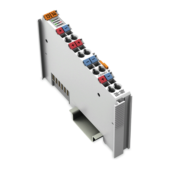
WAGO-I/O-SYSTEM 750 Device Description 750-626/020-002 Power Supply Filter 24 VDC HI GF View Figure 1: View Table 4: Legend for Figure “View” Pos. Description Details See Section Marking possibility with Mini- Status LEDs “Device Description” > “Display Elements” Data contacts “Device Description”... -
Page 18: Connectors
Device Description WAGO-I/O-SYSTEM 750 750-626/020-002 Power Supply Filter 24 VDC HI GF Connectors 3.2.1 Data Contacts/Local Bus Communication between the fieldbus coupler, controller and the I/O modules as well as the system supply of the I/O modules is carried out via the local bus. The contacting for the local bus consists of 6 data contacts, which are available as self-cleaning gold spring contacts. -
Page 19: Power Jumper Contacts/Field Supply
750-626/020-002 Power Supply Filter 24 VDC HI GF 3.2.2 Power Jumper Contacts/Field Supply The power supply filter 750-626/020-002 has 2 self-cleaning power jumper contacts that transmit power for the field side. The contacts on the right side of the power supply filter are designed as spring contacts. -
Page 20: Cage Clamp
Device Description WAGO-I/O-SYSTEM 750 750-626/020-002 Power Supply Filter 24 VDC HI GF ® 3.2.3 CAGE CLAMP Connectors ® Figure 4: CAGE CLAMP Connectors ® Table 5: Legend for Figure “CAGE CLAMP Connectors” Designation Connector Function +24V-System OUT 1 Output system supply 24 VDC (filtered) -
Page 21: Display Elements
No 24 VDC voltage supply via power jumper contacts Status 24V-Field 24 VDC voltage supply via power Green jumper contacts No ground fault detected. Ground fault Ground fault detected. Operating Elements The power supply filter 750-626/020-002 has no operating elements. Manual Version 1.0.0... -
Page 22: Schematic Diagram
Device Description WAGO-I/O-SYSTEM 750 750-626/020-002 Power Supply Filter 24 VDC HI GF Schematic Diagram Figure 6: Schematic diagram Manual Version 1.0.0... -
Page 23: Technical Data
WAGO-I/O-SYSTEM 750 Device Description 750-626/020-002 Power Supply Filter 24 VDC HI GF Technical Data 3.6.1 Device Data Table 6: Technical Data — Device Width 12 mm Height (from upper edge of DIN-rail) 64 mm Depth 100 mm Weight 53 g 3.6.2... -
Page 24: Communication
Device Description WAGO-I/O-SYSTEM 750 750-626/020-002 Power Supply Filter 24 VDC HI GF 3.6.4 Communication Table 9: Technical Data – Communication Data width (local bus) 8-bit input intern 8-bit output 3.6.5 Connection Type Table 10: Technical Data – Field Wiring ®... -
Page 25: Climate Environmental Conditions
WAGO-I/O-SYSTEM 750 Device Description 750-626/020-002 Power Supply Filter 24 VDC HI GF 3.6.6 Climate Environmental Conditions Table 13: Technical Data ‒ Climatic Environmental Conditions Surrounding air temperature, operation 0 °… 55 °C Surrounding air temperature, storage −25 °… +85 °C Relative humidity (without Max. -
Page 26: Approvals
Approvals More information about approvals. Detailed references to the approvals are listed in the document “Overview Approvals WAGO-I/O-SYSTEM 750”, which you can find via the internet under: www.wago.com DOWNLOADS Documentation System Description. The following approval has been granted to 750-626/020-002 I/O modules:... -
Page 27: Standards And Guidelines
WAGO-I/O-SYSTEM 750 Device Description 750-626/020-002 Power Supply Filter 24 VDC HI GF Standards and Guidelines 750-626/020-002 I/O modules meet the following requirements on emission and immunity of interference: EU EMC Directive 2014/30/EU EMC CE-Emission of interference EN 61000-6-3 EMC CE-Immunity to interference... -
Page 28: Mounting
Don't forget the bus end module! Always plug a bus end module (750-600) onto the end of the fieldbus node! You must always use a bus end module at all fieldbus nodes with WAGO-I/O- SYSTEM 750 fieldbus couplers or controllers to guarantee proper data transfer. -
Page 29: Inserting And Removing Devices
WAGO-I/O-SYSTEM 750 Mounting 750-626/020-002 Power Supply Filter 24 VDC HI GF Inserting and Removing Devices Do not work when devices are energized! High voltage can cause electric shock or burns. Switch off all power to the device prior to performing any installation, repair or maintenance work. -
Page 30: Removing The I/O Module
Mounting WAGO-I/O-SYSTEM 750 750-626/020-002 Power Supply Filter 24 VDC HI GF 4.2.2 Removing the I/O Module Remove the I/O module from the assembly by pulling the release tab. Figure 9: Removing the I/O Module (Example) Electrical connections for data or power jumper contacts are disconnected when removing the I/O module. -
Page 31: Connect Devices
Only one conductor may be connected to each CAGE CLAMP Do not connect more than one conductor at one single connection! If more than one conductor must be routed to one connection, these must be connected in an up-circuit wiring assembly, for example using WAGO feed- through terminals. ®... -
Page 32: Ground Fault Diagnostics
Ground Fault Diagnostics WAGO-I/O-SYSTEM 750 750-626/020-002 Power Supply Filter 24 VDC HI GF Ground Fault Diagnostics Faulty ground fault diagnostics! Ground fault diagnostics is (functional) not possible or only partially possible: • Superimposed DC external voltage between the 24V field and ground potential •... -
Page 33: Figure 11: Ground Fault Diagnostics Functionality
The user must set the “GFT” (Ground Fault Test) bit in the output process image of the fieldbus coupler or controller. The field bus, PLC application or WAGO-I/O-CHECK commissioning tool can be used for this purpose. Connecting the ground fault diagnostics influences measurement of a ground... -
Page 34: Process Image
Ground Fault Diagnostics WAGO-I/O-SYSTEM 750 750-626/020-002 Power Supply Filter 24 VDC HI GF Table 14: Internal Resistance (DC) of the Test Circuit and Threshold with Ground Fault Operating Internal Thresholds with State Module Resistance (DC) Ground Fault (System, Ship) Test Circuit Ground diagnostics Normal operation >10 MΩ... -
Page 35: Wago-I/O-Check
Not used WAGO-I/O-CHECK Information WAGO-I/O-CHECK Compatibility. The 750-626/020-002 filter module is supported by the WAGO-I/O-CHECK commissioning tool, version 3.19.2 (02) or higher. Enable: 1. Open WAGO-I/O-CHECK. 2. Click the [Identify] button. Figure 12: WAGO-I/O-CHECK User Interface 3. -
Page 36: Figure 13: Wago-I/O-Check - Dialog Window
Ground Fault Diagnostics WAGO-I/O-SYSTEM 750 750-626/020-002 Power Supply Filter 24 VDC HI GF A dialog window opens. Figure 13: WAGO-I/O-CHECK – Dialog Window The Field Voltage field indicates whether the field voltage is present. • Field voltage available: Requirement for ground fault diagnostics •... -
Page 37: Figure 15: Wago-I/O-Check - Ground Fault Diagnostics Dialog
WAGO-I/O-SYSTEM 750 Ground Fault Diagnostics 750-626/020-002 Power Supply Filter 24 VDC HI GF Figure 15: WAGO-I/O-CHECK – Ground Fault Diagnostics Dialog, Diagnostics Enabled Ground fault diagnostics is enabled. Note Changes possible during ground fault diagnostics! Enabled ground fault diagnostics is indicated as follows: •... -
Page 38: Figure 17: Wago-I/O-Check - Ground Fault Diagnostics Dialog
Ground Fault Diagnostics WAGO-I/O-SYSTEM 750 750-626/020-002 Power Supply Filter 24 VDC HI GF Figure 17: WAGO-I/O-CHECK – Ground Fault Diagnostics Dialog, Main Alarm 0V Disable: If ground fault diagnostics is disabled, the internal test circuit is separated from the ground potential with high resistance. -
Page 39: Power Supply Concept For Marine Applications
Filter module, 24 VDC, HI, with ground fault diagnostics (750-624/020-002) Filter module, 24 VDC, HI (750-626/020-000) Power supply filter Filter module, 24 VDC, HI, with ground fault diagnostics (750-626/020-002) Filter module, 24 VDC, HI / T (750-626/025-001) Table 20: Explanation of the Table “High-Isolation Filter Modules”... -
Page 40: Figure 19: Power Supply Concept For Marine Applications - Class A And B
Observe the data sheets of the individual I/O modules. The following shows the power supply concept of a fieldbus node of the WAGO- I/O-SYSTEM 750 for certified use in shipping. Power Supply Concept for Marine Applications – Class A and B Figure 19: Power Supply Concept for Marine Applications –... -
Page 41: Table 21: Legend For Figure "Power Supply Concept For Marine Applications - Class A And B (Shown With 750-624/Xxx-Xxx For Field 2)
WAGO-I/O-SYSTEM 750 Ground Fault Diagnostics 750-626/020-002 Power Supply Filter 24 VDC HI GF Table 21: Legend for Figure “Power Supply Concept for Marine Applications – Class A and B (shown with 750-624/xxx-xxx for Field 2)” Explanation Fieldbus Couplers/Controllers Filter module, 24 VDC, HI GF (750-626/020-002) or... -
Page 42: Power Supply Concept For Marine Applications In Ex I
Ground Fault Diagnostics WAGO-I/O-SYSTEM 750 750-626/020-002 Power Supply Filter 24 VDC HI GF 6.3.1 Power Supply Concept for Marine Applications in Ex i Use the appropriate filter module in marine applications! Power to the Ex i supply module is supplied via the appropriate filter module... -
Page 43: Figure 21: Power Supply Concept For Marine Applications In Ex I - Class B
WAGO-I/O-SYSTEM 750 Ground Fault Diagnostics 750-626/020-002 Power Supply Filter 24 VDC HI GF Table 24: Explanation of the Legend for figure “Power Supply Concept for Marine Applications in Ex i – Class A (shown with 750-624/xxx-xxx for Field 2)” Explanation... -
Page 44: Table 26: Explanation Of The Legend For Figure "Power Supply Concept
Ground Fault Diagnostics WAGO-I/O-SYSTEM 750 750-626/020-002 Power Supply Filter 24 VDC HI GF Table 26: Explanation of the Legend for figure “Power Supply Concept for Marine Applications in Ex i – Class B (shown with 750-626/xxx-xxx for Field 2)” Explanation... -
Page 45: Use In Hazardous Environments
Use in Hazardous Environments 750-626/020-002 Power Supply Filter 24 VDC HI GF Use in Hazardous Environments The WAGO-I/O-SYSTEM 750 (electrical equipment) is designed for use in Zone 2 hazardous areas and shall be used in accordance with the marking and installation regulations. -
Page 46: Marking Configuration Examples
Use in Hazardous Environments WAGO-I/O-SYSTEM 750 750-626/020-002 Power Supply Filter 24 VDC HI GF Marking Configuration Examples 7.1.1 Marking for Europe According to ATEX and IECEx Figure 22: Marking Example According to ATEX and IECEx Figure 23: Text Detail – Marking Example According to ATEX and IECEx Manual Version 1.0.0... -
Page 47: Table 27: Description Of Marking Example According To Atex And Iecex
WAGO-I/O-SYSTEM 750 Use in Hazardous Environments 750-626/020-002 Power Supply Filter 24 VDC HI GF Table 27: Description of Marking Example According to ATEX and IECEx Marking Description TUEV 07 ATEX 554086 X Approving authority resp. certificate numbers IECEx TUN 09.0001 X... -
Page 48: Figure 24: Marking Example For Approved Ex I I/O Module According To Atex
Use in Hazardous Environments WAGO-I/O-SYSTEM 750 750-626/020-002 Power Supply Filter 24 VDC HI GF Figure 24: Marking Example for Approved Ex i I/O Module According to ATEX and IECEx Figure 25: Text Detail – Marking Example for Approved Ex i I/O Module According to ATEX and... -
Page 49: Table 28: Description Of Marking Example For Approved Ex I I/O Module According To Atex And Iecex
WAGO-I/O-SYSTEM 750 Use in Hazardous Environments 750-626/020-002 Power Supply Filter 24 VDC HI GF Table 28: Description of Marking Example for Approved Ex i I/O Module According to ATEX and IECEx Marking Description TUEV 12 ATEX 106032 X Approving authority resp. certificate numbers... -
Page 50: Marking For The United States Of America (Nec) And Canada (Cec)50
Use in Hazardous Environments WAGO-I/O-SYSTEM 750 750-626/020-002 Power Supply Filter 24 VDC HI GF 7.1.2 Marking for the United States of America (NEC) and Canada (CEC) Figure 26: Marking Example According to NEC Figure 27: Text Detail – Marking Example According to NEC 500... -
Page 51: Figure 28: Text Detail - Marking Example For Approved Ex I I/O Module
WAGO-I/O-SYSTEM 750 Use in Hazardous Environments 750-626/020-002 Power Supply Filter 24 VDC HI GF Figure 28: Text Detail – Marking Example for Approved Ex i I/O Module According to NEC 505 Table 30: Description of Marking Example for Approved Ex i I/O Module According to NEC 505... -
Page 52: Figure 30: Text Detail - Marking Example For Approved Ex I I/O Modules
Use in Hazardous Environments WAGO-I/O-SYSTEM 750 750-626/020-002 Power Supply Filter 24 VDC HI GF Figure 30: Text Detail – Marking Example for Approved Ex i I/O Modules According to CEC 18 attachment J Table 32: Description of Marking Example for Approved Ex i I/O Modules According to CEC 18... -
Page 53: Installation Regulations
WAGO-I/O-SYSTEM 750 Use in Hazardous Environments 750-626/020-002 Power Supply Filter 24 VDC HI GF Installation Regulations For the installation and operation of electrical equipment in hazardous areas, the valid national and international rules and regulations which are applicable at the installation location must be carefully followed. - Page 54 Use in Hazardous Environments WAGO-I/O-SYSTEM 750 750-626/020-002 Power Supply Filter 24 VDC HI GF Explosive atmosphere occurring simultaneously with assembly, installation or repair work must be ruled out. Among other things, these include the following activities • Insertion and removal of components •...
-
Page 55: Special Notes Regarding Ansi/Isa Ex
WAGO-I/O-SYSTEM 750 Use in Hazardous Environments 750-626/020-002 Power Supply Filter 24 VDC HI GF 7.2.2 Special Notes Regarding ANSI/ISA Ex For ANSI/ISA Ex acc. to UL File E198726, the following additional requirements apply: • Use in Class I, Division 2, Group A, B, C, D or non-hazardous areas only •... -
Page 56: List Of Figures
Figure 17: WAGO-I/O-CHECK – Ground Fault Diagnostics Dialog, Main Alarm 0V ..................38 Figure 18: WAGO-I/O-CHECK – Disabling Ground Fault Diagnostics Dialog ..38 Figure 19: Power Supply Concept for Marine Applications – Class A and B (shown with 750-624/xxx-xxx for Field 2) ..........40 Figure 20: Power Supply Concept for Marine Applications in Ex i –... -
Page 57: List Of Tables
WAGO-I/O-SYSTEM 750 List of Tables 750-626/020-002 Power Supply Filter 24 VDC HI GF List of Tables Table 1: Number Notation ................... 8 Table 2: Font Conventions .................. 8 Table 3: Compatibility List 750-626/020-002 ............16 Table 4: Legend for Figure “View” ..............17 ®... - Page 58 List of Tables WAGO-I/O-SYSTEM 750 750-626/020-002 Power Supply Filter 24 VDC HI GF Manual Version 1.0.0...
- Page 59 WAGO-I/O-SYSTEM 750 750-626/020-002 Power Supply Filter 24 VDC HI GF Manual Version 1.0.0...
- Page 60 WAGO Kontakttechnik GmbH & Co. KG Postfach 2880 • D - 32385 Minden Hansastraße 27 • D - 32423 Minden Phone: +49 571 887 – 0 Fax: +49 571 887 – 844169 E-Mail: info@wago.com Internet: www.wago.com...
Need help?
Do you have a question about the 750-626/020-002 and is the answer not in the manual?
Questions and answers