Sign In
Upload
Manuals
Brands
Victron energy Manuals
Controller
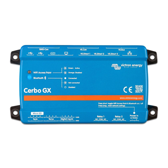
Cerbo GX
User Manuals: Victron energy Cerbo GX Centre
Manuals and User Guides for Victron energy Cerbo GX Centre. We have
6
Victron energy Cerbo GX Centre manuals available for free PDF download: Manual, Instructions Manual
Victron energy Cerbo GX Manual (131 pages)
Brand:
Victron energy
| Category:
Control Unit
| Size: 19 MB
Table of Contents
Table of Contents
2
Safety Instructions
7
Introduction
8
What Is the Color Control GX
8
What's in the Box
8
Installation
9
Color Control GX Overview of Connections
9
Mounting Options and Accessories
10
Powering the Color Control GX
11
Snap-On Ferrite Beads for Class B EMI Compliance
11
Relay Connections
13
Connecting Victron Products
14
Ve.bus Multis/Quattros/Inverters
14
AC Load Monitoring
15
Battery Monitor Smartshunt, BMV-700 Series; and Mppts with a Ve.direct Port
15
DC Load Monitor Mode
16
Ve.can Devices
17
Ve.can Interfaces
17
Inverter RS, Multi RS and MPPT RS
17
Series
17
DC Link Box
18
Ve.can Resistive Tank Sender Adapter
18
Connecting a GX Tank 140
18
Connecting Supported Non-Victron Products
19
Connecting a PV Inverter
19
Connecting a USB GPS
19
Connecting a NMEA 2000 GPS
20
Connecting a Fischer Panda Generator
20
Connecting Third-Party NMEA 2000 Tank Senders
20
Mopeka Pro Check LPG and Water Bluetooth Sensors
22
Installation
22
Configuration
23
Tank Level Monitoring
24
Wakespeed WS500 Alternator Regulator Support
25
Introduction
25
Requirements
25
Wiring the WS500 to Ve.can
25
Wiring Example
26
GX Device User Interface for WS500
27
WS500 Data on the VRM Portal
27
Troubleshooting & FAQ
28
Wireless Bluetooth Ruuvi Temperature Sensors
29
Connecting IMT Solar Irradiance, Temperature and Wind Speed Sensors
31
Data Visualisation - VRM
34
Internet Connectivity
35
Ethernet LAN Port
35
Wifi
36
Gx Lte 4G
36
Mobile (Cellular) Network Using a 3G or 4G Router
36
USB Tethering Using a Mobile Phone
37
Manual IP Configuration
37
Connecting both Ethernet and Wifi (Failover)
37
Minimise Internet Traffic
37
More Information about Setting up an Internet Connection and VRM
38
Accessing the GX Device
39
Accessing the Remote Console Via Local Lan/Wifi Network
40
Alternative Methods to Find the IP Address for Remote Console
40
Accessing Via VRM
41
The Remote Console Menu
42
Configuration
43
Menu Structure and Configurable Parameters
43
Battery State of Charge (Soc)
50
Which Device Should I Use for Soc Calculation
50
The Different Solutions Explained in Detail
50
Notes on Soc
51
Selecting Soc Source
51
Details on Ve.bus SOC
52
The System Status Menu
52
Customise the Logo on the Boat & Motorhome Page
53
Temperature Relay Configuration
54
Firmware Updates
56
Changelog
56
Updating from Version 1.X to 2
56
Via Internet or with Microsd-Card/Usb-Stick
56
Direct Download from the Internet
56
Microsd-Card or USB-Stick
57
Revert to a Previous Firmware Version
57
Stored Firmware Backup Feature
58
Install a Specific Firmware Version from SD/USB
59
Ve.bus Inverter/Charger Monitoring
60
Input Current-Limiter Setting
60
Phase Rotation Warning
61
Grid Failure Monitoring
62
Advanced Menu
62
Alarm Status Monitoring
63
Ve.bus Alarm Setup Menu
63
Device Menu
63
DVCC - Distributed Voltage and Current Control
64
Introduction and Features
64
DVCC Requirements
65
DVCC Effects on the Charge Algorithm
66
DVCC Effects When There Is more than One Multi/Quattro Connected
66
DVCC Features for All Systems
67
Limit Charge Current
67
Limit Managed Battery Charge Voltage
67
Shared Voltage Sense (SVS)
68
Shared Temperature Sense (STS)
68
Shared Current Sense (SCS)
69
Controlling BMS
69
DVCC Features When Using CAN-Bus BMS Battery
70
DVCC for Systems with the ESS Assistant
71
VRM Portal
72
VRM Portal Introduction
72
Registering on VRM
72
Datalogging to VRM
72
Troubleshooting Data Logging
74
Analysing Data Offline, Without VRM
76
Remote Console on VRM - Setup
77
Remote Console on VRM - Troubleshooting
77
Marine MFD Integration by App
79
Introduction & Requirements
79
Compatible Mfds and Instructions
80
Raymarine MFD Integration
80
Introduction
80
Compatibility
80
Wiring
80
GX Device Configuration
81
Configuring Multiple Battery Measurements
81
Installation Step-By-Step
81
Nmea 2000
82
Generic and Supported
82
Instancing Requirements When Using Raymarine
82
Before Lighthouse 4.1.75
82
Lighthouse 4.1.75 and Newer
83
Navico MFD Integration
83
Introduction
83
Compatibility
83
Wiring
84
GX Device Configuration
84
Configuring Multiple Battery Measurements
84
Installation Step-By-Step
85
Nmea 2000
85
Generic and Supported
85
Troubleshooting
86
Garmin MFD Integration
86
Introduction
86
Compatibility
86
Wiring
86
GX Device Configuration
87
Configuring Multiple Battery Measurements
87
Installation Step-By-Step
88
Nmea 2000
88
Generic and Supported
88
Furuno MFD Integration
89
Introduction
89
Compatibility
89
Wiring
89
Configuration
89
Configuring Multiple Battery Measurements
90
Nmea 2000
90
Generic and Supported
91
Marine MFD Integration by NMEA 2000
92
NMEA 2000 Introduction
92
Supported Devices
92
NMEA 2000 Configuration
94
Configuration of Multiple Tank Level Measurements Via NMEA2000-Out for Raymarine Mfds
94
Configuration of Multiple Tank Level Measurements Via NMEA2000-Out for Garmin Mfds
95
Configuration of Multiple Tank Level Measurements Via NMEA2000-Out for Navico Mfds
96
Configuration of Multiple Tank Level Measurements Via NMEA2000-Out for Furuno Mfds
98
NMEA 2000 Configuring Device Instances
98
NMEA2000-Out Technical Details
99
NMEA 2000 Glossary
99
NMEA 2000 Virtual-Devices
99
NMEA 2000 Classes and Functions
99
NMEA 2000 Instances
100
NMEA 2000 Changing Instances
101
PGN 60928 NAME Unique Identity Numbers
101
RV-C Support
102
RV-C Introduction
102
Limitations
102
Supported Devices
102
RV-C Configuration
103
Configuration of RV-C out Devices
104
Garnet Seelevel II 709-RVC & Victron GX Device Support
105
Wiring the Garnet Seelevel II 709-RVC Tank Level Sensor to a GX Device
105
Installation and Configuration
105
GX - Generator Auto Start/Stop
106
Generator Auto Start/Stop Introduction
106
Wiring
106
Enabling the Start/Stop Function
106
General Start/Stop Menu
107
Settings Menu
107
Conditions: User Definable Parameters that Trigger an Automatic Generator Start/Stop
108
Generator Stop When AC-Input Becomes Available after a Mains Failure
108
Relays Triggered by Battery Soc
108
Relays Triggered by Battery Current
109
Relays Triggered by Battery Voltage
109
Relays Triggered by AC Load
109
Relays Triggered by Inverter High Temperature
110
Relays Triggered by Inverter Overload
110
Automatic Periodic 'Test Run
110
Manual Start Feature
110
Quiet Hours
111
Troubleshooting
112
Reset to Factory Defaults Procedure
113
Troubleshooting
114
Error Codes
114
Faq
115
Q1: I Cannot Switch My Multi/Quattro System on or off
115
Q2: Do I Need a BMV to See Proper Battery State of Charge
115
Q3: I Have no Internet, Where Can I Insert a SIM Card
115
Q4: Can I Connect both a GX Device and a VGR2/VER to a Multi/Inverter/Quattro
115
Q5: Can I Connect Multiple Color Control GX to a Multi/Inverter/Quattro
115
Q6: I See Incorrect Current (Amps) or Power Readings on My CCGX
116
Q7: There Is a Menu Entry Named "Multi" Instead of the Ve.bus Product Name
116
Q8: There Is a Menu Entry Named "Multi", While There Is no Inverter, Multi or Quattro Connected
116
Q9: When I Type the IP Address of the Color Control GX into My Browser, I See a Web Page Mentioning Hiawatha
117
Q10: I Have Multiple Solar Chargers MPPT 150/70 Running in Parallel. from Which One will I See the Relay Status in the CCGX Menu
117
Q11: How Long Should an Automatic Update Take
117
Q12: I Have a VGR with IO Extender, How Can I Replace this with a Color Control GX
117
Q13: Can I Use Remote Veconfigure, as I was Doing with the VGR2
117
Q14: the Blue Power Panel Could be Powered through the Ve.net Network, Can I also Do that with a Color Control GX
117
Q15: What Type of Networking Is Used by the Color Control GX (TCP and UDP Ports)
117
Q16: What Is the Functionality Behind the Menu Item Remote Support (SSH) in the Ethernet Menu
118
Q17: I Don't See Support for Ve.net Products in the List, Is that Still Coming
118
Q18: What Is the Data Usage of the Color Control GX
118
Q19: How Many AC Current Sensors Can I Connect in One Ve.bus System
118
Q20: Issues with Multi Not Starting When CCGX Is Connected / Caution When Powering the CCGX from the AC-Out Terminal of a Ve.bus Inverter, Multi or Quattro
118
Q21: I Love Linux, Programming, Victron and the CCGX. Can I Do more
119
Q22: How Do I Change the Logo
119
Q23: Multi Restarts All the Time (after Every 10Sec)
119
Q24: What Is Error #42
119
Q25: My GX Device Reboots Itself. What Is Causing this Behavior
119
GPL Note
120
Technical Specifications
121
Appendix
122
Rv-C
122
Supported Dgns
122
RV-C out
122
DGN 60928 Unique Identity Numbers
128
RV-C in
128
Device Classes
128
Instance Translation
129
RV-C Fault and Error Handling
129
Advertisement
Victron energy Cerbo GX Manual (92 pages)
Brand:
Victron energy
| Category:
Controller
| Size: 9 MB
Table of Contents
Table of Contents
2
Safety Instructions
7
Introduction
8
What Is the Cerbo GX
8
What's in the Box
8
Installation
9
Cerbo GX Overview of Connections
9
Mounting Options and Accessories
10
Powering the Cerbo GX
11
GX Touch 50 & GX Touch 70
12
Deactivating Touch Input Control
14
Relay Connections
15
Connecting Victron Products
16
Ve.bus Multis/Quattros/Inverters
16
AC Load Monitoring
17
Battery Monitor Smartshunt, BMV-700 Series; and Mppts with a Ve.direct Port
17
DC Load Monitor Mode
18
Ve.can Devices
19
Ve.can and BMS-Can Interfaces
19
Inverter RS, Multi RS and MPPT RS
20
BMV-600 Series
20
DC Link Box
20
Ve.can Resistive Tank Sender Adapter
20
Connecting a GX Tank 140
20
Connecting Hardwired Victron Temperature Sensors
21
Connecting Supported Non-Victron Products
22
Connecting a PV Inverter
22
Connecting a USB GPS
22
Connecting a NMEA 2000 GPS
23
Connecting a Fischer Panda Generator
23
Connecting Tank Level Sensors to the GX Tank Inputs
24
Increasing the Number of Tank Inputs by Using Multiple GX Devices
25
Introduction
25
Requirements
26
Configuration Step-By-Step
26
Connecting Third-Party NMEA 2000 Tank Senders
27
Mopeka Pro Check LPG and Water Bluetooth Sensors
28
Installation
28
Configuration
29
Tank Level Monitoring
30
Wakespeed WS500 Alternator Regulator Support
31
Introduction
31
Requirements
31
Wiring the WS500 to Ve.can
31
Wiring Example
32
GX Device User Interface for WS500
33
WS500 Data on the VRM Portal
33
Troubleshooting & FAQ
34
Wireless Bluetooth Ruuvi Temperature Sensors
35
Connecting IMT Solar Irradiance, Temperature and Wind Speed Sensors
37
Data Visualisation - VRM
40
Connecting a Comap CM-Ethernet Module
40
Introduction
40
Installation & Configuration
41
Internet Connectivity
43
Ethernet LAN Port
43
Wifi
44
Gx Lte 4G
44
Mobile (Cellular) Network Using a 3G or 4G Router
44
USB Tethering Using a Mobile Phone
45
Manual IP Configuration
45
Multiple Connections (Failover)
45
Minimise Internet Traffic
45
More Information about Setting up an Internet Connection and VRM
47
Accessing the GX Device
48
Using Victronconnect Via Bluetooth
49
Accessing Via Built-In Wifi Access Point
50
Accessing the Remote Console Via Local Lan/Wifi Network
51
Alternative Methods to Find the IP Address for Remote Console
51
Accessing Via VRM
52
The Remote Console Menu
53
Configuration
54
Menu Structure and Configurable Parameters
54
Battery State of Charge (Soc)
62
Which Device Should I Use for Soc Calculation
62
The Different Solutions Explained in Detail
62
Notes on Soc
63
Selecting Soc Source
63
Details on Ve.bus SOC
64
The System Status Menu
64
Customise the Logo on the Boat & Motorhome Page
65
Leds and Push-Button
65
Leds
65
Small Recessed Button above the Power in Terminal Block
65
Temperature Relay Configuration
66
Firmware Updates
68
Changelog
68
Via Internet or with Microsd-Card/Usb-Stick
68
Direct Download from the Internet
68
Microsd-Card or USB-Stick
69
Revert to a Previous Firmware Version
69
Stored Firmware Backup Feature
70
Install a Specific Firmware Version from SD/USB
71
Venus os Large Image
71
Ve.bus Inverter/Charger Monitoring
72
Input Current-Limiter Setting
72
Phase Rotation Warning
73
BMS Connection Lost Alarm
73
Grid Failure Monitoring
74
Advanced Menu
74
Alarm Status Monitoring
75
Ve.bus Alarm Setup Menu
75
Device Menu
75
Solar & Wind Priority
76
DVCC - Distributed Voltage and Current Control
77
Introduction and Features
77
DVCC Requirements
78
DVCC Effects on the Charge Algorithm
79
DVCC Effects When There Is more than One Multi/Quattro Connected
79
DVCC Features for All Systems
80
Limit Charge Current
80
Limit Managed Battery Charge Voltage
80
Shared Voltage Sense (SVS)
81
Shared Temperature Sense (STS)
81
Shared Current Sense (SCS)
82
Controlling BMS
82
DVCC Features When Using CAN-Bus BMS Battery
83
DVCC for Systems with the ESS Assistant
84
Victron energy Cerbo GX Manual (68 pages)
Brand:
Victron energy
| Category:
Controller
| Size: 7 MB
Table of Contents
Table of Contents
2
1 Introduction
4
What Is the Cerbo GX
4
What's in the Box
4
2 Installation
5
Overview of Connections
5
Power
5
Connecting Victron Products
6
Multis/Quattros/Inverters (Ve.bus Products)
6
Battery Monitor BMV-700 Series; and Mppts with a Ve.direct Port
7
Skylla-I, Lynx Shunt Ve.can, Lynx Ion + Shunt and Mppts with a Ve.can Port
7
BMV-600 Series
7
DC Link Box
7
Ve.can Resistive Tank Sender Adapter
8
Connecting a PV Inverter
8
Connecting a USB GPS
8
Connecting a Fischer Panda Generator
8
Connecting Third-Party NMEA 2000 Tank Senders
8
Connecting IMT Solar Irradiance, Temperature and Wind Speed Sensors
9
Data Visualisation - VRM
13
3 Internet Connectivity
15
Ethernet LAN Port
15
Wi-Fi
15
Gx Gsm
16
Mobile (Cellular) Network Using a 3G or 4G Router
16
USB Tethering Using a Mobile Phone
16
IP Configuration
17
Connecting both Ethernet and Wi-Fi (Failover)
17
Minimize Internet Traffic
17
More Information about Setting up an Internet Connection and VRM
18
4 Accessing the GX Device
19
Using Victronconnect Via Bluetooth
19
Accessing Via the Built-In Wifi Access Point
22
Accessing Remote Console Via the Local Lan/Wifi Network
23
Alternative Methods to Find the IP Address for Remote Console
23
Accessing Via VRM
25
5 Configuration
27
Menu Structure and Configurable Parameters
27
Battery State of Charge (SOC)
31
Which Device Should I Use for SOC Calculation
31
The Different Solutions Explained in Detail
31
Notes on SOC
32
Selecting SOC Source
32
Details on Ve.bus SOC
34
Customize the Logo on the Boat & Motorhome Page
34
6 Updating GX Firmware
35
Via Internet or with Microsd-Card/Usb-Stick
35
Direct Download from the Internet
35
Microsd-Card or USB-Stick
35
Changelog
36
7 Ve.bus Inverter/Charger Monitoring
37
Input Current-Limiter Setting
37
Phase Rotation Warning
38
Grid Failure Monitoring
39
Advanced Menu
39
8 DVCC - Distributed Voltage and Current Control
41
Introduction and Features
41
DVCC Requirements
42
DVCC Effects on the Charge Algorithm
42
DVCC Features for All Systems
43
Limit Charge Current
43
Shared Voltage Sense (SVS)
43
Shared Temperature Sense (STS)
44
Shared Current Sense (SCS)
44
DVCC Features When Using CAN-Bus BMS Battery
44
DVCC for Systems with the ESS Assistant
45
9 VRM Portal
46
VRM Portal Introduction
46
Registering on VRM
46
Datalogging to VRM
46
Trouble Shooting Data Logging
47
Analysing Data Offline, Without VRM
50
Remote Console on VRM - Trouble Shooting
50
10 Marine MFD Integration by App
52
Introduction & Requirements
52
Compatible Mfds and Instructions
53
11 Marine MFD Integration by NMEA2000
54
NMEA2000 Introduction
54
Supported Devices
54
NMEA2000 Related Menu Settings
55
NMEA2000-Out Technical Details
56
NMEA2000 Glossary
56
NMEA2000 Virtual-Devices35 (Electrical Generation)
56
NMEA2000 Classes and Functions
56
NMEA2000 Instances
56
NMEA2000 Changing Instances
57
PGN 60928 NAME Unique Identity Numbers
58
12 Digital Inputs
59
Configuration
59
Read-Out of Digital Inputs Via Modbus-TCP
60
13 Error Codes
61
14 Faq
62
Cerbo GX FAQ
62
Q2: Do I Need a BMV to See Proper Battery State of Charge
62
Q3: I Have no Internet, Where Can I Insert a Sim-Card
62
Q4: Can I Connect both a GX Device and a VGR2/VER to a Multi/Inverter/Quattro
62
Q5: Can I Connect Multiple Color Controls to a Multi/Inverter/Quattro
62
Q6: I See Incorrect Current (Amps) or Power Readings on My Cerbo GX
62
Q7: There Is a Menu Entry Named "Multi" Instead of the Ve.bus Product Name
63
Q8: There Is a Menu Entry Named "Multi", While There Is no Inverter, Multi or Quattro Connected
63
Q9: When I Type the Ip-Address of the Color Control into My Browser, I See a Web Page Mentioning Hiawatha
63
Q10: I Have Multiple Solar Chargers MPPT 150/70 Running in Parallel. from Which One will I See the Relay Status in the Cerbo GX Menu
63
Q11: How Long Should an Automatic Update Take
63
Q12: I Have a VGR with IO Extender, How Can I Replace this with a Cerbo GX
63
Q13: Can I Use Remote Veconfigure, as I was Doing with the VGR2
63
Q14: the Blue Power Panel Could be Powered through the Ve.net Network, Can I also Do that with a Cerbo GX
64
Q15: What Type of Networking Is Used by the Cerbo GX (TCP and UDP Ports)
64
Q16: What Is the Functionality Behind the Menu Item Remote Support (SSH), in the Ethernet Menu
64
Q17: I Don't See Support for Ve.net Products in the List, Is that Still Coming
64
Q18: What Is the Data Usage of the Cerbo GX
65
Q19: How Many AC Current Sensors Can I Connect in One Ve.bus System
65
Q20: Issues with Multi Not Starting When Cerbo GX Is Connected / Caution When Powering the Cerbo GX from the AC-Out Terminal of a Ve.bus Inverter, Multi or Quattro
65
Q21: I Love Linux, Programming, Victron and the Cerbo GX. Can I Do more
66
Q22: How Do I Change the Logo
66
Q23: Multi Restarts All the Time (after Every 10Sec)
66
Q24: What Is Error #42
66
GPL Note
67
15 More Information
68
Advertisement
Victron energy Cerbo GX Manual (13 pages)
FOR Freedom Won LiFePO4 batteries - Freedom Lite
Brand:
Victron energy
| Category:
Inverter
| Size: 0 MB
Table of Contents
This Manual
3
Product Compatibility
3
Battery Sizing
3
CAN Bus Wiring
5
Troubleshooting
13
Victron energy Cerbo GX Instructions Manual (7 pages)
Leoch Battery Connect
Brand:
Victron energy
| Category:
Inverter
| Size: 0 MB
Table of Contents
Software Download
2
General Tab
4
Charge Settings
5
Inverter Settings
5
Victron energy Cerbo GX Manual (2 pages)
Brand:
Victron energy
| Category:
Measuring Instruments
| Size: 0 MB
Table of Contents
Introduction
1
Multiple GX Devices for Increasing Number of Tank Inputs
1
Steps to Configure
1
Changes to the NMEA2000-Out Chapter
2
Tank Input Configuration
2
Advertisement
Related Products
Victron energy Cerbo-S GX
Victron energy Cerbo GXl
Victron energy Centaur 12/30
Victron energy Centaur 12/50
Victron energy Centaur 24/16
Victron energy Centaur 24/80
Victron energy Centaur 24/100
Victron energy CEP121620000
Victron energy MultiPlus C 12/1600 /70-16
Victron energy C12/1200
Victron energy Categories
Inverter
Battery Charger
Controller
Measuring Instruments
Power distribution unit
More Victron energy Manuals
Login
Sign In
OR
Sign in with Facebook
Sign in with Google
Upload manual
Upload from disk
Upload from URL