Sign In
Upload
Manuals
Brands
VIA Technologies Manuals
Desktop
AMOS-3005
VIA Technologies AMOS-3005 Manuals
Manuals and User Guides for VIA Technologies AMOS-3005. We have
2
VIA Technologies AMOS-3005 manuals available for free PDF download: User Manual
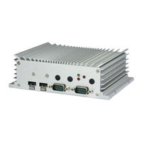
VIA Technologies AMOS-3005 User Manual (76 pages)
Ultra-compact fanless system
Brand:
VIA Technologies
| Category:
Industrial PC
| Size: 8.62 MB
Table of Contents
Table of Contents
5
1 Product Overview
11
Key Features
11
High-Performance
11
Fanless and Ruggedized Chassis
11
Optimized Integration with Multiple I/O Access
11
Networking Support
11
Storage Expansion
11
Support for a Wide Range of Power Sources
11
Wide Range of Operating Temperatures
11
Shock and Vibration Resistant
11
Embedded Operating System Ready
12
Product Specifications
13
Layout Diagram
16
Figure 1: Front Panel I/O Layout
16
Figure 2: Back Panel I/O Layout
16
Product Dimensions
17
Figure 3: Dimensions of the VIA AMOS-3005 (Front View)
17
Figure 4: Dimensions of the VIA AMOS-3005 (Top View)
17
2 External I/O Pin Descriptions and Functionality
18
Power On/Off Button
18
LED Indicators
18
Figure 5: Power On/Off Button Diagram
18
Figure 6: Leds Indicator Diagram
18
COM Ports
19
Lockable USB 2.0 Ports
19
Figure 7: COM Port Diagram
19
Figure 8: Lockable USB 2.0 Port Diagram
19
Table 1: COM Port Pinouts
19
Table 2: Lockable USB 2.0 Ports Pinouts
19
Gigabit Ethernet Ports
20
Figure 9: Gigabit Ethernet Port Diagram
20
Table 3: Gigabit Ethernet Port Pinouts
20
Table 4: Gigabit Ethernet Port LED Color Definition
20
VGA Port
21
USB 3.0 Ports
21
Figure 10: VGA Port Diagram
21
Figure 11: USB 3.0 Port Diagram
21
Table 5: VGA Port Pinouts
21
Table 6: USB 3.0 Ports Pinouts
21
HDMI ® Port
22
Audio Jacks
22
Figure 12: HDMI ® Port Diagram
22
Figure 13: Audio Jacks Diagram
22
Table 7: HDMI ® Port Pinouts
22
Table 8: Audio Jacks Receptacle Description
22
DC-In Jack
23
DIO Port
23
Figure 14: DC-In Jack Diagram
23
Figure 15: DIO Port Diagram
23
Table 9: DC-In Jack Pinouts
23
Table 10: DIO Port Pinouts
23
3 Onboard I/O
24
USB 2.0 Pin Header
24
Figure 16: USB 2.0 Pin Header Diagram
24
Table 11: USB 2.0 Pin Header Pinouts
24
USB Wi-Fi Connector
25
Figure 17: USB Wi-Fi Connector Diagram
25
Table 12: USB Wi-Fi Connector Pinouts
25
Minipcie Slot
26
SIM Card Slot
26
Figure 18: Minipcie Slot Diagram
26
Figure 19: SIM Card Slot Diagram
26
Msata Slot
27
Figure 20: Msata Slot Diagram
27
DDR3 SODIMM Slot
28
Figure 21: DDR3 SODIMM Slot Diagram
28
4 Onboard Jumper
29
Figure 22: Jumper Settings Example
29
COM Voltage Jumpers
30
Figure 23: JCOMV1 Voltage Jumper Diagram
30
JCOMV1 Voltage Jumper
30
Table 13: JCOMV1 Voltage Jumper Settings
30
Figure 24: JCOMV2 Voltage Jumper Diagram
31
JCOMV2 Voltage Jumper
31
Table 14: JCOMV2 Voltage Jumper Settings
31
USB 2.0 Power Type Jumper
32
Figure 25: USB 2.0 Power Type Jumper Diagram
32
Table 15: USB 2.0 Power Type Jumper Settings
32
5 Hardware Installation
33
Installing the DDR3 SODIMM Memory
33
Figure 26: Unscrewing the Front and Back Panel Plates
33
Figure 27: Removing the Front and Back Panel Plates
33
Figure 28: Removing the Bottom Cover Plate
34
Figure 29: Unscrewing the VIA EMIO-2004 Daughterboard
34
Figure 30: Removing the VIA EMIO-2004 Daughterboard
35
Figure 31: Peeling off the Memory Thermal Pad Protective Cover
35
Figure 32: Installing the DDR3 SODIMM Memory Module
36
Removing the DDR3 SODIMM Memory
37
Figure 33: Disengaging the DDR3 SODIMM Locking Clips
37
Figure 34: Removing the DDR3 SODIMM Memory Module
37
Installing the Msata Flash Drive Module
38
Figure 35: Installing the Msata Thermal Pad
38
Figure 36: Peeling off the Protective Plastic Cover of Msata Thermal Pad
38
Figure 37: Inserting the Msata Module
39
Figure 38: Securing the Msata Module
39
Figure 39: Applying Thermal Grease on Msata Heatsink
40
Reinstalling the VIA EMIO-2004 Daughterboard
41
Figure 40: Reinstalling VIA EMIO-2004 Daughterboard
41
Figure 41: Securing VIA EMIO-2004 Daughterboard
41
Inserting the SIM Card
42
Figure 42: Inserting the SIM Card
42
Installing the Rubber Feet
43
Figure 43: Installing the Rubber Feet
43
Installing the VIA AMOS-3005
44
Mounting the VIA AMOS-3005 on Wall/Table
44
Figure 44: Mounting the VIA AMOS-3005
44
Mounting the VIA AMOS-3005 Behind the Monitor
45
Figure 45: Installing the VESA Mounting Plate
45
Figure 46: Installing VIA AMOS-3005 to the VESA Mounting Plate
46
6 BIOS Setup
47
Entering the BIOS Setup Utility
47
Control Keys
47
Getting Help
47
System Overview
48
BIOS Information
48
Memory Information
48
System Language
48
System Date
48
System Time
48
Figure 47: Illustration of the Main Menu Screen
48
Advanced Settings
49
Figure 48: Illustration of the Advanced Settings Screen
49
ACPI Settings
50
ACPI Sleep State
50
Enable Hibernation
50
Figure 49: Illustration of the ACPI Settings Screen
50
S5 RTC Wake Settings
51
Figure 50: Illustration of the S5 RTC Wake Settings Screen
51
Wake System with Dynamic Time
51
Wake System with Fixed Time
51
CPU Configuration
52
Figure 51: Illustration of the CPU Configuration Screen
52
SATA Configuration
53
Figure 52: Illustration of the SATA Configuration Screen
53
SATA Mode
53
USB Configuration
54
EHCI Hand-Off
54
Figure 53: Illustration of the USB Configuration Screen
54
Legacy USB Support
54
USB Mass Storage Driver Support
54
USB3.0 Support
54
XHCI Hand-Off
54
F71869 Super IO Configuration
55
Figure 54: Illustration of the F71869 Super IO Configuration Screen
55
Serial Port
55
Serial Port 1 Configuration
55
Serial Port 2 Configuration
55
Uart Transmission Mode
55
F71869 H/W Monitor
56
Figure 55: Illustration of the F71869 H/W Monitor
56
Clock Generator Configuration
57
CPU Spread Spectrum
57
Figure 56: Illustration of the Clock Generator Configuration Screen
57
Pcie Spread Spectrum
57
Chipset Settings
58
Figure 57: Illustration of the Chipset Settings Screen
58
DRAM Configuration
59
DRAM Clock
59
Figure 58: Illustration of the DRAM Configuration Screen
59
VGA Share Memory (Frame Buffer)
59
Video Configuration
60
Figure 59: Illustration of the Video Configuration Screen
60
Select Display Device 1 and 2
60
Select Display Device Control
60
PMU_ACPI Configuration
61
AC Loss Auto-Restart
61
Figure 60: Illustration of the PMU_ACPI Configuration Screen
61
USB S4 Wakeup
61
HDAC Configuration
62
Figure 61: Illustration of the HDAC Configuration Screen
62
Onchip HDAC Device
62
Others Configuration
63
Figure 62: Illustration of the Others Configuration Screen
63
WATCHDOG Timer ACTION
63
WATCHDOG Timer COUNT
63
WATCHDOG Timer Enable
63
WATCHDOG Timer RUN/STOP
63
Boot Settings
64
Boot Configuration
64
Bootupnumlock State
64
Display Logo
64
Setup Prompt Timeout
64
Boot Option Priorities
64
Figure 63: Illustration of the Boot Settings Screen
64
Launch PXE Oprom Policy
64
Security Settings
65
Administrator Password/User Password
65
Figure 64: Illustration of the Security Settings Screen
65
Save & Exit
66
Save Changes and Exit
66
Discard Changes and Exit
66
Save Changes and Reset
66
Discard Changes and Reset
66
Save Changes
66
Discard Changes
66
Figure 65: Illustration of the Save & Exit Screen
66
Save as User Defaults
67
Restore User Defaults
67
7 Software and Technical Support
68
Windows and Linux Support
68
Driver Installation
68
Technical Support and Assistance
68
Appendix A. Installing Wireless Accessories
69
Installing the VIA EMIO Minipcie Module
69
Figure 66: Inserting the VIA EMIO Minipcie Module
69
Figure 67: Securing the VIA EMIO Minipcie Module
69
Figure 68: Removing the 4G Antenna Hole Cover
70
Figure 69: Removing the GPS Antenna Hole Cover
70
Figure 70: Removing the Wi-Fi Antenna Hole Cover
70
Figure 71: Installing the 4G Antenna Cable and Antenna
71
Figure 72: Installing the GPS Antenna Cable and Antenna
71
Figure 73: Installing the Wi-Fi Antenna Cable and Antenna
72
Figure 74: Connecting the 4G/Gps/Wi-Fi Antenna Cable to VIA EMIO Minipcie Module
72
Installing the VIA EMIO USB Wi-Fi Module
73
Figure 75: Installing the VIA EMIO USB Wi-Fi Module
73
Figure 76: Connecting the USB Wi-Fi Cable
73
Figure 77: Removing the Wi-Fi Antenna Hole Cover
74
Figure 78: Installing the Wi-Fi Antenna
74
Figure 79: Connecting the Wi-Fi Antenna Cable to VIA EMIO USB Wi-Fi Module
75
Advertisement
VIA Technologies AMOS-3005 User Manual (91 pages)
Fanless and Ultra Compact Embedded System
Brand:
VIA Technologies
| Category:
Desktop
| Size: 4.78 MB
Table of Contents
Regulatory Compliance
3
Safety Precautions
4
Box Contents
5
Optional Accessories
5
Ordering Information
5
Table of Contents
6
1 Product Overview
12
Key Features
12
Powered by VIA Eden X4 Processor
12
Fanless and Ruggedized Chassis Design
12
Networking Support
13
Empowered Multimedia Capabilities
13
Optimize Integration with Multiple I/O Access
13
SIM Card Socket
13
Storage Expansion
13
Wide Range of Power Sources
13
Wide Range of Operating Temperatures
13
Shock Resistant
13
Multiple Mounting Solutions
14
Embedded os Ready
14
Product Specifications
15
Layout Diagram
19
Dimensions
20
2 External I/O Pin Descriptions and Functionality
21
Front Panel I/O
21
Power Button
21
LED Indicators
21
COM Connector
22
Lockable USB 2.0 Port
23
Rear Panel I/O
24
LAN Port (Gigabit Ethernet)
24
USB 3.0 Ports
25
HDMI Port
26
VGA Connector
27
Audio Jacks
28
DC-In Power Input Connector
28
Digital I/O Connector
29
3 Onboard Connector and Pin Header
30
USB 2.0 Pin Header
30
WLAN Connector
31
Mini Pcie Slot
32
SIM Card Socket
33
Msata Slot
33
DDR3 SODIMM Socket
34
Onboard Jumpers Onboard Jumpers
35
COM Voltage Select Jumpers
36
JCOMV1 Voltage Select Jumper
36
JCOMV2 Voltage Select Jumper
37
USB 2.0 Power Type Select Jumper
38
Hardware Installation
40
Installing the DDR3 SODIMM Memory
40
Removing the DDR3 SODIMM Memory
45
Installing the Msata Flash Drive Module
46
Reinstalling the EMIO-2004 Daughterboard
49
Inserting the SIM Card
50
Installing the 3G/Gps/Wi-Fi Mini Pcie Module
51
Installing the WLAN (Wi-Fi) USB Module
56
Installing the Rubber Feet
59
Installing the AMOS-3005
60
Mounting the AMOS-3005 on Wall/Table
60
Mounting the AMOS-3005 Behind the Monitor
61
BIOS Setup BIOS Setup
64
BIOS Setup
64
Entering the BIOS Setup Utility
64
Control Keys
64
Getting Help
64
System Overview
65
BIOS Information
65
Memory Information
65
System Language
66
System Date
66
System Time
66
Advanced Settings
67
ACPI Settings
68
S5 RTC Wake Settings
69
CPU Configuration
70
SATA Configuration
71
USB Configuration
72
F71869 Super IO Configuration
74
F71869 H/W Monitor
75
Clock Generator Configuration
76
Chipset Settings
77
DRAM Configuration
78
Video Configuration
80
PMU_ACPI Configuration
81
HDAC Configuration
82
Others Configuration
83
Boot Settings
85
Boot Configuration
85
Boot Option Priorities
86
Security Settings
87
Save & Exit
88
Save Changes and Exit
88
Discard Changes and Exit
88
Save Changes and Reset
88
Discard Changes and Reset
89
Save Changes
89
Discard Changes
89
Save as User Defaults
89
Restore User Defaults
89
Software and Technical Supports
90
Microsoft and Linux Support
90
Driver Installation
90
Technical Supports and Assistance
90
Advertisement
Related Products
VIA Technologies AMOS-3001
VIA Technologies AMOS-820-2Q10A2
VIA Technologies AMOS-820-5Q10A1
VIA Technologies AMOS-820-6Q10A1
VIA Technologies AMOS-820-1Q10A2
VIA Technologies ARTiGO-A1200
VIA Technologies ARTiGO-A1250
VIA Technologies ARTIGO A900
VIA Technologies ARTiGO A800
VIA Technologies ARTiGO A1250
VIA Technologies Categories
Motherboard
Computer Hardware
Desktop
Control Unit
Industrial PC
More VIA Technologies Manuals
Login
Sign In
OR
Sign in with Facebook
Sign in with Google
Upload manual
Upload from disk
Upload from URL