Sign In
Upload
Manuals
Brands
Vertiv Manuals
Computer Hardware
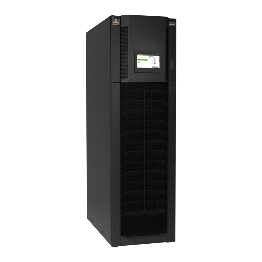
Liebert CRV
Vertiv Liebert CRV Manuals
Manuals and User Guides for Vertiv Liebert CRV. We have
3
Vertiv Liebert CRV manuals available for free PDF download: Installer/User Manual, Application Manual
Vertiv Liebert CRV Installer/User Manual (194 pages)
Row-based Cooling System
Brand:
Vertiv
| Category:
Computer Hardware
| Size: 39 MB
Table of Contents
Table of Contents
3
1 Important Safety Instructions
7
2 Nomenclature and Components
13
Model-Number Nomenclature
13
Component Location
13
Liebert CRV Description
14
Vertiv Smartrow M Icr O-Data Center Solution
15
3 Pre-Installation Preparation and Guidelines
17
Planning Dimensions
17
Unit Weights
17
4 Equipment Inspection and Handling
19
Packaging Material
20
Handling the Unit While Packaged
20
Moving 600-MM
20
Removing Packaging from 600-MM
21
Removing 600-MM
22
Reattaching Baffle Panel-600 MM
24
Removing Packaging from 300-MM
25
Removing 300-MM
26
5 Installing in Enclosure Row
27
Adjusting Base Supports/Leveling Feet
27
Optional Tie-Down Brackets for 300-MM
29
What's Included
29
Tools Required
30
Installing Tie-Down Brackets on 300-MM (12-In.) and on Cabinets of Different Heights
30
Installing Tie-Down Brackets on 300-MM (12-In.) and on Cabinets of the same Height
31
6 Piping and Refrigerant Requirements
33
Refrigerant Piping and Charging
34
Refrigerant Piping Guidelines for Air-Cooled Systems
35
Piping Guidelines for Liebert MC Condensers
36
Piping Layout and Condenser Positioning
37
Top or Bottom Connection for Refrigerant Piping on Air-Cooled Units
38
Heat-Rejection Line Sizes and Equivalent Lengths
39
Refrigerant Charge Requirements for Air-Cooled Systems
40
Evacuation, Leak-Testing, and Charging Air-Cooled Systems Without Receivers
43
Evacuation, Leak-Testing, and Charging Air-Cooled Systems with Liebert Lee-Temp "Flooded-Condenser" Head-Pressure Control System
47
Superheat and Refrigerant Charge Optimization
50
Fluid Piping for Air-Cooled, Water/Glycol-Cooled and Chilled-Water Piping Applications
51
Water/Glycol Loop Piping Guidelines
51
Chilled-Water Loop Piping
56
Humidifier Water-Supply Line Requirements
58
Leak Checking for Unit and Field-Installed Fluid Piping
59
Condensate-Pump Drain Line Requirements
60
Condensate-Pump Drain Piping for 300-MM (12-In.) Models
61
Field-Installed, Gravity-Fed Drain Line Requirements
67
7 Electrical Connections
73
Power-Supply Cable-Connection Guidelines
73
Wiring Connections
73
Electrical Field-Connection Descriptions
74
Locating the Serial Tag and Removing the Electrical Panel on 600-MM (24-In.) Units
74
Cable-Entry Points on 600-MM (24-In.) Units
76
Protective Features of Electrical Heaters-600-MM (24-In.) Units
77
Accessing the Electrical Panel on 300-MM (12-In.) Units
77
Releasing the Electric-Panel Lock
78
Protective Features of the Electronically-Commutated (EC) Fans-All Models
79
8 Humidifier-600-MM (24-In.) Units Only
81
Principal of Operation
81
Connecting Water Supply to the Humidifier
82
Humidifier Start-Up and Operation
82
Low Water Conductivity
83
Humidifier Canister Replacement
84
Removing the Old Canister
84
Mandatory Cleaning of the Drain Valve
85
Installing the New Canister
86
Humidifier Maintenance During Extended Shutdown
87
Humidifier Troubleshooting
87
Humidifier Troubleshooting Steps
89
9 Liebert Icom Hardware Installation
91
Installing Wired Remote Sensors
91
Setting DIP Switches and Labeling 2T Sensors
91
Terminating the Last Sensor on the Canbus Link
94
Routing Canbus Cable and Preparing for Sensor Installation
95
Installing 2T Sensors in the Racks to Monitor
100
Connecting the Canbus Cable and Ground
103
U2U Network Installation
105
Required Network Equipment
105
Plan Wiring Runs
105
U2U Wiring Connection
105
Wiring Cooling Units Without Wall-Mount Displays
106
Wiring Cooling Units with Wall-Mount Displays
108
10 Start-Up
111
Checks to Perform after Start-Up
112
Automatic Restart
112
Chilled Water Valve- All Chilled-Water Models
114
Adjust Baffles to Direct Air Properly
116
Adjusting Baffles-600-MM (24-In.)
116
Adjusting Blocker Plate-600-MM (12-In.)
117
Adjusting Baffles-300-MM (12-In.)
118
11 Monitoring and Managing the Liebert CRV with Liebert® Icom
121
Automatic Restart after Power Failure
121
Loss-Of-Power Notification
121
Variable-Speed Fan Control
121
Manual Fan-Speed Control
121
Automatic Fan-Speed Control
122
Minimum Fan Speed
123
Compressor Protection
123
Advanced DX Freeze Protection
123
Advanced DX High-Pressure Protection
123
High-Pressure Lock-Off
123
High-Temperature Lock-Off for Digital-Scroll Compressors
124
Short-Cycle Protection
125
Motorized Ball Valves for Water/Glycol-Cooled Units with Digital-Scroll Compressors
125
12 Troubleshooting
127
13 Maintenance
133
Safety Instructions
133
Facility Fluid and Piping Maintenance for Water and Glycol Systems
134
Glycol Solution Maintenance
134
Spare Parts
134
Maintenance Schedule
134
Thermostatic Expansion Valve (TXV) Maintenance
136
Determining Suction Superheat
136
Adjusting Superheat Setting with the TXV
136
Inspect and Replace the Air Filters-600-MM (24-In.) Models
137
Inspect and Replace the Air Filters-300-MM (12-In.) Models
139
Condensate-Drain and Condensate-Pump System Maintenance
140
Condensate Drain
140
Condensate Pump, Dual-Float
140
Air-Cooled Condenser and Drycooler Maintenance
141
Electric Reheat Maintenance
141
Fan Replacement
141
Replacing a Fan in 600-MM (24-In.) Models
141
Replacing a Fan in 300-MM (12-In.) Models
142
Considerations When Dismantling the Unit
144
F-Gas Regulation (EC) No. 842/2006
144
14 Preventive Maintenance Worksheet
147
Advertisement
Vertiv Liebert CRV Installer/User Manual (180 pages)
Row Based Cooling System
Brand:
Vertiv
| Category:
Accessories
| Size: 7 MB
Table of Contents
Table of Contents
3
1 Important Safety Instructions
7
2 Nomenclature and Components
13
Model Number Nomenclature
13
Component Location
13
Cooling Configurations and Liebert® CRV Overview
14
3 Pre-Installation Preparation and Guidelines
15
Planning Dimensions
15
Unit Weights
15
4 Equipment Inspection and Handling
17
Packaging Material
18
Handling the Unit While Packaged
18
Unpacking the Export Shipped 600 MM (24 In.) Unit
18
Unpacking the Domestic Shipped 600 MM (24 In.) Unit
19
Removing 600 MM (24 In.) Units from the Pallet
20
Unpacking the Export Shipped 300 MM (24 In.) Unit
22
Unpacking the Domestic Shipped 300 MM (12 In.) Unit
23
Removing 300 MM (12 In.) Units from the Pallet
24
5 Installing in Enclosure Row
27
Adjusting Base Supports/Leveling Feet
27
Optional Tie down Brackets for 300 MM (12 In.) Units
29
What's Included
29
Tools Required
30
Installing Tie down Brackets on 300 MM (12 In.) and on Cabinets of Different Heights
30
Installing Tie down Brackets on 300 MM (12 In.) and on Cabinets of the same Height
32
6 Piping and Refrigerant Requirements
33
Drain and Humidifier Fluid Piping
34
Humidifier Water Supply Line Requirements
34
Condensate Pump Drain Line Requirements
35
Condensate Pump Drain Piping for 300 MM (12 In.) Models
36
Field Installed, Gravity Fed Drain Line Requirements
42
Refrigerant Piping and Charging
47
Refrigerant Piping Guidelines for Air Cooled Systems
48
Piping Guidelines for Liebert® MC Condensers
49
Piping Layout and Condenser Positioning
50
Top or Bottom Connection for Refrigerant Piping on Air Cooled Units
51
Refrigerant Line Sizes and Equivalent Lengths
52
Refrigerant Charge Requirements for Air Cooled Systems
53
Additional Oil Requirements for Digital Scroll Compressors
56
Evacuation, Leak Testing, and Charging Air Cooled Systems Without Receivers
58
Evacuation, Leak Testing, and Charging Air Cooled Systems with Liebert® Lee-Temp Flooded Condenser Head Pressure Control System
62
Superheat and Refrigerant Charge Optimization
64
Water/Glycol Loop Piping Guidelines
65
Glycol Mixture
68
Water/Glycol Cooled Piping Connections
68
Leak Checking for Unit and Field Installed Piping
70
Chilled Water Loop Piping
70
7 Electrical Connections
73
Power Supply Cable Connection Guidelines
73
Wiring Connection Guidelines
73
Electrical Field Connections Descriptions
74
Locating the Serial Tags and Removing the Electrical Panel on 600 MM (24 In.) Units
74
Cable Entry Points on 600 MM (24 In.) Units
77
Protective Features of Electrical Heaters-600-MM (24-In.) Units
78
Accessing the Electrical Panel on 300 MM (12 In) Units
78
Releasing the Electric Panel Lock
79
Protective Features of the Electronically Commutated (EC) Fans-All Models
80
8 Humidifier 600 MM (24 In.) Units Only
83
Principal of Operation
83
Connecting Water Supply to the Humidifier
84
Humidifier Startup and Operation
85
Low Water Conductivity
85
Humidifier Canister Replacement
85
Removing the Old Canister
86
Mandatory Cleaning of the Drain Valve
87
Installing the New Canister
88
Humidifier Maintenance During Extended Shutdown
89
Humidifier Troubleshooting
89
Humidifier Troubleshooting Steps
91
9 Startup
93
Checks to Perform after Startup
94
Automatic Restart
95
Chilled Water Valve- All Chilled Water Models
96
Adjust Baffles to Direct Air Properly
97
Adjusting Baffles-600 MM (24 In.)
98
Adjusting Blocker Plate-600 MM (12 In.)
99
Adjusting Baffles-300 MM (12 In.)
100
10 Troubleshooting
103
11 Maintenance
107
Safety Instructions
107
Facility Fluid and Piping Maintenance for Water and Glycol Systems
108
Glycol Solution Maintenance
108
Spare Parts
108
Maintenance Schedule
108
Thermostatic Expansion Valve (TXV) Maintenance
110
Determining Suction Superheat
110
Adjusting Superheat Setting with the TXV
111
Compressor Maintenance
111
Compressor Oil
111
Replacement Compressors
111
Rotalock Valve on Digital Scroll Compressors
112
Unloading Solenoid(S) on a Digital Scroll Compressor
112
Compressor Electrical Failure (Motor Burnout)
113
Compressor Mechanical Failure
113
Replacing a Compressor with Mechanical Failure
113
Inspect and Replace the Air Filters-600 MM (24 In.) Models
114
Inspect and Replace the Air Filters-300 MM (12 In.) Models
116
Condensate Drain and Condensate Pump System Maintenance
117
Condensate Drain
117
Condensate Pump, Dual Float
117
Air-Cooled Condenser and Drycooler Maintenance
118
Electric Reheat Maintenance
118
Fan Replacement
119
Replacing a Fan in 600 MM (24 In.) Models
119
Replacing a Fan in 300 MM (12 In.) Models
120
Considerations When Dismantling the Unit
121
F-Gas Regulation (EC) No. 842/2006
122
12 Preventive Maintenance Worksheet
125
Appendices
131
Appendix A: Technical Support and Contacts
131
Appendix B: Model Number Nomenclature Detail
133
Appendix C: Submittal Drawings
137
Vertiv Liebert CRV Application Manual (18 pages)
Air-Cooled, Water/Glycol-Cooled and Chilled Water, 50 & 60Hz
Brand:
Vertiv
| Category:
Accessories
| Size: 1 MB
Table of Contents
Table of Contents
3
1 What Is the Liebert CRV
5
Liebert CRV Intended Application
5
2 Liebert CRV Controls
7
Liebert CRV Sensor Location Guidelines
8
3 General Liebert CRV Guidelines
9
4 Site Application and Unit Placement
11
Advertisement
Advertisement
Related Products
Vertiv Liebert PDX
Vertiv Liebert CRV Plus
Vertiv Liebert CRV+ CW Series
Vertiv Liebert CW
Vertiv Liebert CW Series
Vertiv Liebert CROSS RACK
Vertiv Liebert XDCF
Vertiv Liebert LVC
Vertiv Liebert EFC
Vertiv Liebert PCW
Vertiv Categories
UPS
Power Supply
Switch
Power distribution unit
Air Conditioner
More Vertiv Manuals
Login
Sign In
OR
Sign in with Facebook
Sign in with Google
Upload manual
Upload from disk
Upload from URL