Vertiv Liebert CRV Installer/User Manual
Row-based cooling system
Hide thumbs
Also See for Liebert CRV:
- Application manual (18 pages) ,
- Installer/user manual (180 pages)

Related Manuals for Vertiv Liebert CRV


Summary of Contents for Vertiv Liebert CRV
- Page 1 Liebert® CRV™ Row-based Cooling System 600-mm and 300-mm Wide Installer/User Guide...
- Page 2 Technical Support Site If you encounter any installation or operational issues with your product, check the pertinent section of this manual to see if the issue can be resolved by following outlined procedures. For additional assistance, visit https://www.VertivCo.com/en-us/support/...
-
Page 3: Table Of Contents
6.2.6 Evacuation, Leak-testing, and Charging Air-cooled Systems with Liebert Lee-Temp “Flooded-condenser” Head-pressure Control System 6.2.7 Superheat and Refrigerant Charge Optimization 6.3 Fluid Piping for Air-cooled, Water/Glycol-cooled and Chilled-water Piping Applications 6.3.1 Water/Glycol Loop Piping Guidelines 6.3.2 Chilled-water Loop Piping 6.3.3 Humidifier Water-supply Line requirements Vertiv | Liebert CRV Installer/User Guide |... - Page 4 9.2.2 Plan wiring runs 9.2.3 U2U Wiring connection 9.2.4 Wiring Cooling Units without Wall-mount Displays 9.2.5 Wiring Cooling Units with Wall-mount Displays 10 Start-up 10.1 Checks to Perform after Start-up 10.2 Automatic Restart Vertiv | Liebert CRV Installer/User Guide |...
- Page 5 13.11 Fan Replacement 13.11.1 Replacing a Fan in 600-mm (24-in.) Models 13.11.2 Replacing a Fan in 300-mm (12-in.) Models 13.12 Considerations when Dismantling the Unit 13.13 F-Gas Regulation (EC) No. 842/2006 14 Preventive Maintenance Worksheet Vertiv | Liebert CRV Installer/User Guide |...
- Page 6 Appendices Appendix A: Model-number Nomenclature Detail Appendix B: Submittal Drawings Vertiv | Liebert CRV Installer/User Guide |...
-
Page 7: Important Safety Instructions
SAVE THESE INSTRUCTIONS This manual contains important safety instructions that should be followed during the installation and maintenance of the Liebert CRV. Read this manual thoroughly before attempting to install or operate this unit. Only qualified personnel should move, install or service this equipment. - Page 8 POE oils also have a property that makes them act as a solvent in a refrigeration system. Maintaining system cleanliness is extremely important because the oil will tend to bring any foreign matter back to the compressor. Vertiv | Liebert CRV Installer/User Guide |...
- Page 9 Do not locate unit directly above any equipment that could sustain water damage. We recommend installing a monitored fluid-detection system to immediately discover and report coolant-fluid system and condensate drain-line leaks. Vertiv | Liebert CRV Installer/User Guide |...
- Page 10 Idle fluid allows the collection of sediment that prevents the formation of a protective oxide layer on the inside of tubes. Keep unit switched On and water/coolant fluid-supply circuit system operating continuously. Vertiv | Liebert CRV Installer/User Guide |...
- Page 11 Risk of release of hazardous substances into the environment. Can cause environmental pollution and violation of environmental regulations. The Liebert CRV contains substances and components hazardous for the environment (electronic components, refrigerating gases and oils). At the end of its useful life, the Liebert CRV must be dismantled by specialized refrigerating technicians.
- Page 12 Standard 60-Hz units are CSA certified to the harmonized U.S. and Canadian product safety standard CSA C22.2 No 236/UL 1995 for Heating and Cooling Equipment and are marked with the CSA c-us logo. Vertiv | Liebert CRV Installer/User Guide |...
-
Page 13: Nomenclature And Components
2 NOMENCLATURE AND COMPONENTS This section describes the model-number configuration for Liebert CRV units and components. 2.1 Model-number Nomenclature The tables describe the 25-digit configuration number. The 14-digit model number consists of the first 10 digits and last 4 digits of the configuration number. -
Page 14: Liebert Crv Description
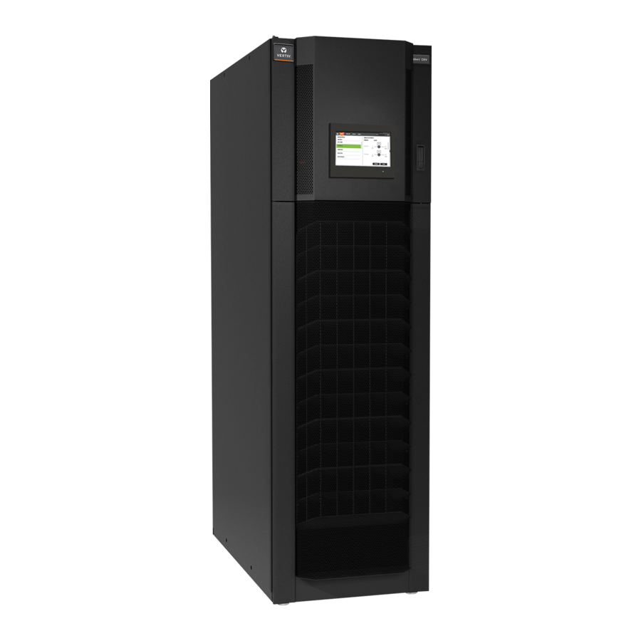
2.3 Liebert CRV Description The Liebert CRV is a precision cooling unit available in compressorized (air-, water- or glycol-cooled) and chilled-water configurations to be installed within a row of high-density computing racks in a “hot aisle- cold aisle” configuration. Air enters the rear of the CRV from the hot aisle, is filtered, cooled and conditioned, then discharged into the cold aisle. -
Page 15: Vertiv Smartrow M Icr O-Data Center Solution
2.4 Vertiv SmartRow Mic o-Data Center Solution The Vertiv™ SmartRow DCX is a comprehensive, micro-data center in a row. Starting with the IT requirements, all of the associated remote management, monitoring and infrastructure are configured to address the initial and future needs of the rack-mount equipment. This approach simplifies the entire process, from selection through to deployment, reducing the time, complexity and costs associated with alternative approaches. - Page 16 This page intentionally left blank. Vertiv | Liebert CRV Installer/User Guide |...
-
Page 17: Pre-Installation Preparation And Guidelines
For proper humidity control, keep outside or fresh air to an absolute minimum (less than 5% of total air circulated in the room). • Do not install a Liebert CRV in an alcove or at the end of a long, narrow room. • Install the units as close as possible to the largest heat load. - Page 18 683 (309.8) CR020 846 (384) 879 (399) — 953 (432) 986 (447) — CR035 912 (414) 956 (434) — 1019 (462) 1063 (482) — CR040 — — 835 (379) — — 942 (427) Vertiv | Liebert CRV Installer/User Guide |...
-
Page 19: Equipment Inspection And Handling
• Carefully inspect all items for visible or concealed damage. • Report damage immediately to the carrier and file a damage claim with a copy sent to Vertiv™ or to your sales representative. • For initial access use a 7/32-in. Allen wrench for panel removal. -
Page 20: Packaging Material
5. Move the unit to its installation location. Two or more properly trained and qualified personnel are required to move the unit to its installation location. 6. Lower the unit and remove the slings. Vertiv | Liebert CRV Installer/User Guide |... -
Page 21: Removing Packaging From 600-Mm
NOTE: The bag may remain in place to protect from dust and to protect the unit panels, or it may be removed for immediate installation. 4. Remove the bag from the unit when ready to remove the skid and install the unit. Vertiv | Liebert CRV Installer/User Guide |... -
Page 22: Removing 600-Mm
Open the top-panel door (with iCOM display) as shown Figure 4.4 on the facing page. • Using a T30 Torx screwdriver, remove the bottom baffle panel assembly, and set aside until needed for reattachment. • Close and latch the top panel door. Vertiv | Liebert CRV Installer/User Guide |... - Page 23 6. Using a 17-mm socket wrench, see Figure 4.5 on the next page, open-end wrench, or pliers, remove the 8 bolts (4 on each side) that secure the lift block to the skid, and remove the lift blocks from the skid. Vertiv | Liebert CRV Installer/User Guide |...
-
Page 24: Reattaching Baffle Panel-600 Mm
Open top panel door (with iCOM display), see Figure 4.4 on the previous page. 2. Reattach the bottom baffle panel assembly with screws, using a T30 Torx drive. 3. Close and latch top panel door. Vertiv | Liebert CRV Installer/User Guide |... -
Page 25: Removing Packaging From 300-Mm
2. Remove all exterior packaging from around the unit. 3. Remove the bag from the unit when ready to remove the skid and install the unit. Figure 4.6 Removing packaging from unit ITEM DESCRIPTION Retaining clip Packaging removal Vertiv | Liebert CRV Installer/User Guide |... -
Page 26: Removing 300-Mm
3. Roll the unit down the ramp and off the pallet onto a flat surface. IMPORTANT! Two or more properly trained and qualified personnel are required to move the unit to its installation location. Figure 4.7 Installing ramps and removing shipping brackets ITEM DESCRIPTION Ramp Shipping bracket Vertiv | Liebert CRV Installer/User Guide |... -
Page 27: Installing In Enclosure Row
5 INSTALLING IN ENCLOSURE ROW Built-in casters let you roll the Liebert CRV into position for installation. Stabilizers reduce the likelihood of the module tipping over. These stabilizers, shown in Figure 5.1 on the next page, must be removed before the unit is positioned in the row. - Page 28 ITEM DESCRIPTION Rear of 300-mm (12-in.) unit, bottom view Rear of 600-mm (24-in.) unit, bottom view Caster, 1 at each corner Stabilizer, 1 at each corner Adjustable leveling foot, 1 at each corner Vertiv | Liebert CRV Installer/User Guide |...
-
Page 29: Optional Tie-Down Brackets For 300-Mm
Brackets: 4 (2-piece, L-shaped components; for cabinets of different heights) • Bracket tie-downs: 2 (flat brackets; for cabinets of same height) • M6 bolts: 2 • M6 nuts: 2 • Washers: 2 • Self-tapping screws: 16 Vertiv | Liebert CRV Installer/User Guide |... -
Page 30: Tools Required
2. Secure the tie-down bracket loosely with the washer and M6 nut. 3. Position the tie-down bracket over the factory-fabricated holes on the top of the Liebert CRV and over the top of the adjacent cabinet as shown in Figure 5.3 on the facing page. -
Page 31: Installing Tie-Down Brackets On 300-Mm (12-In.) And On Cabinets Of The Same Height
To install the tie-down bracket: Position the tie-down bracket over the factory-fabricated holes on the top of the Liebert CRV and over the top of the adjacent cabinet of the same height as shown in Figure 5.4 on the next page. - Page 32 5. Position the bracket over the holes in the Liebert CRV and the adjacent cabinet. 6. Insert and tighten the four screws. Figure 5.4 Tie-down bracket on cabinets of the same height—300 mm (12 in.) ITEM DESCRIPTION Top of adjacent cabinet...
-
Page 33: Piping And Refrigerant Requirements
DPN003040 Connection Locations, 300mm (12in.) Water/Glycol Cooled Models Chilled-water Systems DPN001794 Connection Locations, CR040R Chilled Water Models DPN002814 Connection Locations 300mm (12in.) Air Cooled Models DPN002815 Connection Locations, 300mm (12in.) Chilled Water Models Vertiv | Liebert CRV Installer/User Guide |... -
Page 34: Refrigerant Piping And Charging
POE oils also have a property that makes them act as a solvent in a refrigeration system. Maintaining system cleanliness is extremely important because the oil will tend to bring any foreign matter back to the compressor. Vertiv | Liebert CRV Installer/User Guide |... -
Page 35: Refrigerant Piping Guidelines For Air-Cooled Systems
Liebert CRV. • Consult Vertiv™ technical support if piping run exceeds 300 feet (91 m) equivalent length. • Keep piping clean and dry, especially on units with R-410A refrigerant. •... -
Page 36: Piping Guidelines For Liebert Mc Condensers
(for example, on the receiver, on the low- pressure side, and on the compressor delivery). 6. Cut the spun-closed ends off the hot-gas and liquid-line connections on the Liebert CRV. Vertiv | Liebert CRV Installer/User Guide |... -
Page 37: Piping Layout And Condenser Positioning
5. There must be at least 1 in. (25 mm) separation between the gas and liquid pipelines. If this is not possible, insulate both lines. 6. Support both horizontal and vertical pipes with vibration-damping clamps, which include rubber gaskets. Place these clamps every 5 to 7 ft (1.5 to 2 m). Vertiv | Liebert CRV Installer/User Guide |... -
Page 38: Top Or Bottom Connection For Refrigerant Piping On Air-Cooled Units
6.2.2 Top or Bottom Connection for Refrigerant Piping on Air-cooled Units The Liebert CRV can be connected to a condenser through either the top or bottom of the unit. The unit is piped for connections at the top of the unit, shown in Figure 6.1 below, with provisions for connection through the bottom. -
Page 39: Heat-Rejection Line Sizes And Equivalent Lengths
1-1/8 (28.6)* 7/8 (22.2) Contact your Vertiv™ representative for line sizing for runs longer than 300 ft. (91.4 m) equivalent length. *Must down-size vertical riser one trade size (1-1/8” to 7/8”, 7/8” to 3/4”, 3/4” to 5/8”, 5/8” to 1/2”). Source: DPN000788, Rev. 5... -
Page 40: Refrigerant Charge Requirements For Air-Cooled Systems
Source: DPN002167, Rev. 7 6.2.4 Refrigerant Charge Requirements for Air-cooled Systems The following tables provide the refrigerant charge requirements for the Liebert CRV, connected piping and condenser options. Table 6.8 R410-A refrigerant charge and oil charge for air-cooled Liebert CRV... - Page 41 CONDENSERS WITHOUT LIEBERT LEE-TEMP CONDENSERS WITH LIEBERT LEE-TEMP MCS028 2.5 (1.2) 21.7 (9.8) MCM040 3.5 (1.6) 22.7 (10.3) MCM080 8.5 (3.8) 39.8 (18.1) MCL055 5.0 (2.3) 24.2 (11.0) MCL110 10.7 (4.9) 49.1 (22.3) Vertiv | Liebert CRV Installer/User Guide |...
- Page 42 Figure 6.3 Connections for vacuum creation and refrigerant charge—Air-cooled, 600 mm (24 in.) ITEM DESCRIPTION Suction, liquid, and discharge service connections Liquid-line service connection (close-up view of the center callout in Item 1) High-pressure switch Pressure transducer Vertiv | Liebert CRV Installer/User Guide |...
-
Page 43: Evacuation, Leak-Testing, And Charging Air-Cooled Systems Without Receivers
2. Connect refrigerant gauges to the suction rotalock valves and discharge-line Schrader valves. 3. Open the service valves and place a 150 PSIG (1034 kPa) of dry nitrogen with a tracer of refrigerant. Check system for leaks with a suitable leak detector. Vertiv | Liebert CRV Installer/User Guide |... - Page 44 Charge by subcooling measurement at the indoor unit. See Table 6.11 on page 46 for target subcooling temperatures. • Pressure and temperature measuring instruments should be capable of measuring to ±10 psig (68.9 kPa) and ± 2°F (1.1°C) for best subcooling measurement. Vertiv | Liebert CRV Installer/User Guide |...
- Page 45 0.5 lb (.23 kg). 5. Turn on the Liebert MC disconnect switch. 6. Turn on the Liebert CRV disconnect switch, and operate the unit for 30 minutes using the charging function for each circuit of the system.
- Page 46 70 (21.1) 17 (9.3) 80 (26.7) 13 (7.2) 90 (32.2) 9 (5.0) 95 (35.0) 7 (3.9) 100 (37.8) 5 (2.9) 105 (40.6) 3 (1.8) 110 (43.3) 1 (0.7) 125 (51.7) DPN002411, Rev. 8 Vertiv | Liebert CRV Installer/User Guide |...
-
Page 47: Evacuation, Leak-Testing, And Charging Air-Cooled Systems With Liebert Lee-Temp "Flooded-Condenser" Head-Pressure Control System
Liebert Lee-Temp system can be used with any compressor or expansion-valve choice. A discharge line and liquid line must be field-installed between the indoor unit and the outdoor condenser. See the appropriate piping schematic, listed in Table 6.1 on page 33. Vertiv | Liebert CRV Installer/User Guide |... - Page 48 Pull a second and third vacuum to 500 microns or less. Re-check the pressure after 2 hours. When the 3 checks are complete, remove the jumper hose from the service valve fitting and the condenser, and proceed to Charging Air-cooled Systems with Liebert Lee-Temp Receiver on the facing page. Vertiv | Liebert CRV Installer/User Guide |...
- Page 49 Sight Glass Levels at Outdoor Temperatures • 40°F (4.5°C) and lower—bottom sight glass is 3/4 full • 40 to 60°F (4.5 to 15.5°C)—bottom sight glass is full • 60°F (15.5°C) and higher—top sight glass is 3/4 full Vertiv | Liebert CRV Installer/User Guide |...
-
Page 50: Superheat And Refrigerant Charge Optimization
Optimizing Refrigerant Charge on Water/Glycol Units Liebert CRV water/glycol systems are factory-charged with R-410A refrigerant and will operate without refrigerant-charge adjustment at a wide range of return-air temperatures and water/glycol entering temperatures. Adjusting the factory refrigerant charge while operating the unit at full-load room conditions and at typical water/glycol temperatures can maximize the cooling capacity and unit efficiency. -
Page 51: Fluid Piping For Air-Cooled, Water/Glycol-Cooled And Chilled-Water Piping Applications
Risk of water leakage. Can cause severe property damage and loss of critical data center equipment. The Liebert CRV requires a water drain connection. The 600-mm (24-in.) model may require an external water supply to operate the humidifier. Improper installation, application and service practices can result in water leakage from the unit. - Page 52 Do not leave the water/coolant fluid-supply circuit in a no-flow condition. Idle fluid allows the collection of sediment that prevents the formation of a protective oxide layer on the inside of tubes. Keep unit switched On and water/coolant fluid-supply circuit system operating continuously. Vertiv | Liebert CRV Installer/User Guide |...
- Page 53 Place shut-off ball valves at the indoor unit inlet and outlet to allow easy maintenance. • Install a water drain system at the lowest point in the circuit. • Fully-drain the piping before connecting it to the cooling unit. Vertiv | Liebert CRV Installer/User Guide |...
- Page 54 Insulate both pipes. IMPORTANT! Add water and ethylene glycol to the circuit when the ambient temperature is below 32°F (0°C). Refer to the Liebert CRV System Design Manual, SL-11978). Do not exceed the nominal operating pressure of the circuit components.
- Page 55 Fill water Filling meter Stand-by pump (optional) Gauge Pressure-operated bypass Pump Thermal-management unit Safety valve Air separator Shut-off valve Charge group Thermostat (filter, reducer, check valve) Check valve Variex Drain (at lowest point) Vertiv | Liebert CRV Installer/User Guide |...
-
Page 56: Chilled-Water Loop Piping
Locate air vents at tops of all risers and any intermediate system high points. Figure 6.6 Bottom connections on chilled water units ITEM DESCRIPTION 600 mm (24 in.) unit 300 mm (12 in.) unit Chilled-water connections Vertiv | Liebert CRV Installer/User Guide |... - Page 57 Figure 6.7 Chilled-water circuit ITEM DESCRIPTION ITEM DESCRIPTION Insulation Ball valve Thermostat Water drain trap Pressure gauge Tubing support Liebert CRV Figure 6.8 Venting air trapped in a chilled-water unit ITEM DESCRIPTION Schrader valve on core Vertiv | Liebert CRV Installer/User Guide |...
-
Page 58: Humidifier Water-Supply Line Requirements
With dirty or muddy water sources (for example, some well sources), ensure proper filtration by adding an external filter to the water line entering the unit. (Consult your Vertiv™ for accessories such as filters.) NOTICE Risk of improper water supply. -
Page 59: Leak Checking For Unit And Field-Installed Fluid Piping
6.3.4 Leak Checking for Unit and Field-installed Fluid Piping The fluid systems in the Liebert CRV are factory-checked for leaks and may be shipped with a nitrogen holding charge. At installation, check all fluid circuits for leaks. NOTE: We recommend isolating the unit with field-installed shutoff valves during leak checking of field-installed piping. -
Page 60: Condensate-Pump Drain Line Requirements
Units with a condensate pump and humidifier are preset to be connected from the top. If floor connections are used, the water lines can be intercepted at the following points shown in Figure 6.9 on the facing page. Vertiv | Liebert CRV Installer/User Guide |... -
Page 61: Condensate-Pump Drain Piping For 300-Mm (12-In.) Models
• Connecting Discharge Hose on Air-cooled, 300-mm (12-in.) Models on the next page • Connecting Discharge Hose on Water/Glycol-cooled, 300-mm (12-in.) Models on page 63 • Connecting Discharge Hose on Chilled-water, 300-mm (12-in.) models on page 65 Vertiv | Liebert CRV Installer/User Guide |... - Page 62 1/2-in. MPT X 3/8-in. Hose-barb threaded adapter (factory-supplied) For top discharge: Connect the discharge tubing to the tubing exiting the top of the unit. For bottom discharge: Run the tubing out the bottom of the unit. Vertiv | Liebert CRV Installer/User Guide |...
- Page 63 Refer to the following figure and: Unbolt the fasteners that hold the condensate pump in the unit. 2. Unplug the fan wiring pin connectors from the fan control board and remove the fan control board. Vertiv | Liebert CRV Installer/User Guide |...
- Page 64 Figure 6.12 Condensate-pump drain piping, Water/Glycol-cooled, 300-mm (12-in.) ITEM DESCRIPTION Back panel Fan control board Bushing for bottom condensate exit (field-installed in drain-line knockout hole) Drain hose Wiring from electrical panel Wire tires on wiring routed inside frame Vertiv | Liebert CRV Installer/User Guide |...
- Page 65 4. Remove the knockout in the plate inside the bottom of the unit, and insert the bushing into the knockout. 5. Run the condensate-pump discharge hose through the bushing in the bottom of the unit. Vertiv | Liebert CRV Installer/User Guide |...
- Page 66 Condensate-drain tubing, top exit Bushing for bottom condensate exit (field-installed in drain-line knockout hole) Condensate pump Service loop of high- and low-voltage wiring for condensate-pump removal. Make sure the service loop remains, and coil as necessary. Vertiv | Liebert CRV Installer/User Guide |...
-
Page 67: Field-Installed, Gravity-Fed Drain Line Requirements
Refer to the additional details and specific installation instructions depending on the configuration of your unit: • Connecting Gravity-drain Line on All 600-mm (24-in.) models and on Air- and Water/Glycol-cooled, 300 mm (12 in.) models on the next page • Connecting Gravity-drain Line on Water/Glycol-cooled, 300-mm (12-in.) Models on page 70 • Connecting Gravity-drain Line on Chilled-water, 300-mm (12-in.) Models on page 71 Vertiv | Liebert CRV Installer/User Guide |... - Page 68 3. Run the evaporator drain line through the bushing in the bottom of the unit. 4. Connect field-installed drain line to the discharge hose. 5. Using field-supplied clamps, clamp all connections as needed. Vertiv | Liebert CRV Installer/User Guide |...
- Page 69 Bushing for installation after knockout is removed Adapter, 1-in. NPT Male – 3/4-in. barb When coolant supply/return is top-entry, remove this plate, remove the knockout for the drain, and then re-install the plate. Vertiv | Liebert CRV Installer/User Guide |...
- Page 70 Bushing (field-installed after knockout removed) Adapter, 1-in. NPT Male – 3/4-in. barb Access plate When coolant supply/return is top-entry, remove this plate, remove the knockout for the drain, and then re-install the plate. Vertiv | Liebert CRV Installer/User Guide |...
- Page 71 Knockout location below drain tubing (not visible in figure) Connect to field-supplied drain line 90-degree hose barb Condensate drain and trap under units without a condensate-drain pump Condensate drain tubing routed through bushing/knockout Vertiv | Liebert CRV Installer/User Guide |...
- Page 72 This page intentionally left blank. Vertiv | Liebert CRV Installer/User Guide |...
-
Page 73: Electrical Connections
Remote On/Off connections must be provided by the installer. • The General Alarm terminals allow remote alarm signaling. In case of short circuit, check the affected switch for sticking and replace it if necessary. Vertiv | Liebert CRV Installer/User Guide |... -
Page 74: Electrical Field-Connection Descriptions
This serial tag on the 600-mm (24-in.) unit is inside the display panel as shown in Figure 7.1 below. Figure 7.1 Serial tag location—600 mm (24 in.) ITEM DESCRIPTION Serial tag To access the electrical panels: Refer to Figure 7.2 on the facing page, and remove the bolts indicated. Vertiv | Liebert CRV Installer/User Guide |... - Page 75 Figure 7.2 Remove electrical panel and lower front panel—600 mm (24 in.) ITEM DESCRIPTION Bolts to remove for access to high-voltage electrical panel Bolts to remove for access to low-voltage electrical panel Bolts to remove to open lower front-baffle panel Vertiv | Liebert CRV Installer/User Guide |...
-
Page 76: Cable-Entry Points On 600-Mm (24-In.) Units
Low-voltage cables route from top entry, through the channel opening in the side panel, and connect bottom of the unit to the electrical panel. IntelliSlot bays Low-voltage bottom port entry Low-voltage cable path to electrical panel High-voltage bottom-entry knockout High-voltage cable path Vertiv | Liebert CRV Installer/User Guide |... -
Page 77: Protective Features Of Electrical Heaters-600-Mm (24-In.) Units
On until the panel is fully inside the unit. 3. Slide the electrical panel out of the unit until the slides on the panel locking. Releasing the Electric-panel Lock on the next page to slide the electrical panel into the unit. Vertiv | Liebert CRV Installer/User Guide |... -
Page 78: Releasing The Electric-Panel Lock
2. Then press the tab on the top slide while pushing the panel into the unit. 3. Lock the panel in place with the quarter-turn latch. NOTE: The main-disconnect switch will not switch to On until the panel is fully inside the unit. Vertiv | Liebert CRV Installer/User Guide |... -
Page 79: Protective Features Of The Electronically-Commutated (Ec) Fans-All Models
Overtemperature of motor • Locked rotor protection • Short circuit at the motor output When any of these failures occurs, the motor stops, electronically, with no potential for separation, and the status relay is released. Vertiv | Liebert CRV Installer/User Guide |... - Page 80 When all three phases return to correct values, the motor restarts automatically in 10 to 40 seconds. The power supply for an external speed-setting potentiometer is protected against short-circuiting. The motor is overload-protected via motor current limitation. Vertiv | Liebert CRV Installer/User Guide |...
-
Page 81: Humidifier-600-Mm (24-In.) Units Only
Water over-flow chamber Drain valve (safety drain in case of fill-valve/control-board failure) 1-in. air gap Drain canal (open to atmosphere) Fill cup Drain connection Condensate return (optional) Fill valve Steam hose Strainer Electrodes Tap-water supply Vertiv | Liebert CRV Installer/User Guide |... -
Page 82: Connecting Water Supply To The Humidifier
Check all electrical connections for wires that may have become loose in shipping. Components damaged because of loose connections are NOT under warranty. Vertiv | Liebert CRV Installer/User Guide |... -
Page 83: Low Water Conductivity
Open the plumbing compartment and add salt solution through cylinder outlet. Excessive amounts of salt will result in erratic operation of the unit; however, normalization of the unit will occur automatically through the solid-state control sequence. Vertiv | Liebert CRV Installer/User Guide |... -
Page 84: Humidifier Canister Replacement
The steam cylinder is disposable and must be replaced at the end of the cylinder's life. Cylinder life will vary according to water-supply conditions and humidifier use. Contact your local Vertiv™ representative to obtain a replacement cylinder. To obtain the correct cylinder, supply the cylinder model from the white 3-digit label on the cylinder, or supply the model, voltage and serial number from the unit specification label. -
Page 85: Mandatory Cleaning Of The Drain Valve
12. Fit mounting screws back through the drain-valve body, one through ring terminal on the green wire. Figure 8.3 Drain valve assembly ITEM DESCRIPTION ITEM DESCRIPTION Actuator Sleeve Plunger Holding coil Spring Male, slip-on connection tabs Vertiv | Liebert CRV Installer/User Guide |... -
Page 86: Installing The New Canister
Check steam generating humidifier electrode plugs to ensure that they are pressed firmly onto pins. Loose connections will cause overheating of cylinder and plugs. Figure 8.4 Sensor pins, cylinder plugs ITEM DESCRIPTION White sensor plug Sensor pin Cylinder plug Cylinder pin Vertiv | Liebert CRV Installer/User Guide |... -
Page 87: Humidifier Maintenance During Extended Shutdown
• Monitored leg is the primary wire to the cylinder that loops through the current sensing device of the main PCB. This wire ends at the red cylinder plug at the cylinder. Vertiv | Liebert CRV Installer/User Guide |... - Page 88 Check water level in the cylinder; should be about 3/4 full. 4 flashes in End of cylinder life - change cylinder. Check for foaming if water level is lower or cylinder life shorter than expected. sequence Change cylinder, clean drain valve. Vertiv | Liebert CRV Installer/User Guide |...
-
Page 89: Humidifier Troubleshooting Steps
Verify that drain valve operates freely when activated. Clean valve and replace if defective. rate Flush canister several times and replace if arcing persists. Excessive mineral Analyze mineral content of water. If mineral content is excessive contact Vertiv™ Technical content in water Support. 8.5.2 Humidifier Troubleshooting Steps Auto On/Off/Drain switch in On position—unit will not fill:... - Page 90 Review installation of steam line to ensure there are no blockages or excessive static pressure in the air system. Vertiv | Liebert CRV Installer/User Guide |...
-
Page 91: Liebert Icom Hardware Installation
Each Liebert CRV comes with 3 2T sensors standard. Although using and adding additional remote sensors is optional, we recommend attaching one remote sensor to each rack that the unit is intended to cool because they allow more efficient and effective operation of the cooling unit. - Page 92 CANbus run. If settings are incorrect, the control will not operate properly. The DIP switches in 2T sensors included with each Liebert CRV are factory-set according to Table 9.1 below. If adding additional 2T sensors, use the steps that follow to set the DIP switches.
- Page 93 The last 2T sensor in the array must be terminated. If more than the 3 factory-supplied sensors are installed, sensor #3 must be unterminated and the last sensor must be terminated. NOTE: Up is on, down is off on the DIP switch. Figure 9.3 DIP switches in 2T sensor Vertiv | Liebert CRV Installer/User Guide |...
-
Page 94: Terminating The Last Sensor On The Canbus Link
3. Remove the black jumper from pins 1 and 2, and install it on pins 2 and 3 as shown in Figure 9.5 on the facing page. 4. Replace the sensor cover. The 2T sensor is terminated in the CANbus link. Vertiv | Liebert CRV Installer/User Guide |... -
Page 95: Routing Canbus Cable And Preparing For Sensor Installation
See Preparing for sensor cabling of CRV 600-mm (24-in.) units—CR020, CR035 and CR040 on page 98. NOTE: Connecting the CANbus sensors requires entering the high-voltage electrical compartment in the unit. Consider hiring a certified electrician. Vertiv | Liebert CRV Installer/User Guide |... - Page 96 Figure 9.6 on the facing page. • Route the cable through the low-voltage-access, 7/8-in. knockout using the proper strain relief. • Once inserted through knockout, route the cable to the IntelliSlot bracket inside the unit. Vertiv | Liebert CRV Installer/User Guide |...
- Page 97 Top-entry field routing of CANbus wiring Top-entry field routing of low-voltage wiring CW unit Bottom-entry field routing of low-voltage and CANbus DX unit CANbus and low-voltage wiring route in DX unit Ground connector (factory installed) Vertiv | Liebert CRV Installer/User Guide |...
- Page 98 5. At the top of the cabinet, route the cable through the 7/8-in. knockout using the proper strain relief, then route the cable to the return-air temperature sensor inside the unit, Figure 9.8 on the facing page. Vertiv | Liebert CRV Installer/User Guide |...
- Page 99 Figure 9.8 CANbus top-entry wiring for CRV 600-mm (24-in.) units—CR020, CR035, and CR040 ITEM DESCRIPTION Top/Display door Cable-connection top entry Temperature sensor Rear view Front view Vertiv | Liebert CRV Installer/User Guide |...
-
Page 100: Installing 2T Sensors In The Racks To Monitor
NOTE: Do not install a sensor in the hot aisle. Do not leave sensor probes coiled on top or coiled inside of a rack. Install the rack temperature sensors on the rack adjacent to the CRV as shown in Figure 9.10 on the facing page or Figure 9.11 on page 102. Vertiv | Liebert CRV Installer/User Guide |... - Page 101 First probe, 12 in. (305 mm) from top Second probe, in approximate center of rack and in front of the equipment 2T sensors with labels visible Cable-connection top entry point (use a field-supplied and field-installed protective bushing) Vertiv | Liebert CRV Installer/User Guide |...
- Page 102 Cable-connection top entry point. Use a field-supplied and field-installed protective bushing. Cable-connect bottom entry, refer to Preparing for sensor-cabling of CRV 300 -mm (12-in.) units—CR019 and CR032 on page 96, and use a field-supplied and field-installed protective bushing. Vertiv | Liebert CRV Installer/User Guide |...
-
Page 103: Connecting The Canbus Cable And Ground
For cable up to 150-ft (45-m) long, no special considerations are needed. • Cable 150 ft (45 m) to • 300 ft (91 m), contact the factory. • The CANbus cable network requires a ground wire. Vertiv | Liebert CRV Installer/User Guide |... - Page 104 Make sure that cables have the correct pin-out. Mismatched pins at the RJ2 connection will damage the CAN device. 2. Connect the ground connection between each sensor, Figure 9.12 below. Figure 9.12 CANbus and ground connection on 2T sensor Vertiv | Liebert CRV Installer/User Guide |...
-
Page 105: U2U Network Installation
Before you begin, refer to Preparing for U2U Group Set-up, and Configuring U2U Network Settings, in the “Liebert® iCOM™ User Manual,” included with your system documentation. – or – Contact Vertiv™ Technical Support at 1-800-543-2778 or https://www.vertivco.com/en- us/support/. Vertiv | Liebert CRV Installer/User Guide |... -
Page 106: Wiring Cooling Units Without Wall-Mount Displays
To connect 300 mm (12 in.) units, see Figure 9.13 on the facing page, and: Unplug the red cable from P64 at the I/O board, connect it to the crossover coupler provided. 2. Connect a field-supplied, straight-through Ethernet cable to the crossover coupler and the network switch. Vertiv | Liebert CRV Installer/User Guide |... - Page 107 Figure 9.13 Connecting 300 mm (12 in.) units ITEM DESCRIPTION Touchscreen (rear view) Ethernet cable Coupler (factory-supplied) Straight-through Ethernet cables Network switch (field-supplied) to ETH-2 on rear of other cooling-unit touchscreens iCOM I/O board Vertiv | Liebert CRV Installer/User Guide |...
-
Page 108: Wiring Cooling Units With Wall-Mount Displays
Large, wall-mount displays may be used to remotely configure, control and monitor all cooling units connected on the U2U network. • Each display requires 120 VAC or 230 VAC input power. • An AC-adapter wall plug is factory-supplied. Vertiv | Liebert CRV Installer/User Guide |... - Page 109 On each wall-mount display (32 max.), connect one plug of a straight-through Ethernet cable to port P64 on the rear of the display. 2. Connect the other end to the U2U network switch. Vertiv | Liebert CRV Installer/User Guide |...
- Page 110 This page intentionally left blank. Vertiv | Liebert CRV Installer/User Guide |...
-
Page 111: Start-Up
12. Start the unit by pressing the On/Off switch. 13. Check the amp draw of all components (see Electrical Connections on page 73). 14. Check the amp draw of the external condenser/drycooler, if fitted. Vertiv | Liebert CRV Installer/User Guide |... -
Page 112: Checks To Perform After Start-Up
To avoid an automatic cold restart of the compressor if a power interruption of several hours is expected, stop the unit before the blackout. After power returns, allow the compressor to preheat before restarting the unit. Vertiv | Liebert CRV Installer/User Guide |... - Page 113 Thermostatic expansion valve Sight glass Solenoid valve Filter dryer Filter dryer Brazed-plate heat exchanger Air-cooled unit, rear view (Behind humidifier, humidifier not shown) Liquid-receiver relief valve Water-cooled unit, rear view Water-cooled unit, top view Vertiv | Liebert CRV Installer/User Guide |...
-
Page 114: Chilled Water Valve- All Chilled-Water Models
NOTE: In the event of control system failure, the valve can be manually controlled with the ball valve handle. It can be used to drive the actuator into any position between 0 and 1. Vertiv | Liebert CRV Installer/User Guide |... - Page 115 (for 2- or 3-way valve)—600 mm (24 in.) and 300 mm (12 in.) units ITEM DESCRIPTION 600-mm (24-in.) unit 300-mm (12-in.) unit Chilled-water valve actuator, 2-way valve Water return piping Water supply piping Chilled-water valve actuator, 3-way valve Vertiv | Liebert CRV Installer/User Guide |...
-
Page 116: Adjust Baffles To Direct Air Properly
The Liebert CRV is equipped with an adjustable, modular, supply-air baffle system. Adjust the baffles prior to start up to direct air toward the racks that the cooling unit is intended to condition. Ideally, these should be the same racks from which the cooling unit is pulling hot air. -
Page 117: Adjusting Blocker Plate-600-Mm (12-In.)
To adjust the blocker plate: Remove the three screws that attach the blocker plate to the display door. 2. Reattach the blocker plate to the other side of the display door or to remove it. Vertiv | Liebert CRV Installer/User Guide |... -
Page 118: Adjusting Baffles-300-Mm (12-In.)
5. Rotate the baffle panel around its horizontal axis to change the airflow direction. 6. Reinsert the baffle panel. 7. Repeat for all baffles to be changed. 8. Reinstall the screws in the metal brace. Vertiv | Liebert CRV Installer/User Guide |... - Page 119 Figure 10.6 Baffle adjustment for correct airflow direction—300-mm (24-in.) ITEM DESCRIPTION Open door Screws securing baffle panel Baffle panel (The arrows represent air-flow direction). When shipped, the baffles alternate as shown.) Inside view of rotating baffle panels Vertiv | Liebert CRV Installer/User Guide |...
- Page 120 This page intentionally left blank. Vertiv | Liebert CRV Installer/User Guide |...
-
Page 121: Monitoring And Managing The Liebert Crv With Liebert® Icom
In Manual fan-control mode, the speed of the motor can be set in one of the following ways: • The manual (fixed) fan speed may be set via iCOM. • Remotely using a Liebert IntelliSlot® card. Vertiv | Liebert CRV Installer/User Guide |... -
Page 122: Automatic Fan-Speed Control
Table 11.1 Fan-speed controlling sensor options TEMPERATURE CONTROL SENSOR SELECTED SUPPLY SENSOR REMOTE SENSOR RETURN SENSOR Supply Sensor Coupled Fan Control Sensor selected Remote Sensor Decoupled (Recommended) Coupled Return Sensor Decoupled Decoupled Coupled Vertiv | Liebert CRV Installer/User Guide |... -
Page 123: Minimum Fan Speed
Advanced, DX freeze protection automatically prevents freezing condensate on the coil when fan speed is below 100% by predicting freeze conditions and adjusting fan speed and compressor capacity. A pressure transducer is installed in your Liebert CRV so that the advanced, low-pressure routine is automatically used. -
Page 124: High-Temperature Lock-Off For Digital-Scroll Compressors
2. Touch Com p ressor Circu it N in the Category list (where N is the circuit number of the locked- off compressor). 3. On the COMPRESSOR CIRCUIT panel, touch S et to Zero next to High Temperature Alarm Counter, then touch S ave. The code is reset and the compressor can now operate. Vertiv | Liebert CRV Installer/User Guide |... -
Page 125: Short-Cycle Protection
NOTE: Only a properly-trained and qualified technician should modify the motorized ball valve setting. For the steps to adjust the motorized ball-valve control, refer to “Adjusting Ball-valve Pressure Offset” in the “Service Operation” section of the “Liebert® iCOM™ User Manual” included with your system documentation. Vertiv | Liebert CRV Installer/User Guide |... - Page 126 This page intentionally left blank. Vertiv | Liebert CRV Installer/User Guide |...
-
Page 127: Troubleshooting
12 TROUBLESHOOTING Table 12.1 on the next page lists possible issues and their cause and corrective steps. Vertiv | Liebert CRV Installer/User Guide |... - Page 128 Compare gauge reading to what is shown in Service Menus, Diagnostic service mode. due to HP Alarm (head pressure) has (Comp Reduced by exceeded 493 psig (34 Water/glycol units: Check cooling water supply bar) Water/glycol units: Check cooling water temp Contact Vertiv™. Vertiv | Liebert CRV Installer/User Guide |...
- Page 129 Failure Contact your local Vertiv™ representative Low return temperature Place a unit into standby (if applicable) Install blanking panels in open areas of racks. Consult your local Vertiv™ representative. Low Supply Poor airflow Direct discharge baffles to heat source Temperature Alarm/...
- Page 130 Local display is not Unit main switch is Off Switch On the unit operational and unit Control board supply does not operate Contact your local Vertiv™ representative issue Control board issue Contact your local Vertiv™ representative Vertiv | Liebert CRV Installer/User Guide |...
- Page 131 Table 12.2 Liebert CRV medium control board DIP-switch settings COMPRESSORIZED CRV CHILLED WATER MODEL- DIPSWITCH NUMBER MODELS CR019, CR020 CR040 AND CR035 Vertiv | Liebert CRV Installer/User Guide |...
- Page 132 This page intentionally left blank. Vertiv | Liebert CRV Installer/User Guide |...
-
Page 133: Maintenance
WARNING! Risk of hair, clothing and jewelry entanglement with high speed rotating fan blades. Can cause equipment damage, serious injury or death. Keep hair, jewelry and loose clothing secured and away from rotating fan blades during unit operation. Vertiv | Liebert CRV Installer/User Guide |... -
Page 134: Facility Fluid And Piping Maintenance For Water And Glycol Systems
13.4 Spare Parts Only original spare parts made by Vertiv™ may be used. Using third-party material can invalidate the warranty. When making seeking technical assistance, always refer to the component list supplied with the equipment, and specify the model number, serial number and, if available, the part number. - Page 135 Check circuit for leakage/general condition Cooling Water Circuit Check water (glycol) inlet temperature (Water/Glycol and Chilled Check water regulating valve operation Water Units) Check in/out water (glycol) Dt Check mixture glycol level (if applicable) Vertiv | Liebert CRV Installer/User Guide |...
-
Page 136: Thermostatic Expansion Valve (Txv) Maintenance
5. Subtract this temperature from the actual suction line temperature. The difference is superheat. 13.5.3 Adjusting Superheat Setting with the TXV To adjust the superheat setting: Remove the valve cap at the bottom of the valve. Vertiv | Liebert CRV Installer/User Guide |... -
Page 137: Inspect And Replace The Air Filters-600-Mm (24-In.) Models
Safety switch Air filter Safety switch To extract the filters, refer to Figure 13.2 on the next page: Push up the upper filter. 2. Pull the bottom of the filter away from the unit. Vertiv | Liebert CRV Installer/User Guide |... - Page 138 NOTE: Before restarting the unit, be sure that the unit's door is properly closed. If it is ajar, the micro switches on the door will keep the unit in safety status. Figure 13.3 Differential pressure switch tubes—600-mm (24-in.) models ITEM DESCRIPTION Differential-pressure switch tube Vertiv | Liebert CRV Installer/User Guide |...
-
Page 139: Inspect And Replace The Air Filters-300-Mm (12-In.) Models
After cleaning or replacing the filter and before reassembling the unit, check that the air differential pressure switch tube (clogged filter alarm) are correctly installed. Also verify that the drain trays are clean and the pipe is secure. Vertiv | Liebert CRV Installer/User Guide |... -
Page 140: Condensate-Drain And Condensate-Pump System Maintenance
3. Remove the sump, clean with a stiff nylon brush and flush with water. 4. Inspect and clear clogs in the discharge check valve and float mechanism. 5. Reassemble and check for leaks. Vertiv | Liebert CRV Installer/User Guide |... -
Page 141: Air-Cooled Condenser And Drycooler Maintenance
Shut off all power to the unit by closing the main disconnect switch on the electrical panel on the rear of the Liebert CRV.Open the front door. 2. Open the panel assembly that contains the fans, using the quarter-turn latches. -
Page 142: Replacing A Fan In 300-Mm (12-In.) Models
Refer to Figure 13.8 on the facing page for the fan-assembly components. Shut off all power to the unit by closing the main disconnect switch on the electrical panel on the rear of the Liebert CRV. 2. Open the front door. Vertiv | Liebert CRV Installer/User Guide |... - Page 143 Screw in keyhole slot in top half of lower fan assembly Intersection of two fan assemblies Upper screw in keyhole slot Lower screws Lift the fan assembly up and out of the unit. Vertiv | Liebert CRV Installer/User Guide |...
-
Page 144: Considerations When Dismantling The Unit
13.12 Considerations when Dismantling the Unit The Liebert CRV is designed and built to ensure continuous operation. The working life of some of the main components, such as the fan and the compressor, depends on proper maintenance. NOTICE Risk of release of hazardous substances into the environment. Can cause environmental pollution and violation of environmental regulations. - Page 145 For equipment with double refrigeration circuits, in regards to different requirements based on the quantity of F-gas contained, the required information about refrigerant charge quantities must be listed separately for each individual circuit. Vertiv | Liebert CRV Installer/User Guide |...
- Page 146 • Safety data sheets of F-gases used in the products are available on demand. Vertiv | Liebert CRV Installer/User Guide |...
-
Page 147: Preventive Maintenance Worksheet
2. Check water fill valve and all supply lines/connection for leaks 3. Check condition of steam hose 4. Clean strainer 5. Replace humidifier bottle if necessary 6. Check operation of humidifier 7. Humidifier amp draw Vertiv | Liebert CRV Installer/User Guide |... - Page 148 10. Discharge Pressure Circuit #1 11. Superheat Circuit #1 12. Low-pressure switch cut out Circuit #1 13. Low pressure cut in Circuit #1 14. High pressure cut out Circuit #1 15. Amp draw Vertiv | Liebert CRV Installer/User Guide |...
- Page 149 13. Water/Glycol solution flowing continuously/clean and free of debris 14. Water-treatment plan established and followed for open cooling-tower application 15. Check refrigerant/glycol lines for signs of leaks/repair as found 16. Motor amp draw Vertiv | Liebert CRV Installer/User Guide |...
- Page 150 2. Check pump and supply/return lines/connections for leaks 3. Pump pressures Suction Discharge #2 Suction Discharge #3 Suction Discharge 4. Amp Draw #2 L1 #3 L1 5. Verify pump changeover (if multiple pumps) Vertiv | Liebert CRV Installer/User Guide |...
- Page 151 MAINTENANCE NOTES Name Signature Company Make photocopies for your records. Compare readings/information to previous maintenance worksheet. To locate your local Vertiv™ representative for Vertiv™-engineered parts, check https://www.vertivco.com/en-us/support/ or Call 1-800-543-2778. Vertiv | Liebert CRV Installer/User Guide |...
- Page 152 This page intentionally left blank. Vertiv | Liebert CRV Installer/User Guide |...
- Page 153 Table A.2 on the next page describes each digit of the 25-digit configuration number. The 14-digit model number consists of the first 10 digits and last four digits of the configuration number. Table A.1 Liebert CRV 25-digit Configuration Number MODEL # PART 1...
- Page 154 C = 1/2-in. MERV 1 and Clog Filter Switch (300 mm [12 in.] models only) 8 = 4-in. MERV 8 + Clogged Filter Switch (600 mm [24 in.] models only) 9 = 4-in. MERV 11 + Clogged Filter Switch (600 mm [24 in.] models only) Vertiv | Liebert CRV Installer/User Guide |...
- Page 155 Digit 21 - Packaging With Ramp P = Domestic S = Export (Seaworthy) Digit 22 - Special Features A = No SFAs, Standard Unit X = SFA Included Digits 23-25 - Factory Configuration Number Vertiv | Liebert CRV Installer/User Guide |...
- Page 156 Low Voltage Field Wiring Routing, 300mm (12in.) All Models DPN003589 Power Cable Routing Bottom Entry, 300mm (12in.) Air Cooled & Water Glycol Cooled Models DPN003590 Power Cable Routing Bottom Entry 300mm (12in.) Chilled Water Models Vertiv | Liebert CRV Installer/User Guide |...
- Page 157 LIEBERT CRV CABINET DIMENSIONAL DATA 600mm (24in.) MODELS ACCESS REQUIRED TO SERVICE THE LIEBERT CRV UNIT WITHIN THE ROW REAR SERVICE AREA IS S+B OR S+A WHEN B IS NOT AVAILABLE 25 9/16" 35 9/16" 650mm 903mm 13 3/4" 350mm REAR 78 3/4"...
- Page 158 LIEBERT CRV PRIMARY CONNECTION LOCATIONS CR020R & CR035R AIR COOLED MODELS PIPING AND ELECTRICAL CONNECTIONS AVAILABLE AT THE TOP AND BOTTOM OF UNIT. ATTENTION. AIR COOLED SYSTEMS MAY REQUIRE ADDITIONAL OIL TO BE ADDED IN THE FIELD IN ORDER TO ALLOW FOR SUFFICIENT COMPRESSOR LUBRICATION.
- Page 159 LIEBERT CRV PRIMARY CONNECTION LOCATIONS CR020R & CR035R WATER/GLYCOL MODELS PIPING AND ELECTRICAL CONNECTIONS AVAILABLE AT THE TOP AND BOTTOM OF UNIT. 6 1/8" REAR 155mm CUTAWAY 4 1/8" 105mm REAR 9 3/4" 248mm 1 1/8" 12 3/4" DETAIL A...
- Page 160 LIEBERT CRV PRIMARY CONNECTION LOCATIONS CR040R CHILLED WATER MODELS PIPING AND ELECTRICAL CONNECTIONS AVAILABLE AT THE TOP AND BOTTOM OF UNIT. 4 1/8" 104mm 6 1/8" REAR 155mm 9 3/4" 248mm 12 3/4" 324mm TOP CONNECTIONS 1 1/8" 28mm 8 7/8"...
- Page 161 LIEBERT CRV ELECTRICAL FIELD CONNECTIONS DESCRIPTIONS 600mm (24in.) MODELS STANDARD ELECTRICAL CONNECTIONS High voltage connection through the bottom of the electric panel – 1-3/8” (34.9mm), 1-3/4” (44.5mm) & 2-1/2” (64mm) diameter concentric knockout. Low voltage connection through the bottom of the electric panel - Quantity (2) 7/8” (22mm) diameter knockouts.
- Page 162 NOTE: Refer to specification sheet for total unit full load amps, wire size amps and max overcurrent protective device size. Important note for 460V rated Liebert CRV units (CR******A) The electronically commutated (EC) motors included in the CRV unit are suitable for connection to an electrical service providing input power to the unit with 300V or less line to ground potential only.
- Page 163 LIEBERT CRV ELECTRICAL FIELD CONNECTIONS DESCRIPTIONS 600mm (24in.) MODELS UNIT TOP OVERLOAD PROTECTORS USED CONTACTORS USED UNIT DISCONNECT SWITCH FACTORY TERMINALS TYPICAL 2 UNIT BASE 2-1/2" (64mm) Filed high volt K.O. 1-3/32" (28mm) 1-3/4" (44.5mm) Filed low volt K.O. Field low volt CANbus K.O.
- Page 164 LIEBERT CRV GENERAL ARRANGEMENT DIAGRAM 600mm WATER/GLYCOL COOLED MODELS Distributor Evaporator Coil Vibration Sensing Absorber Bulb CR020 Digital Rotalock Valve Solenoid Valve High Pressure CR035 Digital Transducer Solenoid Valve External Equalizer Low Pressure Transducer High Pressure Switch Rotalock Valve Expansion...
- Page 165 LIEBERT CRV GENERAL ARRANGEMENT DIAGRAM 600mm (24in.) CHILLED WATER MODELS Chilled Water Coil Air Bleed Valve 3-Way Motorized Ball 2-Way Motorized Ball Valve Configuration Valve Configuration Plug Pipe Chilled Water Return (Top of Unit Connection) Plug Pipe Chilled Water Return...
- Page 166 LIEBERT CRV CABINET DIMENSIONAL DATA 300mm (12in.) MODELS ACCESS REQUIRED TO SERVICE THE UNIT BETWEEN EXISTING RACKS WITHIN THE ROW HEIGHT OF THE UNIT FROM THE TOP OF UNIT 36" TO THE FLOOR 914mm Front of Unit REAR SIDE (Liftoff door)
- Page 167 Includes factory provided Includes factory provided Liquid Return inverted trap. No external inverted trap. No external trap required. Hot Gas Discharge trap required. Hot Gas Discharge LIEBERT CRV UNIT AND ASSOCIATED PIPING Expansion Solenoid Filter Sight Valve Valve Distributor Drier...
- Page 168 LIEBERT CRV ELECTRICAL FIELD CONNECTIONS DESCRIPTIONS 300mm (12in.) MODELS SAFETY INSTRUCTIONS: READ ALL SAFETY MESSAGES IN USER MANUAL BEFORE STARTING ELECTRICAL CONNECTIONS STANDARD ELECTRICAL CONNECTIONS (See unit views for item callouts) High voltage connection through the rear of the disconnect switch box – 1-1/8” (28.6mm) & 1-3/4” (44.5mm) diameter concentric knockout.
- Page 169 LIEBERT CRV ELECTRICAL FIELD CONNECTIONS DESCRIPTIONS 300mm (12in.) MODELS SAFETY INSTRUCTIONS: READ ALL SAFETY MESSAGES IN USER MANUAL BEFORE STARTING ELECTRICAL CONNECTIONS ELECTRICAL CONNECTIONS FOR OPTIONAL FEATURES (See unit views for item callouts) 17) Condensate pump high water alarm (available when optional pump is installed) - On pump high water indication, normally open dry contact is closed across terminals 88 &...
- Page 170 LIEBERT CRV ELECTRICAL FIELD CONNECTIONS DESCRIPTIONS 300mm (12in.) MODELS 1 3/4" K.O. 44mm 1 1/8" K.O. 29mm See page 4 for Disconnect Views VIEW A-A Factory provided conduit for routing field low voltage wiring to unit electric box. 19 11...
- Page 171 GROUND NOTE The 460 volt Liebert CRV 300 mm (12in.) unit is designed to operate with Wye-connected power with a solidly grounded neutral. It will not operate properly with Wye-connected power with high-resistance (or impedance) ground or with Delta-connected power.
- Page 172 LIEBERT CRV ELECTRICAL FIELD CONNECTIONS DESCRIPTIONS 300mm (12in.) MODELS MAIN POWER CORD ROUTING - 120V CW UNITS DPN002810 REV : 6 Page :5 /5 REV DATE : 1/17...
- Page 173 LIEBERT CRV PRIMARY CONNECTION LOCATIONS 300mm (12in.) AIR COOLED MODELS PIPING AND ELECTRICAL CONNECTIONS AVAILABLE AT THE TOP AND BOTTOM OF UNIT. ATTENTION , AIR COOLED SYSTEMS MAY REQUIRE ADDITIONAL OIL TO BE ADDED IN THE FIELD IN ORDER TO ALLOW FOR SUFFICIENT COMPRESSOR LUBRICATION.
- Page 174 LIEBERT CRV PRIMARY CONNECTION LOCATIONS 300mm (12in.) AIR COOLED MODELS PIPING AND ELECTRICAL CONNECTIONS AVAILABLE AT THE TOP AND BOTTOM OF UNIT. ATTENTION , AIR COOLED SYSTEMS MAY REQUIRE ADDITIONAL OIL TO BE ADDED IN THE FIELD IN ORDER TO ALLOW FOR SUFFICIENT COMPRESSOR LUBRICATION.
- Page 175 LIEBERT CRV PRIMARY CONNECTION LOCATIONS 300mm (12in.) CHILLED WATER MODELS PIPING AND ELECTRICAL CONNECTIONS AVAILABLE AT THE TOP AND BOTTOM OF UNIT. FRONT OF UNIT FRONT OF UNIT 24 1/4" 616mm 11 13/16" 19" 27 5/16" 300mm 25 13/16" 483mm 694mm 22 5/16"...
- Page 176 LIEBERT CRV CANbus & INTERLOCK CONNECTIONS BETWEEN 600mm (24in.) UNIT & LIEBERT MC CONDENSER (PREMIUM) J6 TERMINATION JUMPER MUST BE SET TO PINS 1 AND 2. TB50 CAN H OUTPUT CONDENSER CAN L TB49 INPUT CANbus TB50 CAN H OUT P UT...
- Page 177 LIEBERT CRV CANbus & INTERLOCK CONNECTIONS BETWEEN 600mm (24in.) UNIT & LIEBERT MC CONDENSER (PREMIUM) COMPONENT NOTES: 1. COMPONENT APPEARANCE, ORIENTATION, AND POSITION MAY VARY TERMINAL NAMES AND CALLOUTS REMAIN CONSTANT. 2. ALL CIRCUITS TO THESE CONNECTION POINTS ARE CLASS 2.
- Page 178 Includes factory provided Includes factory provided Liquid Return inverted trap. No external inverted trap. No external trap required. Hot Gas Discharge trap required. Hot Gas Discharge Liebert CRV Unit and associated Piping Expansion Solenoid Filter Sight Valve Valve Distributor Drier...
- Page 179 LIEBERT CRV GENERAL ARRANGEMENT DIAGRAM 300mm (12in.) CHILLED WATER MODELS Chilled Water Coil 2-Way Motorized Ball 3-Way Motorized Ball Valve Configuration Valve Configuration Plug Pipe Chilled Water Supply (Top of Unit Connection) Plug Pipe Chilled Water Supply (Bottom of Unit Connection)
- Page 180 LIEBERT CRV CANbus & INTERLOCK CONNECTIONS BETWEEN 300mm (12in.) UNIT & LIEBERT MC CONDENSER (PREMIUM) J6 TERMINATION JUMPER TB50 CAN H MUST BE SET TO PINS 1 AND 2. OUTPUT CONDENSER CAN L TB49 CANbus INPUT ADDRESSING TB50 CAN H...
- Page 181 LIEBERT CRV GENERAL ARRANGEMENT DIAGRAM 300mm (12in.) WATER/GLYCOL COOLED MODELS Distributor Evaporator Coil Sensing Bulb Digital Rotalock Valve Solenoid Valve High Pressure Transducer External Equalizer Low Pressure Digital Transducer Scroll Compressor Rotalock Valve Expansion Valve High Pressure Switch 3-Way Valve...
- Page 182 LIEBERT CRV PRIMARY CONNECTION LOCATIONS 300mm (12in.) WATER/GLYCOL COOLED MODELS PIPING CONNECTION LOCATIONS MUST BE ORDERED TOP OR BOTTOM. ELECTRICAL CONNECTIONS AVAILABLE TOP OR BOTTOM OF UNIT. FRONT OF UNIT FRONT OF UNIT 10 1/2" 267mm 11 5/8" 19" 11 13/16"...
- Page 183 LIEBERT CRV COMPONENT LOCATION 300mm (12in.) AIR COOLED MODELS Liebert HMI Display Front Evaporator Coil Refrigerant piping connections & Condensate Pump Drain (Bottom) Electrical connection (Bottom) Compressor Caster & Leveling Foot (each corner) Electric Box Serial Tag Main Disconnect Switch...
- Page 184 LIEBERT CRV COMPONENT LOCATION 30mm (12in.) CHILLED WATER MODELS Liebert HMI Display FRONT Cooling Coil Knockouts for Bottom Electrical Entrance Supply/Return Piping Connections (Bottom) Bottom Chilled Water and Condensate Pump Drain Connections Caster & Leveling Foot (each corner) Chilled Water Valve (2 or 3-way valve)
- Page 185 LIEBERT CRV COMPONENT LOCATION 300mm (12in.) WATER GLYCOL COOLED MODELS FRONT REAR Supply/Return Bottom Piping Option Supply/Return Top Piping Option REAR FRONT REAR FRONT Components common to Top and Bottom Piping Options 1 Liebert iCOM Display 11 Top Electrical Entrance...
- Page 186 LIEBERT CRV LOW VOLTAGE FIELD WIRING ROUTING 300mm (12in.) ALL MODELS Low Voltage Field Wiring Factory Wiring Low Voltage Field Wiring DPN003588 REV : 1 Page :1 /1 REV DATE : 1/17...
- Page 187 Notes: 1. Some components not shown for clarity. 2. General wire routing paths shown. Wiring must be run in conduit and must be inside Liebert CRV frame and panels. Attach conduit to inside of rails with cable ties. 3. Control wiring must be run in separate conduit from power wiring.
- Page 188 Notes: 1. Some components not shown for clarity. 2. General wire routing paths shown. Wiring must be run in conduit and must be inside Liebert CRV frame and panels. Attach conduit to inside of rails with cable ties. 3. Control wiring must be run in separate conduit from power wiring.
- Page 189 LIEBERT CRV COMPONENT LOCATION DIAGRAM 600mm (24in.) MODELS Top Electrical entrance Electric Box Top humidifier water supply, condensate pump drain Supply & Return connections EC plug fans Electric heaters Humidifier distributor Condensate pump Bottom Electrical entrance Bottom condensate pump drain...
- Page 190 LIEBERT MC CONDENSER AIR COOLED PIPING SCHEMATIC CONDENSER ABOVE INDOOR UNIT Liquid Notes: 1. Trapping must be practiced at bottom of riser with any rise over 5 feet high. If rise exceeds 25 feet (7.5m), then a trap is required in 20 foot (6 m) increments or evenly divided 2.
- Page 191 LIEBERT MC CONDENSER AIR COOLED PIPING SCHEMATIC CONDENSER AND INDOOR UNIT AT SAME LEVEL Indoor Unit Liquid Field piping Notes: 1. Pitch horizontal hot gas piping at a minimum of 1/2" per 10 feet (42mm per 10m) so that gravity will aid in moving oil in the direction of the refrigeration flow.
- Page 192 LIEBERT MC CONDENSER AIR COOLED PIPING SCHEMATIC CONDENSER BELOW INDOOR UNIT Indoor Unit Liquid 4.6m Maximum Vertical Drop Field piping Notes: 1. Pitch horizontal hot gas piping at a minimum of 1/2" per 10 feet (42mm per 10m) so that gravity will aid in moving oil in the direction of the refrigeration flow.
- Page 194 VertivCo.com | Vertiv Headquarters, 1050 Dearborn Drive, Columbus, OH, 43085, USA © 2017 Vertiv Co. All rights reserved. Vertiv and the Vertiv logo are trademarks or registered trademarks of Vertiv Co. All other names and logos referred to are trade names, trademarks or registered trademarks of their respective owners. While every precaution has been taken to ensure accuracy and completeness herein, Vertiv Co.
Need help?
Do you have a question about the Liebert CRV and is the answer not in the manual?
Questions and answers