Sign In
Upload
Manuals
Brands
Vertiv Manuals
Circuit Tester
Alber Cellcorder CRT-400
Vertiv Alber Cellcorder CRT-400 Manuals
Manuals and User Guides for Vertiv Alber Cellcorder CRT-400. We have
4
Vertiv Alber Cellcorder CRT-400 manuals available for free PDF download: User Manual, Previewer User's Manual, Operating Instructions Manual
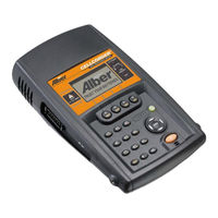
Vertiv Alber Cellcorder CRT-400 User Manual (210 pages)
Battery Analysis System
Brand:
Vertiv
| Category:
Analytical Instruments
| Size: 10.03 MB
Table of Contents
Table of Contents
5
Table of Figures
9
1 General Product Description
19
Safety Information
20
If Questions Come up
20
System Requirements
20
Helpful Reading
21
2 Bas Software Installation
21
Insert BAS Installation CD into PC
21
Figure 1. Insert CD
21
PDF File Program
22
Figure 2. Start|Run
22
Figure 3. Installing When CD Does Not Auto Start
22
Figure 4. BAS Icon
22
Figure 5. Installing the PDF Writer
22
Infrared IR Communication Driver
23
Figure 6. Postscript Interpreter Installation
23
Figure 7. IR Driver Install Window
23
Determine Com Port for IR Communication Driver
24
Figure 8. Select Com Port for IR Communication
24
Figure 9. Install IR Driver
24
3 Start the Battery Analysis Software Bas Program
25
Figure 10. Install IR Driver Later
25
Figure 11. BAS Desktop Icon
25
Understanding the Main Menu Functions
26
Figure 12. BAS Main Window Explained
26
Figure 13. Main Menu Toolbar; File, Analysis, Reports, Device, Help
26
Figure 14. File Drop down Menu
26
Figure 15. Analysis Data Set|Detail| Comparison
27
Figure 16. Reports Data Set|Detail| Comparison| Threshholds
27
Figure 17. Device|Cellcorder| Hydrometer| Communications
27
Figure 18. Analysis Trend|Cells|Cell Averages
27
Figure 19. Reports Trend|Cells|Cell Averages
27
Figure 20. Help
27
Main Menu File|Item
27
Toolbar
28
Toolbar Buttons Explanation
28
Figure 21. Cursor over Toolbar Button with Message
28
Figure 22. Toolbar
28
Comments
30
Figure 23. File|Properties
30
Figure 24. File|Properties|Comments Tab
30
Figure 25. File|Properties|Comments
31
Figure 26. File |Preferences
31
Figure 27. Preferences
31
Status
32
File Types
32
Figure 28. Status Bar
32
Figure 29. Status Bar - Modified - Indicates File Has Been Changed
32
Make Backup Copy of Sample Data
33
Setting Preferences
33
Figure 30. File|Preferences
34
Figure 31. Preferences
34
Figure 32. File|Preferences|Comments Area
34
Figure 33. File New ADF Window
35
Figure 34. Cell Data Pop-Up Window
35
Figure 35. File Import Wizard
35
Communication Setting: Default COM Port
36
Figure 36. Select Cellcorder Window
36
Figure 37. Device|Communications
36
Figure 38. Communication Settings
36
Quick-Check COM Ports PC/BAS
37
Figure 39. Choose Another Communications Port
37
Figure 40. My Computer|Properties
37
Figure 41. System Properties|Hardware
37
Figure 42. System Properties|Hardware|Device Manager
38
Figure 43. Ports (COM & LPT)
38
4 The Important Configuration File Editor
39
Figure 44. BAS Desktop Icon
39
Figure 45. Configure COM Port BAS
39
Figure 46. Configure Appropriate COM Port
39
Multiple Sites - IMPORTANT
40
Figure 47. BAS Desktop Icon
40
Figure 48. File|Configuration Editor
40
General Tab - Configuration Editor
41
Figure 49. Configuration Editor
41
Figure 50. Configuration Editor|File|New| Save|Import|Exit
43
Figure 51. Error Message
43
Figure 52. Configuration Editor|Edit|Delete|Sort
43
Figure 53. Configuration Editor
44
Model Number/Browse/Battery List Editor Window
44
Figure 54. Battery List Editor
45
Figure 55. Import from Another Battery List File
45
Figure 56. Helpful Battlist.blf
46
Figure 57. Www.alber.com Baseline Resistance Data/Battlist.blf
46
Figure 58. BLF on the Website
47
Figure 59. File Download BLF
48
Figure 60. C:\Program Files\Alber\Alber Battery Analysis
48
Figure 61. Imported Battlist.blf
49
Figure 62. File| New Battery
49
Figure 63. Battery List Editor New Battery
50
Threshold Tab - Configuration Editor
51
Figure 64. Threshold Tab
51
Figure 65. File|Properties
52
Figure 66. File|Properties|General Tab|Temp. Scale
52
Type Tab - Configuration Editor
53
Amp Hour Rating
53
Single Testing
53
Figure 67. Configuration Editor Type Tab
53
Dual Testing
54
Triple Testing
54
Quad Testing
54
Combined Testing
54
Computed Testing
54
Figure 68. Saving the CCF
55
The Basics of the Adf: Accumulated Data File
56
Create a New ADF
56
Figure 69. BAS Desktop Icon
56
Figure 70. File|Preferences
57
Figure 71. New File Dialog under File|Preferences
57
Figure 72. File|New
57
Figure 73. New ADF
57
Figure 74. General Battery Information Window
58
Figure 75. Open CDF
58
Figure 76. File| Properties
58
Open|Reopen an ADF for CRT Data
59
Figure 77. File|Properties|General
59
Figure 78. File Open ADF
59
Figure 79. Open an ADF File
59
6 File Properties - Editing Battery Data in the Adf
60
Figure 80. File Reopen Existing ADF
60
Figure 81. File Open ADF
60
General Tab
61
Figure 82. File|Properties
61
Figure 83. File Properties Window |General Tab
61
Details Tab
63
Figure 84. File|Properties|Details
63
Right-Click|Show Threshold Colors
64
Figure 85. Right Click on Details List
64
Figure 86. Show Threshold Colors
64
Right-Click|Set Thresholds
65
Figure 87. Set Thresholds
65
Figure 88. Set Thresholds|Voltage
65
Figure 89. Voltage Display Properties|Threshold
65
Figure 90. Voltage Display Properties|Manual Scale
65
Figure 91. Example Show Threshold Colors Voltage
66
Figure 92. Set Thresholds|Internal Res
66
Figure 93. Internal Resistance Display Properties|Threshold
67
Figure 94. Internal Resistance Display Properties|Manual Scale
67
Figure 95. Example 2
67
Figure 96. Set Thresholds|Intercell Res R1
68
Choosing a Data Set
69
Figure 97. Intercell R1 Display Properties|Threshold
69
Figure 98. Intercell R1 Display Properties|Manual Scale
69
Figure 99. Choose Data Set/Read Date
69
Changing the Read Date
70
Editing Cell Data
70
Figure 100. Right-Click|Modify Read Date
70
Figure 101. Edit Cell Data Value in File Properties Details Tab - Bottom Window in
70
Figure 102. Right-Click Edit
71
Figure 103. Cell Data Grid Editor Changes
71
Configuring Detail Threshold Colors
72
Intertier Tab
72
Figure 104. Intertier Tab|File Properties
72
Figure 105. File Properties|Intertier Tab
73
Figure 106. Configuration Wizard|Intertier Tab|File Properties Window
74
Comments Tab
75
Figure 107. File Properties|Comments Tab
75
Figure 108. Select a New Read Date
75
Create and Use a Template
76
Figure 109. File Properties|Comments Tab Begin Typing
76
Figure 110. Warning to Confirm Comments Template
76
Read Date
76
Create a New Comment for a Read Date
77
Figure 111. Input Template Name
77
6.1.10 Delete a Template Name
78
6.1.11 Delete Comments
78
Figure 112. Use Template Delete Key
78
User-Defined Tab - Properties
79
6.1.12 Create a New User-Defined Field
79
6.1.13 Delete a User-Defined Field
79
Figure 113. File Properties|User-Defined Tab
79
6.1.14 Create New Fields for a Read Date
80
6.1.15 Save as a New Field Template
80
Figure 114. Select a New Read Date
80
7 Specific Methods of Creating Adfs
81
Download a New Data Set from CRT *(.CDF) Via IR
81
Figure 115. New ADF
81
Figure 116. BAS Desktop Icon
82
Figure 117. Create New ADF
82
Figure 118. File New
82
Figure 119. New ADF Window
82
Figure 120. General Battery Information
83
Figure 121. Multi-String Information in the General Battery Information Window
83
Figure 122. Select Cellcorder
84
Figure 123. Do Not Display Cellcorder Screen
84
Figure 124. File Open ADF
85
Figure 125. Align IR Ports
85
Figure 126. Capture
85
Figure 127. Battery Data Capture Create New/Open by Name
86
Figure 128. CRT Battery Data Capture
86
Figure 129. CRT Interface Data Capture/Downloading Data
86
Download a New Data Set from CRT *(.CDF) Via Bluetooth
87
Figure 130. Data Transfer Completed
87
Bluetooth Pair/Connect PC/CRT
88
Figure 131. Laptop
88
Figure 132. BAS Desktop Icon
88
Figure 133. My Bluetooth Places Icon
88
Figure 134. My Bluetooth Places\Entire Bluetooth Neighborhood Window Initial Pairing Bluetooth/Pc
89
Figure 135. CRT
89
Figure 136. Initializing Please Wait (CRT)
90
Figure 137. Wait for Data Transfer Need Better Graphic
90
Figure 138. Search for Devices in Range
90
Figure 139. Pair Device
91
Figure 140. Bluetooth Security Code for Cellcorder Device
91
Figure 141. Paired Cellcorder and PC
91
Figure 142. Bluetooth Connect
92
Figure 143. Record the Bluetooth Serial Port COM
92
Figure 144. Communications Button/Com Port
92
Begin Battery Data Capture Via Bluetooth
93
Figure 145. Serial Port COM
93
Figure 146. CRT
93
Figure 147. Cellcorder Interface Button
93
Figure 148. Select Cellcorder
93
Figure 149. Battery Data Capture
94
Figure 150. Warning Regarding Blank Fields
95
Figure 151. Instructions for CRT
95
Figure 152. CRT
95
Figure 153. Initializing Please Wait CRT
96
Figure 154. Wait for Data Transfer
96
Figure 155. Instructions for CRT
96
Figure 156. CRT Interface Capture
97
Figure 157. Cellcorder Battery Data Capture
97
Figure 158. Warning
98
Figure 159. Transferring Data
98
Capture Hydrometer Data
99
Figure 160. Create New ADF
99
Figure 161. File New
99
Figure 162. New ADF Window from Hydrometer Data Logger
100
Figure 163. File Open ADF
100
Figure 164. Open ADF Window
100
Open|Reopen an ADF for Hydrometer Data
100
Figure 165. File Reopen Existing ADF
101
Figure 166. General Battery Information
101
Figure 167. Instructions for Hydrometer Data Transfer
101
Figure 168. IR Bottom of Data Logger
102
Figure 169. Hydrometer Data Logger Interface Shows Communications: Downloading
102
Figure 170. Successful IR Download
103
Figure 171. Capture Hydrometer Data
103
Hydrometer Data Logger Interface
103
Figure 172. Data Logger Front View
104
Figure 173. Now Click Continue
104
Transfer Data Via RS-232 Port|Cable
104
Figure 174. Hydrometer Interface
105
Capture Data Via IR
106
Figure 175. Hydrometer Data Logger Interface
106
Figure 176. Data Logger Front View
106
Figure 177. Instructions for Hydrometer
107
Figure 178. Battery Data Capture Window
107
Figure 179. Hydrometer Interface
108
Import from DOS-DAT File
109
Figure 180. Create New ADF
110
Figure 181. File New
110
Figure 182. New ADF Window from Cellcorder Data File
110
Figure 183. General Battery Information
111
Figure 184. Select Cellcorder
111
Figure 185. File Import Wizard
112
Figure 186. File Import Wizard Step 1. DOS Data File Window
112
Figure 187. Step 2. Browse for DOS *.Dat File
113
Figure 188. Navigate to DOS *.Dat Files
113
Figure 189. Open DOS File
113
Figure 190. Step 2. DOS *.Dat Import
114
Figure 191. Step 3. Finish DOS File Import
114
Figure 192. File Reopen Existing ADF
114
Figure 193. USB Flash Hard Drive Inserted into CRT
115
Figure 194. USB Flash Hard Drive Inserted into PC
115
Open CRT Data (*.CDF) File on USB Device
115
Figure 195. BAS Desktop Icon
116
Figure 196. File|Open|Cdf
116
Figure 197. Removable Disk: USB Device
116
Figure 198. Removable Disk: USB Device
116
Figure 199. Open a CDF from the USB Device
117
Figure 200. Configuration Information to be Imported
117
Create an ADF Manually
118
Figure 201. Confirmation Import CDF| Create New|Import to Existing
118
Figure 202. Import File Confirmation
118
Figure 203. File New Button
118
Figure 204. File|New
118
Figure 205. New Adf|Manual Data Set
119
Figure 206. General Battery Information
119
Figure 207. Read Date
119
Figure 208. File Properties Details
120
Figure 209. Cell Data Grid Editor
120
Figure 210. File Properties Details Tab
120
Figure 211. File Properties Details Cell|Right Click Functionality
121
Figure 212. Save ADF
121
Figure 213. File Properties|Details|New Data Set
121
Figure 214. New Data Set Read Date Window
122
Figure 215. File Properties|Delete Data Set
122
Figure 216. Warning Ask for Confirmation on Delete
122
File Search Tool: Search for Files
123
File Name Tab
123
Figure 217. File|Search
123
Figure 218. File Search Tool Window| File Name Tab
123
Figure 219. File Search Tool
124
Figure 220. Search|Look in
124
Figure 221. Browse
124
Buttons|Tabs Explained
125
Figure 222. ADF Parameters & User Defined Tabs
125
Description Tab
126
Dates Tab - Install Date, Read Date
126
Figure 223. File Search|Description Tab
126
Parameters Tab (ADF Files Only)
127
Figure 224. File Search|Dates Tab|Install|Read
127
Figure 225. File Search|Parameters Tab
127
Figure 226. Parameter Search Criteria
128
User-Defined Window - Search
129
Figure 227. User-Defined Search Window
129
9 Managing Battery Data Files/Adf
130
Figure 228. File Search Report Setup
130
Figure 229. File Extract or File Merge
130
Saving Battery Files
131
Figure 230. Save the Current File
131
Figure 231. File Save/Save as
131
Figure 232. Status = Modified ADF
131
Figure 233. Directory Structure
132
Extracting Data Sets
133
Figure 234. File Extract
133
Figure 235. Extract Data Window
133
Figure 236. Scratch File
134
Figure 237. Extract Data to Existing ADF
134
Figure 238. Warning Window Duplicate Date Options
135
Figure 239. Extract Data Set Comments Destination File
135
Merging Data Sets
136
Figure 240. File Merge
136
Figure 241. File to Merge Data from
137
Figure 242. Merge File Query Duplicate Read Date
137
10 Data Analysis - Viewing Data and Graphs
138
Figure 243. Main Menu > Analysis|Data Set|Detail
138
Figure 244. Select Strings
138
Figure 245. Undo Zoom
138
Display Cell Data Within a Bar Graph
139
Figure 246. Data Set Detail Graph
139
Figure 247. Graph Bar|Cell Data
139
Graph Menus Explained
140
Figure 248. Graph Bar|Cell Data Bold Value Explained
140
Figure 249. Graph Menus
140
10.1.1 Graph or Table
141
10.1.2 Point Labels
141
10.1.3 Point Frequency
141
10.1.4 Shadows
141
10.1.5 Titles
141
10.1.6 Maximize
141
10.1.7 Zoom and Undo Zoom
141
Print the Graph
142
10.1.8 Print
142
10.1.9 Export
142
Exit
142
Parameters Menu Explained
142
Trend
142
Figure 250. Parameters Menu
142
Figure 251. Main Toolbar|View Battery Cell Trend Graphs
142
Comparison
143
Edit
143
Figure 252. Main Menu|Analysis|Trend
143
Figure 253. Parameters|Comparison
143
Figure 254. Parameters|Edit
143
Figure 255. Cell Data Editor
143
Thresholds
144
Figure 256. Parameters|Thresholds
144
Figure 257. Parameters|Thresholds
144
Figure 258. Display Properties
144
10.1.14.1 Setting Threshold Levels/Color Indicators
145
Figure 259. Threshold Colors for Bar Graphs
145
10.1.14.2 Setting Parameters|Thresholds|Scale
146
Figure 260. Parameters|Thresholds|Scale
146
Subsets
147
Figure 261. Voltage Only Subset
147
Figure 262. Graph with Voltage Only Subset Chosen
147
Figure 263. All Subsets Chosen
148
Figure 264. Graph with All Subsets Chosen
148
Comparison Graph Display
149
Figure 265. View Battery Data Set Graphs
149
Figure 266. Parameters|Comparison
149
Figure 267. Data Set Read Date for Comparison Graph
149
Figure 268. Graph|Set as Reference
150
Figure 269. Select Date to Compare with Reference Data Set
150
Figure 270. Comparison Graph Example
151
Figure 271. Comparison Data Set Graph Example 3/14/2003
151
Figure 272. Reference Data Set Example 10/04/1996
151
Trending a Parameter over Time
152
Figure 273. Open File with Multiple Data Sets
152
Figure 274. View Graph
152
Figure 275. Click Cell in Graph
153
Figure 276. Parameters|Trend|Cells
153
Figure 277. Select Parameters
154
Figure 278. Data Subset Internal Resistance Only
154
Figure 279. Clearing Selected Subsets
154
Figure 280. Cell 52 from the Sample File Demo-60 Cell Hydro Plant Battery
155
Trending a Parameter Average over Time
156
Figure 281. Open File with Multiple Data Sets
156
Figure 282. View Graph
156
Figure 283. Click Cell in Graph
157
Figure 284. Parameters|Trend|Cell Averages
157
Figure 285. Battery Cell Averages Trend Graph
158
Figure 286. Cell Average Trend Data
158
11 Generating Reports: Five Report Types
159
Figure 287. Main Menu|Reports|Data Set
159
Figure 288. Main Menu|Trend
159
Figure 289. Main Toolbar|Create a Dataset Detail Report
159
Figure 290. Buttons at Top of Reports
160
Each Report Type Has Five Setup Tabs
161
Figure 291. Save Report as Text
161
Figure 292. Reports and Report Setup Tabs
161
11.1.1 Data Sets Tab
162
11.1.2 Strings|Cells Tab
162
11.1.3 Graphs and Tables Tab for All Reports but Threshold
162
Figure 293. File|Properties
162
11.1.4 Reports|Data Set|Thresholds Graphs and Tables Tab
163
11.1.5 User Defined Tab
163
11.1.6 Other Options Tab All Reports
163
11 Generating Reports: Five Report Types
147
Detail Report
163
Figure 294. Reports|Data Set|Detail
163
Figure 295. Data Sets Tab
164
Figure 296. Strings/Cells Tab
164
Figure 297. Graphs and Tables Tab
165
Figure 298. User Defined Fields to be Included
165
Figure 299. File| Properties|User Defined Tab/Field Name/Contents
166
Figure 300. Other Options Tab
166
Figure 301. Data Set Detail Report Examples
167
Comparison Report
168
Figure 302. Data Set Graph on Detail Report
168
Figure 303. Reports|Data Set|Comparison
169
Figure 304. Select Reference Data Set and Comparison Data Sets
169
Figure 305. Select Strings for the Comparison Report
169
Figure 306. Comparison Report Setup Graphs and Tables Tab
170
Figure 307. User Defined Tab in Comparison Report Setup
170
Figure 308. Other Options Tab Comparison Report Setup Window
170
Figure 309. Data Set Comparison Report/Graph Examples
171
Threshold Deviation Report
172
Figure 310. Other Options Tab Comparison Report Setup Window
172
Figure 311. Threshold Report Setup Choose Data Sets
172
Figure 312. Select Strings for Threshold Report
172
Figure 313. Threshold Report Graphs and Tables Tab
173
Figure 314. User Defined Fields
173
Figure 315. Other Options Tab for the Threshold Report
173
Figure 316. Threshold Report with Graphs Example
174
Cell Trend Report
175
Figure 317. Reports|Trend|Cells
175
Figure 318. Reports|Trend|Cells|Data Sets Tab
175
Figure 319. Reports|Trend|Cells |String/Cells Tab = Multi String Left Unselected in
175
Figure 320. Reports|Trend|Cells |String/Cells Tab = Multi String Selected in Properties157 Figure 321. Reports|Trend|Cells |Graphs and Tables Tab
176
Figure 322. Reports|Trend| Cells|User Defined
176
Figure 323. Reports|Trend|Cells|Other Options Tab
176
Cell Averages Trend Report
177
Figure 324. Battery Cell Trend Graph
177
Figure 325. Reports|Trend|Cell Averages
177
Figure 326. Reports|Trend|Cell Averages|Data Sets Tab
178
Figure 327. Reports|Trend|Cell Averages|Strings/Cells Tab = Multi String in Properties Left Unselected
178
Figure 328. Reports|Trend|Cell Averages|Strings/Cells Tab = Multi String in Properties Selected
178
Figure 329. Reports|Trend|Cell Averages|Graphs and Tables Tab
179
Figure 330. Reports|Trend|Cell Averages|User Defined Tab
179
Figure 331. Reports|Trend|Cell Averages|Other Options Tab
180
Figure 332. Cell Average Trend Report
180
Print to PDF
181
Figure 333. Cell Average Trend Graph
181
Figure 334. User Defined Data and Other Options Information Can be Found at the
181
Archive Reader
182
Figure 335. Main Menu Reports|Load
182
Figure 336. Start|Programs|Alber|Alber Battery Analysis| Archive Reader
182
12 Exporting Graph Data: Options
183
Figure 337. Graph Export Data
183
Figure 338. Excel Export Option
183
Microsoft Excel
184
DOS DB File
184
Others; Metafile, BMP, Text/Data Only
184
Figure 339. DOS DB Export Option
184
Figure 340. Other Graph Export Options
184
Figure 341. Exporting String 1
184
Exported Data's Destination
185
12.1.1 Clipboard
185
12.1.2 File
185
12.1.3 Print Metafile Only Pr
185
How Selecting a File Type Influences Output
185
12.1.4 Metafile
185
12.1.5 Bmp
185
12.1.6 Text|Data
185
Figure 342. File Type Export Outputs
185
Figure 343. Graph Export Text/Data Only
186
Figure 344. Export Text|Data Options
186
12.1.6.1 Select Subsets and Points
187
12.1.6.2 Export What
187
12.1.6.3 Export Style
187
Figure 345. Graph's Text Data Without Labels
187
Figure 346. Graph's Text Data and Labels with y Axis Value Selected
187
Figure 347. Graph's Data and Labels with Point Number, y Axis Value Selected
187
Figure 348. Tab Format
188
Figure 349. Column Format
188
Figure 350. Table Subset by Point Format
188
Figure 351. Table Point by Subset Format
188
13 CRT Data Backup
189
Memory Card Note
189
14 Upgrading CRT Firmware
190
Figure 352. Www.alber.com/Softwareupdates.htm
190
Upgrade Via USB Device/Crt-400S
191
Figure 353. System Is Ready
191
Figure 354. System Is Ready
191
Figure 355. Sytem Ready for Upgrade
191
Upgrade Using the IR Port
192
Figure 356. Preparing Memory for Memory
192
Figure 357. File Transfer in Process
192
Figure 358. Upgrade Successful
192
Figure 359. Www.alber.com/Softwareupdates.htm
193
Figure 360. System Is Ready
193
Figure 361. System Is Ready
194
Figure 362. Sytem Ready for Upgrade
194
Figure 363. Preparing Memory for Memory
194
Figure 364. File Transfer in Process
194
Figure 365. Communications Settings Com Port BAS Software
195
Figure 366. BAS Software Program Select Cellcorder
195
Figure 367. Bas/Instructions
196
Figure 368. Align IR Ports
196
Figure 369. BAS/CRT Interface Window
196
Figure 370. Open *.UPG File
197
Figure 371. File Transfer in Process
197
Figure 372. Upgrade Successful
197
Upgrade Via Memory Card/Crt-300S
198
180
198
Capturing CLC-200 Battery Data
198
Figure 373. BAS/CRT Interface Window
198
15.1.1 a New ADF for CLC-200 Data
199
15.1.2 Capturing CLC-200 Data
199
CLC-200 Calibration Backup
202
15.1.3 Backup Via Serial Cable
202
15.1.4 Restore Via Serial Cable
203
Upgrading CLC-200 Firmware
203
15.1.5 Upgrade Via Serial Cable
203
16 Index
205
Advertisement
Vertiv Alber Cellcorder CRT-400 User Manual (152 pages)
Brand:
Vertiv
| Category:
Test Equipment
| Size: 5.62 MB
Table of Contents
Table of Contents
3
Safety Information
10
General
10
Document Symbols
10
Safety Symbols
11
Product Safety Practices
11
Preventive Maintenance
13
Visual Inspection
13
Cleaning System Components
13
Internal Component Replacement
13
Shipping, Storage, Normal Use Protection
13
Product Overview
14
BAS Software
14
Cellcorder Serial Number
14
Features
14
Figure 1 - Serial Number Location and Label
15
Figure 2 - Cellcorder Right Panel Connector/Infrared
15
Figure 3 - Cellcorder Left Panel Connector/Test Lead and USB
16
Cellcorder CRT-400
18
Panel Controls and Indicators
21
Figure 4- CRT Front Panel Diagram Left
21
Figure 5 - CRT Front Panel Diagram Right
22
Figure 6 - Top Panel LED Indicators
23
Figure 7 - Keypad
23
Figure 8 - Trans-Reflective LCD Display
25
Figure 9 - Top Panel Controls, F1, F2, F3, and F4
25
Figure 10 - Back Panel/Telco/Reset Switch/Power
27
Specifications
28
Table 1 - Back Panel/Telco/Reset Switch/Power
29
Before Using the CRT-400
30
Highly Recommended Reading
30
Charging the Cellcorder Battery
30
Figure 11 - Green LED Charge Indicator
30
Test Lead Connection Practices
32
Understanding the USB Port and Flash Hard Drive
32
Figure 12 - USB Device
33
Figure 13 - My Computer/Eject
33
Figure 14 - Safely Remove Hardware Window
34
Figure 15 - Confirmation to Stop Hardware Device
34
Understanding Bluetooth
35
Getting Ready to Test Batteries with the CRT-400
36
Power
36
Basic Main Menu Functions
36
Figure 16 - CRT-400 Main Menu on LCD with F1, F2, F3 and F4 Buttons
36
Table 2 - Function Buttons
36
Figure 17 - CRT-400 F1, F2, F3 and F4 Buttons
37
Navigation
38
The Baseline Resistance Data File on USB
38
Insert the USB Device into the CRT
38
Figure 18 - CRT-400 Power and Arrow Buttons
38
How to Edit Items Within the Site Template
39
Figure 19 - CRT-400 with USB Flash Hard Drive
39
Figure 20 - CRT-400 Keypad Buttons
40
Figure 21 - CRT-400 Load Data Functions
40
Table 3 - CRT-400 Keypad Buttons
42
Deselecting a Site
43
Next Steps, Battery Selection
43
Figure 22 - Deselecting a Site
43
Figure 23 - CRT Set up
44
Figure 24 - CRT Test Mode
44
Taking Float Voltage Readings First
46
Figure 25 - Connect Voltage Test Leads
46
Figure 26 - CRT - Test Mode
46
F4/Done Voltage Testing
47
Stored in Memory Explained
47
Figure 27 - Placement of Probes on Cells
47
Resume Testing Explained
48
Setting up to Take Resistance Readings
49
Figure 28 - Resistance Test Lead Assembly Clamps
49
Figure 29 - Insert Resistance Test Leads Left Side CRT
49
Figure 30 - CRT-Test Mode/F1
50
Check/Set Amp Hours
51
Set Intercell Connections
51
Figure 31 - Quad Testing
52
Taking Resistance Readings
53
Resistance Readings
53
Figure 32 - CRT-Test Mode/F1
53
Connecting Resistance Test Leads
54
Connection for Single Intercell Connectors
54
Figure 33 - Single Intercell Connectors
54
Connection for Dual Post Cells - Example One
55
Figure 34 - Connections for Dual Post Cells - Example One
55
Connection for Dual Post Cells - Example Two
56
Figure 35 - Connections for Dual Post Cells - Example Two
56
Connections for Triple Post Cells
57
Figure 36 - Connections for Trip Post Cells - One
57
Figure 37 - Connections for Trip Post Cells - Two
57
Performing a Resistance Test
58
Figure 38 - Connections for Trip Post Cells - Three
58
Moving Probes from Cell to Cell
59
When no Float Voltages Exist
60
Understanding Voltage Skewing Effect
61
Using the CRT-400 as a Digital Voltmeter
62
Figure 39 - CRT-Test Mode/F1
62
The Hydrometer and the Data Logger
63
Figure 40 - Hydrometer, Data Logger, PC, CRT, USB Interaction
63
Setting up the CRT for Hydrometer Usage
64
Figure 41 - CRT-CRT Setup/F4
64
Taking Readings with the Hydrometer
66
Figure 43 - CRT-Main Menu/Load Data/F3
66
Transferring Hydrometer Data to Computer
68
Figure 44 - Data Logger
68
Setting up the CRT
69
Figure 45 - CRT-Main Menu with F Buttons for CRT Setup/F4
69
Selecting a Battery
70
Reading USB
70
Selecting a Manufacturer
70
Selecting a Model
70
Figure 46 - CRT- Setup/Bat. Select-F4
70
Setting Thresholds
71
Setting Thresholds Without a Site File
72
Clearing Memory
74
Figure 48 - CRT Setup/Clear Memory or F4/F3
75
Displaying Additional Functions
76
Figure 49 - CRT Setup/Display Functions
76
Sound Adjustment
77
Frequency
77
Figure 50 - CRT Sound Adjustment
77
Figure 51 - CRT AC Line Frequency 50/60 Hz
77
Adjusting Date and Time
78
Reserved
78
Setting up Bluetooth Wireless Communication
78
Figure 52 - CRT Time and Date
78
Setting up and Editing a Site Template
85
Figure 53 - CRT Load Data Main Menu
85
Table 4 - Editing a Site Template
87
Figure 54 - CRT Load Data Main Menu
88
Figure 55 - CRT Clear/F3/Deselect a Site
89
Figure 56 - CRT Main Menu on Lcd/Load Data
90
Figure 57 - CRT Main Menu on Lcd/Load Data
91
Figure 58 - CRT Main Menu on Lcd/Load Data
92
Figure 59 - CRT Main Menu on LCD/LOAD DATA
96
Working with Files
98
Saving Readings and Files to the USB Flash Hard Drive
98
File Types Located on the USB Flash Hard Drive
99
Figure 60 - Www.vertivco.com/Baseline Resistance Data
101
Figure 61 - Snapshot Baseline Resistance Data
101
Figure 62 - File Download Window
102
Figure 63 - Saving BLF File
102
Figure 64 - My Computer ICON
103
Figure 65 - My Computer/Eject
103
Figure 66 - Safely Remove Hardware Window
104
Figure 67 - Confirmation to Stop Hardware Device
104
Figure 68 - Safe to Remove Hardware Device
104
Figure 69 - CRT Main Menu on Lcd/Load Data
105
Appending to an Existing File
106
Storing Data for Multiple Strings
108
Deleting a File from the USB Flash Hard Drive
108
Figure 70 - CRT Main Menu on Lcd/Load Data
108
Sending Readings Via IR
109
Figure 71 - BAS Software Program Select Cellcorder
110
Figure 72 - BAS/CRT Interface Window
111
Figure 73 - Bas/Battery Data Capture Open or Create New File
111
Figure 74 - Bas/Cellcorder Battery Data Capture
111
Sending Readings Via Bluetooth Wireless
112
Figure 75 - BAS/CRT Interface Data Transfer Completed
112
Figure 76 - BAS Software Program Select Cellcorder
113
Figure 77 - BAS/CRT Interface Window
113
Figure 78 - Bas/Battery Data Capture Open or Create New File
114
Figure 79 - Bas/Cellcorder Battery Data Capture
114
Figure 80 - BAS/CRT Interface Data Transfer Completed
115
Viewing Results
117
Viewing Status
117
Viewing the Overall Voltage Data
117
Figure 81 - View Results/F2-Faults/F3
118
Using Diagnostics
120
Testing Keypad
120
A/D Linearity
122
Utilizing CRT-400 Service Menu
124
Entering the Password
124
Changing the Password
126
Error Codes
127
Battery Maintenance Schedule
127
Table 5 - Battery Maintenance Schedule
127
Upgrading Firmware
128
Figure 82 - Communications Settings Com Port BAS Software
130
Figure 83 - BAS Software Program Select Cellcorder
130
Figure 84 - BAS/CRT Interface
131
Figure 85 - BAS/CRT Interface Window
132
Application Note CC-001
133
Figure 86 - Valve Regulated and Vented Cells
133
Figure 87 - Classical Cell Model
134
Figure 88 - Internal Resistance Model
135
Figure 89 - Capacity and Internal Resistance Ratio
136
Figure 90 - Typical Discharge Curve of a 100% Capacity Cell
136
Figure 91 - Typical Discharge Curve with Metallic Resistance Problem
137
Figure 92 - Typical Discharge Curve with a Cell with an Electrochemical Resistance Problem
138
Figure 93 - Normalized Internal Resistance Vs. Temperature
139
Figure 94 - Measuring Internal Resistance
140
Application Note CC-002-A
145
Figure 95 - Single Interconnections
146
Figure 96 - Contacting Tips to Posts (Fig. 2A and Fig. 2B)
146
Figure 97 - (Figure 3A and 3B) Connections for Dual Posts
147
Figure 98 - (Figure 4) Connections for Triple Posts
148
Figure 99 - (Fig 5) Connections for Triple Posts
148
Cellcorder Connection Options
149
Figure 100 - CRT-400 Cellcorder Connection Options
149
Cellcorder Jaw Options
150
Figure 101 - CRT-400 Cellcorder Jaw Options
150
Index
151
Vertiv Alber Cellcorder CRT-400 Previewer User's Manual (62 pages)
Brand:
Vertiv
| Category:
Test Equipment
| Size: 2.37 MB
Table of Contents
Table of Contents
5
1 General Product Description
9
Safety Information
9
If Questions Come up
9
System Requirements
9
Helpful Reading
10
2 Bas Software Installation with Crt Previewer
10
Insert Bas/Previewer Installation CD into PC
11
PDF File Program
11
Figure 1. Insert CD
11
Figure 2. Start|Run
11
Figure 3. Installing When CD Does Not Auto Start
11
Figure 4. Previewer Icon
11
Infrared IR Communication Driver BAS USAGE ONLY
12
Figure 5. Installing the PDF Writer
12
Figure 6. Postscript Interpreter Installation
12
Determine COM Port for IR BAS USAGE ONLY
13
Figure 7. IR Driver Install Window
13
Figure 8. Select COM Port for IR Communication BAS USAGE ONLY
13
Figure 9. Install IR Driver/Bas USAGE ONLY
14
3 Start Previewer Software
15
Explanation of File Types
15
Figure 10. Install IR Driver Later/Bas USAGE ONLY
15
Figure 11. Start|Programs|Vertivco|Vertivco Battery Analysis| CRT Previewer
15
Make Backup Copy of Sample Data
16
Understanding the Main Menu Functions
16
Figure 12. Main Menu; File, Graph & Help
16
Figure 13. Main Menu File
17
Figure 14. Main Menu Help
17
Figure 15. Main Menu Graph
17
Figure 16. File Menu
18
File
18
Figure 17. Main Menu Graph
19
Figure 18. Return to Previous Graph View Esc Key
19
Graph
19
Figure 19. Main Menu Help
20
Figure 20. Help on Help Window and Explanation
20
Figure 21. Help about
20
Help
20
Toolbar
21
Previewer Tabs
21
General
21
Figure 22. Toolbar
21
Figure 23. General Tab
22
Tabular Data
23
Figure 24. Tabular Data Tab
24
Figure 25. Tabular Data Sort Ascending
25
Figure 26. Tabular Data Sort Descending
25
Graph
26
Figure 27. Cell Data Editor
26
Figure 28. Graph Tab
27
Intertier
28
Figure 29. Select Parameter
28
Figure 30. Cell Data Box
28
Figure 31. Intertier Tab
29
Comments
31
4 The Important Configuration File Editor: Ccf
31
Figure 32. Comments Tab
31
Multiple Sites - IMPORTANT
32
Figure 33. Previewer Icon
32
Figure 34. File|Configuration Editor
32
General Tab - Configuration File Editor CFE
33
Figure 35. Configuration Editor
33
Figure 36. Configuration Editor|File|New| Save|Import|Exit
35
Figure 37. Error Message
35
Figure 38. Configuration Editor|Edit|Delete|Sort
35
Figure 39. Configuration File Editor
36
Model Number/Browse/Battery List Editor Window
36
Figure 40. Battery List Editor
37
Figure 42. Helpful Battlist.blf
38
Figure 44. BLF on the Website
39
Figure 45. File Download BLF
40
Figure 47. Imported Battlist.blf
41
Figure 49. Battery List Editor New Battery
42
Threshold Tab - Configuration Editor
43
Amp Hour Rating
44
Single Testing
44
Test Mode Tab - Configuration Editor
44
Combined Testing
45
Computed Testing
45
Dual Testing
45
Quad Testing
45
Triple Testing
45
5 Begin - Open a *.Cdf or View Crt Battery Data
46
To Save Readings/Files (from CRT Manual)
47
Figure 57. File|Open
48
Memory Card Note
49
6 Generating Reports
50
Setting Report Options
50
7 Exporting Data
51
Export File Type
52
Export Destination
52
Figure 63. Export Text
53
8 Creating a Data Set
55
9 Crt Calibration Backup
55
10 Crt Calibration Backup
56
11 Upgrade CRT Firmware
58
Advertisement
Vertiv Alber Cellcorder CRT-400 Operating Instructions Manual (6 pages)
Cell Resistance Tester
Brand:
Vertiv
| Category:
Circuit Tester
| Size: 11.3 MB
Advertisement
Related Products
Vertiv CR030
Vertiv CR060
Vertiv Liebert CR025
Vertiv Liebert CR045
Vertiv Liebert CRV CRD101-0D00A
Vertiv Liebert CRV CRD102-1D00A
Vertiv Liebert CRV CRD25
Vertiv Liebert CRV CCD25
Vertiv Liebert CRV300
Vertiv Liebert CRV 300 CW
Vertiv Categories
UPS
Power Supply
Switch
Power distribution unit
Air Conditioner
More Vertiv Manuals
Login
Sign In
OR
Sign in with Facebook
Sign in with Google
Upload manual
Upload from disk
Upload from URL