Sign In
Upload
Manuals
Brands
Vertiv Manuals
Power Supply
581127000
Vertiv 581127000 Manuals
Manuals and User Guides for Vertiv 581127000. We have
1
Vertiv 581127000 manual available for free PDF download: Installation Manual
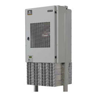
Vertiv 581127000 Installation Manual (142 pages)
+24V DC Power System
Brand:
Vertiv
| Category:
Power Supply
| Size: 12.41 MB
Table of Contents
Table of Contents
3
Admonishments Used in this Document
5
Important Safety Instructions
6
General Safety
6
Voltages
6
AC Input Voltages
6
DC Output and Battery Voltages
6
Battery
7
Personal Protective Equipment (PPE)
8
Hazardous Voltage
8
Handling Equipment Containing Static Sensitive Components
8
Maintenance and Replacement Procedures
8
Static Warning
9
Customer Documentation Package
11
Installation Acceptance Checklist
11
Installing the System
13
General Requirements
13
Securing the Relay Rack to the Floor
14
Mounting System Components in an Equipment Rack
18
Mounting the Distribution Cabinet with Module Mounting Assembly
18
Installing a 581127000 List 93 Battery Tray
21
Installing Optional Battery Busbar Extension Kit, Part No. 562364
25
Installing Optional Lug Adapter Busbar Kits, Part Nos. 534449 and
27
Installing Optional Lug Adapter Busbar Kit, Part No. 562888
29
Installing Circuit Breakers and Fuses
31
Setting Jumpers and Switch Options
44
Circuit Card Locations
44
Jumpers on System Interface Circuit Card
45
Switch Settings on IB2 Interface Board
47
Switch Setting on Optional EIB Interface Board
47
Switch Setting on SM-DU
50
Making Electrical Connections
52
Important Safety Instructions
52
Wiring Considerations
52
Relay Rack Grounding Connection (Frame Ground)
53
Central Office Ground Connection
53
AC Input and AC Input Equipment Grounding Connections
55
External Alarm, Reference, Monitoring, and Control Connections
68
Circuit Card Locations
68
System Interface Circuit Card
69
IB2 (Controller Interface Board) Connections (if Required)
71
Required)
76
Optional SM-DU+ and Shunt Interface Board
82
Connecting a Device or System to the Controller's CAN Bus
84
Controller Ethernet Connection (if Required)
85
Shelves
90
Connecting Converter Output Cables 581127000 List 60
92
Load Connections
95
Recommended Torques
95
Load Connections to Single Voltage Distribution Panels
96
Load Connections to Dual Voltage Distribution Panels
101
Load Connections to Return Bar
106
Load Connections to Bulk Output Panel
106
Load Connections to GMT Distribution Fuse Block
107
Battery Connections
108
Important Safety Instructions
108
Recommended Torques
108
Panels
108
Battery Connections to Distribution Cabinet Battery Busbars
112
Battery Connections to Optional Battery Busbar Extension Kit P/N
114
Battery Connections to Optional Battery Landing Busbar Kit P/N
115
Installing and Connecting Batteries in List 93 Battery Tray
117
Furnished)
117
Installing the Rectifier and DC-DC Converter Modules
125
Initially Starting, Configuring, and Checking System Operation
127
Initial Startup Preparation
127
Initially Starting the System
127
ACU+ Controller Procedure
127
NCU Controller Procedure
134
Checking System Status
139
Final Steps
140
Advertisement
Advertisement
Related Products
Vertiv 581126000
Vertiv NetSure 582136700SK002
Vertiv 582127000101
Vertiv 582127000103
Vertiv 582127000503
Vertiv 582127200
Vertiv 582127000502
Vertiv 582127000501
Vertiv 582127000500
Vertiv 582127000102
Vertiv Categories
UPS
Power Supply
Switch
Power distribution unit
Air Conditioner
More Vertiv Manuals
Login
Sign In
OR
Sign in with Facebook
Sign in with Google
Upload manual
Upload from disk
Upload from URL