Sign In
Upload
Manuals
Brands
Vertical Express Manuals
Controller
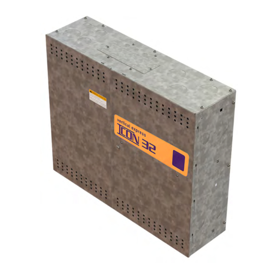
ICON 32
Vertical Express ICON 32 Manuals
Manuals and User Guides for Vertical Express ICON 32. We have
1
Vertical Express ICON 32 manual available for free PDF download: Product Manual
Vertical Express ICON 32 Product Manual (220 pages)
Brand:
Vertical Express
| Category:
Controller
| Size: 16 MB
Table of Contents
Table of Contents
5
Preliminary Installation
7
Prepare for Temporary Operation
7
Configure the UPS
9
Temporary Operation
10
Runbug Set up
10
Electronic Starter Setup
14
Mechanical Starter Set up with ESP200 Overloads
15
Pump Motor Rotation
17
I-2/I-3 Valve
18
Relief Pressure Verification
19
Low Pressure Adjustment
19
Selector Tape
21
Mount the Tape
21
Hoistway Wiring
24
Wireway and Conduit Layout
25
Typical Hoistway Conduit/Duct Layout
26
Typical Front Conduit/Duct Layout
27
Typical Rear Conduit/Duct Layout
28
Interlock Wiring
29
Traveling Cable Installation
31
Hoistway Entrance Frames and Doors
32
Cab
32
Door Operator
32
Selector Box Mounting and Alignment
32
Formed Rail Selector Box
33
T-Rail Selector Box
34
Twin Post Selector Box
35
Tape Selector Bolt Kit for Crosshead Mount (200BWY001)
36
Car Top Wiring
37
Swing Return Wiring
38
Machine Room Wiring
38
Table of Contents
41
Preliminary Adjustment
43
Remove Temporary Operation
43
User Interface Tool (UIT) Menu Tree
45
Software Verification Procedure
46
Safety Processor Verification
47
Configure the Safety Processor
48
CAN Node Address Assignment
48
Verify Proper Resistive Loading for the CAN Channels
51
CAN Node Configuration Via the Startup Wizard
53
I/O and Safety String Checkout
54
Troubleshooting I/O Issues
57
Car Top Inspection Operation
57
Selector Tape Magnet Installation
58
Selector Tape and Box Inspection
58
Magnet Placement
58
Preliminary Setup for Automatic Operation
65
Hoistway Scan through the Startup Wizard
65
Door Setup and Final Adjustments
66
I-2/I-3 Valve - Final Adjustments
67
Valve Adjustment up Section
68
Valve Adjustment down Section
69
Performance Check with Full Load
73
Final Relief Pressure with Full Load
73
Floor Position & Leveling Magnet Adjustment
74
Terminal Slowdown Check
75
Verify Proper Function of the up Terminal Slowdown Magnets Via the UIT
75
Verify Proper Function of the down Terminal Slowdown Magnets Via the UIT
76
Final Adjustments
77
ESP200 Overload
77
Electronic Starter
78
Operational Adjustments
79
Configure the THY02 Card
79
Additional Operational Adjustments
80
Save Parameters and Backup Job Software
81
Table of Contents
85
Adjustments
87
Commands
103
Inputs and Outputs
105
No Known Application Rule I/O
113
Control System Fault Codes
117
SP Fault Codes - Safety Processor
127
NP Fault Codes - NTSD Processor
129
WPT Diagnostics
130
Table of Contents
133
Controller CAN System Overview
135
Configure the CAN Nodes
136
CAN Node Address Assignment
136
CAN Channel Resistive Loading Verification
139
Car CAN Channel 2
139
Hall CAN Channel 3
140
Group CAN Channel Termination
141
CAN Channel Troubleshooting Guide
142
Correct an Offline CAN Node
143
Ping a CN Port
144
Troubleshooting I/O Issues
145
I/O Reference Table
145
Troubleshooting Guide
147
CE Microcomm Troubleshooting
149
Motor Data for Siemens Electronic Starter
150
Transformer Configuration Data
151
IOF Card (6300AHV001)
152
IOF - LED Definitions
153
IOF - Shunt Jumper Definitions/Settings
154
IOF - con Jumper Definitions/Settings
154
IOF - Push Buttons and Switches
154
IOF Fuses
154
IOF Connectors/Wiring
155
CPUC Card (6300AHT001)
156
CPUC - LED Definitions
157
CPUC - Connectors
157
CPUC Shunt Jumper Definitions and Settings
158
CPUC Power Supply Tolerances
158
CPUC Switch Functions
158
CAN Node - LED Definitions
158
CAN Node Jumpers
159
LHV Jumpers
160
L24/LHV/S24-1/S24-2 Cards
161
CAN Selector Leds
162
On-Card Diagnostics
152
Table of Contents
167
Replacement Parts
169
Controller Assembly (2102BB)
169
Power Panels
170
Controller Assembly (2102BB) - Replacement Parts List
172
Freight Door Cabinet Assembly (2104AF)
174
Manual Freight Door Cabinet Assembly (2104BL)
175
Fire Service Cabinet (2104AE)
177
Selector Assembly (2105AG)
178
Replacement Sensors
179
Cards and Fuses
180
Replacement Part Numbers
185
Controller User Interface Tool (UIT)
186
Primary Menus
186
Access the UIT
186
UIT Menu Tree
187
CAN Node Configuration Via the Startup Wizard
188
CAN Nodes
188
Command Sequence
189
Card Changing Procedures
191
Door Card
191
CAN Node Card
191
L24, S24-1, S24-2, LHV, LHV 4X4 Cards
191
TSMC/TSAC Card
192
IOF Card Changing Procedure
192
CPU Replacement
195
Software Management
197
Software Version Confirmation
197
How to Format a USB Flash Drive
198
USB Flash Drive Preparation
200
Backup the Job Software
201
Upload Software to CPU Cards
202
Upload Software Troubleshooting
203
Software Updates to Safety Node Devices over CAN
203
Configure the Safety Processor
204
Networking
204
UIT Menu Tree
209
Cable Connections
210
CNA Fixed I/O Charts
213
ICON32 I/O Chart
214
I-2/I-3 Valve Reference
215
Advertisement
Advertisement
Related Products
Vertical Express I-2
Vertical Express I-3
Vertical Express Categories
Door Opening System
Garage Door Opener
Control Unit
Elevators
Controller
More Vertical Express Manuals
Login
Sign In
OR
Sign in with Facebook
Sign in with Google
Upload manual
Upload from disk
Upload from URL