Sign In
Upload
Manuals
Brands
VAT Manuals
Control Unit
650 GS Series
VAT 650 GS Series Manuals
Manuals and User Guides for VAT 650 GS Series. We have
2
VAT 650 GS Series manuals available for free PDF download: Installation, Operating, & Maintenance Instructions
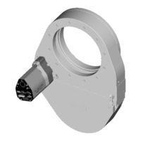
VAT 650 GS Series Installation, Operating, & Maintenance Instructions (94 pages)
Pendulum control & isolation valve with CC-Link interface with valve cluster functionality
Brand:
VAT
| Category:
Control Unit
| Size: 3 MB
Table of Contents
Table of Contents
3
Use of Product
5
Technical Data
5
Installation
8
Unpacking
8
Installation into the System
8
Tightening Torque
10
Mounting with Centering Rings
10
Mounting with O-Ring in Grooves
11
Admissible Forces
11
Requirements to Sensor Connection
12
Electrical Connection
13
Ground Connection
13
Sensor Supply Concepts
14
Power and Sensor Connection (+24 VDC Sensors)
15
Power and Sensor Connection (±15 VDC Sensors) Without Optional SPS Module
17
Power and Sensor Connection (±15 VDC Sensors) with Optional SPS Module
19
Power Connection for Slave Valve Only
20
CC-Link Interface Connection
21
Logic I/O
26
Service Port Connection
26
Valve Cluster Connection
27
Operation
30
Introduction
30
Individual Valve Control
31
Individual Valve Status
31
Freeze Mode
31
Position Offset
31
Local Operation
32
Remote Operation
32
Safety Mode
33
Operation under Increased Temperature
33
Behavior During Power up
33
Behavior in Case of Power Failure
33
Display Information
34
CC-Link Leds
36
Setup Procedure
37
Cluster Address Configuration
37
CC-Link Configuration
41
Valve and Sensor Configuration
46
Zero
48
Learn
49
Close Valve
50
Open Valve
50
Position Control
51
Pressure Control
51
Tuning of Control Performance
52
CC-Link Interface
56
Schematics
56
Digital Input
57
Digital Output
57
CC-Link Handshaking
58
Location of the Handshaking Bits
59
Example of the Handshaking by a PLC-Program
60
OUTPUT Buffer (Master PLC)
61
INPUT Buffer (Master PLC)
65
Communication and Timing Control between Master (PLC) and Station (Valve)
71
PRESSURE and SENSOR READING Allocation
72
Trouble Shooting
73
Additional CC-Link Warning
75
Maintenance & Repairs
76
Maintenance Procedures
77
Option Board
84
Durability of Power Fail Battery
84
Retrofit / Replacement Procedure
85
Drawing
89
Spare Parts
90
Control Unit
90
Valve Unit
91
Accessories
92
Centering Ring with Viton O-Ring
93
Warranty
94
Advertisement
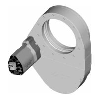
VAT 650 GS Series Installation, Operating, & Maintenance Instructions (77 pages)
Brand:
VAT
| Category:
Control Unit
| Size: 1 MB
Table of Contents
Table of Contents
2
1 Use of Product
4
Technical Data
4
2 Installation
7
Unpacking
7
Installation into the System
7
Tightening Torque
9
Mounting with Centering Rings
9
Mounting with O-Ring in Grooves
10
Admissible Forces
10
Requirements to Sensor Connection
11
Electrical Connection
12
Sensor Supply Concepts
12
Power and Sensor Connection (+24 VDC Sensors)
13
Power and Sensor Connection (±15 VDC Sensors) Without Optional SPS Module
14
Power and Sensor Connection (±15 VDC Sensors) with Optional SPS Module
15
Power Connection for Slave Valve Only
16
RS485 Interface Connection
16
Service Port Connection
16
Valve Cluster Connection
17
3 Operation
20
Introduction
20
Individual Valve Control
21
Individual Valve Status
21
Freeze Mode
21
Position Offset
21
Local Operation
22
Remote Operation
22
Safety Mode
23
Operation under Increased Temperature
23
Behavior During Power up
23
Behavior in Case of Power Failure
23
Display Information
24
Setup Procedure
26
Cluster Address Configuration
26
Interface Configuration
30
Valve and Sensor Configuration
31
Zero
31
Learn
32
Close Valve
33
Open Valve
33
Position Control
33
Pressure Control
34
Operation with 2 Sensors
34
Tuning of Control Performance
35
RS485 Interface
38
Settings
38
Schematics
38
Connection Cable Drawing
41
Digital Inputs
42
Command Syntax
43
Addressed Communication
43
Control Commands
43
Inquiry Commands
45
Setup Commands
51
Error Messages
57
4 Trouble Shooting
58
5 Maintenance & Repairs
60
Maintenance Procedures
61
Option Board
68
Durability of Power Fail Battery
68
Retrofit / Replacement Procedure
69
6 Drawing
72
7 Spare Parts
73
Control Unit
73
Valve Unit
74
Accessories
75
Centering Ring with Viton O-Ring
76
8 Warranty
77
Advertisement
Related Products
VAT 650 GP Series
VAT 650 GQ Series
VAT 650 UL Series
VAT 650 UN Series
VAT 65046 Series
VAT 65048 Series
VAT 650 TJ Series
VAT 650 VJ Series
VAT 650 UK Series
VAT 650 AP Series
VAT Categories
Control Unit
Controller
Refrigerator
Keypad
Control Systems
More VAT Manuals
Login
Sign In
OR
Sign in with Facebook
Sign in with Google
Upload manual
Upload from disk
Upload from URL