Sign In
Upload
Manuals
Brands
Vari Lite Manuals
DJ Equipment
VL3500 Spot Luminaire
Vari Lite VL3500 Spot Luminaire Manuals
Manuals and User Guides for Vari Lite VL3500 Spot Luminaire. We have
3
Vari Lite VL3500 Spot Luminaire manuals available for free PDF download: Service Manual, User Manual
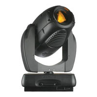
Vari Lite VL3500 Spot Luminaire Service Manual (231 pages)
Spot Luminaire
Brand:
Vari Lite
| Category:
Lighting Equipment
| Size: 9 MB
Table of Contents
Table of Contents
15
Introduction
21
About this Manual
21
Additional Documentation
21
Customer Service
22
Technical Bulletins and Notices
22
Chapter 1. Description
23
Features
24
Standard Features
24
Specific Features
24
Technical Specifications
24
Components
25
External Luminaire Components
25
VL3500 Spot Luminaire Head and Yoke Components
26
Enclosure Components
27
Principles of Operation
28
VL3500 Spot Luminaire
28
Functional Block Diagram
28
Chapter 2. Maintenance
29
Testing
30
Luminaire Self-Tests
30
Calibration Sequence
30
Auto Recalibration
31
Partial Recalibration
31
Sensor Testing
31
Troubleshooting Error Messages
33
Troubleshooting Guide
34
Maintenance Procedures
36
Lamp Replacement
36
Align Lamp
37
Lamp Power Cut-Off Switch
38
Gobo Replacement - Gobo Wheels 1 and 2
39
Color Filter Replacement
41
Ballast Assembly Replacement
42
Color/Dimmer/Strobe Assembly Replacement
43
Main Control Board (MCB) Replacement
44
Ignitor Board Replacement
45
Pan Motor Assembly Replacement
46
Pan Encoder Replacement
47
Pan EOT Sensor Replacement
48
Power Supply (LVS) Replacement
49
Gobo/Shutter Assembly Replacement
50
Spot Optic Assembly Replacement
51
Tilt Motor Assembly Replacement
52
Tilt Encoder Replacement
53
Tilt EOT Sensor Replacement
54
Gobo Timing Adjustments
55
Gobo Gear Planet Alignment
56
Chapter 3. Illustrated Parts Breakdown
57
Drawing Trees
58
VL3500 Spot Luminaire
58
VL3500Q Spot Luminaire
60
Top Assembly
62
Included Items Kit, Spot
62
VL3500 Spot Series Luminaire
64
Generic Luminaire Assembly
67
Generic Luminaire (Quiet) Assembly
69
Head Assembly
71
Head Structure (Standard) Assembly
71
Head Structure (Quiet) Assembly
72
Head Cover Assembly
73
Backcap Assembly
74
80Mm Fan Assembly
76
UV Filter Bulkhead Assembly
77
Gobo/Shutter Assembly
79
Rotating Gobo Wheel Assembly, Shutter
81
Fixed Gobo Wheel Assembly
82
Rotating Gobo Wheel Assembly
83
Roller Pivot Rotate Assembly
84
Shutter Rotate Roller Assembly
85
Long Shaft Motor Assembly
86
Shutter Assembly
87
Shutter Motor Disk Assembly
89
Hot Box Assembly
91
Dual Fan Tray Duct (Standard) Assembly
93
Dual Fan Tray Duct (Quiet) Assembly
94
Head Front Fan (Standard) Assembly
95
Head Front Fan (Quiet) Assembly
96
Transfer Fan Assembly
97
Spot Optic Assembly
99
Zoom Box Assembly
103
Group 4 Lens Assembly
104
Right Edge Bearing Assembly
105
Left Edge Bearing Assembly
106
Zoom Cam Assembly
107
Zoom Motor Tensioning Assembly
108
Interconnect Light Shield Assembly
109
Rod Clamp Assembly
110
Color/Dimmer/Strobe Assembly
111
Motor/Adapter Plate Assembly
114
Fixed Color Wheel Assembly
115
Strobe Assembly
117
Strobe (Quiet) Assembly
118
Right Strobe Blade Assembly
119
Left Strobe Blade Assembly
120
Strobe Motor (Quiet) Assembly
121
Dimmer Wheel Assembly
122
Cyan Wheel Assembly
123
Yellow Wheel Assembly
124
Magenta Wheel Assembly
125
CTO Wheel Assembly
126
Gobo Clamp Assembly
127
Color Clamp Assembly
128
Edge Lead Screw Assembly
129
Yoke Assembly Yoke Assembly
131
Tilt Motor Assembly
133
Relay Electrical Assembly
134
Yoke Fan Assembly
135
Head/Yoke PCB Assemblies Shutter Cable Interconnect Assembly
137
Color Sensor PCB #1 Mount Assembly
138
Color Sensor PCB #2 Mount Assembly
139
Solid State Ignitor PCB
140
Wheel Position Sensor PCB Assembly
141
Color Interconnect Pcb/Cable Assembly
142
Color Interconnect (Quiet) Pcb/Cable Assembly
144
Pan/Tilt Encoder PCB
146
VL3500 Controller PCB Assembly
147
Motor Driver (Piggy Back) PCB
148
Arc Zoom Interconnect PCB Assembly
150
Zoom Sensor (Target) PCB Assembly
152
Index Sensor PCB Assembly
153
Enclosure Assembly Upper Enclosure Assembly
155
Ventilation Cover Assembly - Standard
160
Ventilation Cover Assembly - VL3500 Quiet
161
Panel Assembly
163
DMX Input PCB
164
Display PCB
165
Pan Pulley Assembly
167
Pan Motor Assembly
168
Pan Tube Assembly
169
Cable Assemblies
171
Pan EOT Sensor Electrical Assembly
171
LVS Chassis Ground Cable Assembly
172
Chassis to Yoke Ground Cable Assembly
173
Head to Back Cap Ground Cable Assembly
174
Ignitor to Relay Cable Assembly
175
LVS to Yoke AC Fan Cable Assembly
176
Yoke to AC Fan Cable Assembly
177
Backcap Interlock to Gobo Fan Interlock Cable Assembly
178
Relay to Gobo Fan Interlock Cable Assembly
179
Front Head Fans Cable Assembly
180
Yoke Fan and Relay (Standard) Cable Assembly
181
Air Duct OT Switch Cable Assembly
182
Yoke Fan and Relay (Quiet) Cable Assembly
183
Yoke Fan (Standard) Cable Assembly
184
Yoke Fan (Quiet) Cable Assembly
185
Ignitor to Lamp Socket Cable Assembly
186
Yoke to Head Ground Cable Assembly
187
Head Controller Cable Assembly
188
AC Input Pigtail Cable Assembly
190
EMI Filter to Power Switch Cable Assembly
191
AC Input Splitter Cable Assembly
192
Data I/O Link Cable Assembly
194
Display Cable Assembly
195
Ballast to Controller Cable Assembly
196
DC Output Cable Assembly
197
Pan/Tilt Control Cable Assembly
198
Lamp Supply to Relay Cable Assembly
199
Gobo/Rotate Interconnect Cable Assembly
200
LVS Chassis Ground Cable Assembly
202
Appendix A. Technical Bulletins
203
VL3500 Technical Bulletins
203
Appendix B. Schematic and Wiring Diagrams
205
Solid State Ignitor PCB (Sheet 1 of 1)
205
Gobo Index Sensor PCB (Sheet 1 of 1)
206
DMX Input PCB (Sheet 1 of 1)
207
Gobo Interconnect PCB (Sheet 1 of 1)
208
Color Interconnect PCB (Sheet 1 of 1)
209
Color Sensor #1 PCB (Sheet 1 of 1)
210
Color Sensor #2 PCB (Sheet 1 of 1)
211
Pan/Tilt Encoder PCB (Sheet 1 of 1)
212
VL3500 Controller PCB (Sheet 1 of 10)
213
VL3500 Controller PCB (Sheet 2 of 10)
214
VL3500 Controller PCB (Sheet 3 of 10)
215
VL3500 Controller PCB (Sheet 4 of 10)
216
VL3500 Controller PCB (Sheet 5 of 10)
217
VL3500 Controller PCB (Sheet 6 of 10)
218
VL3500 Controller PCB (Sheet 7 of 10)
219
VL3500 Controller PCB (Sheet 8 of 10)
220
VL3500 Controller PCB (Sheet 9 of 10)
221
VL3500 Controller PCB (Sheet 10 of 10)
222
VL3500 Motor Driver (Piggy Back) PCB (Sheet 1 of 1)
223
Display PCB (Sheet 1 of 1)
224
Zoom Interconnect PCB (Sheet 1 of 1)
225
Zoom Sensor PCB (Sheet 1 of 1)
226
VL3500 Spot Luminaire Wiring Diagram (Sheet 1 of 3)
227
VL3500 Spot Luminaire Wiring Diagram (Sheet 2 of 3)
228
VL3500 Spot Luminaire Wiring Diagram (Sheet 3 of 3)
229
Advertisement
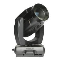
Vari Lite VL3500 Spot Luminaire Service Manual (199 pages)
wash luminaire
Brand:
Vari Lite
| Category:
Lighting Equipment
| Size: 9 MB
Table of Contents
Vl3500 Wash Luminaire
1
Safety Notice
5
Table of Contents
15
Introduction
19
About this Manual
19
Additional Documentation
19
Customer Service
20
Technical Bulletins and Notices
20
Chapter 1. Description
21
Features
22
Standard Features
22
Specific Features
22
Technical Specifications
22
Features Standard Features
22
Components
23
External Luminaire Components
23
Components External Luminaire Components
23
VL3500 Wash Luminaire Head and Yoke Components
24
Enclosure Components
25
Chapter 2. Maintenance
27
Testing
28
Luminaire Self-Tests
28
Calibration Sequence
28
Auto Recalibration
28
Testing Luminaire Self-Tests
28
Partial Recalibration
29
Sensor Testing
29
Warnings and Cautions Exceptional Safety Information for the VL3500 Wash
31
Troubleshooting
32
Error Messages
32
Troubleshooting Error Messages
32
Troubleshooting Guide
33
Maintenance Procedures Lamp Replacement
35
Align Lamp
37
Internal Lens Replacement
38
Internal Lens Replacement (Continued)
39
Front Lens Assembly Removal
40
Front Lens Assembly Removal (Continued)
41
Color Filter Replacement
42
Color Filter Replacement (Continued)
43
Ballast Assembly Replacement
44
Color/Dimmer/Strobe Assembly Replacement
46
Split Lens Assembly Replacement
48
Reflector Replacement
50
Main Control Board (MCB) Replacement
52
Ignitor Board Replacement
53
Pan Motor Assembly Replacement
54
Pan Encoder Replacement
56
Pan EOT Sensor Replacement
58
Power Supply (LVS) Replacement
60
Tilt Motor Assembly Replacement
62
Tilt Encoder Replacement
64
Tilt EOT Sensor Replacement
65
Chapter 3. Illustrated Parts Breakdown
67
Drawing Trees
68
VL3500™ Wash Luminaire
68
Top Assembly
70
VL3500 Wash Included Items Kit
70
VL3500™ Wash Luminaire
72
Vl3500™ Wash Luminaire (Continued)
73
Generic Luminaire Assembly
74
Head Assembly
77
Head Structure Assembly
77
Front Stippled Lens Assembly
78
Front Clear Lens Assembly
79
Front Fresnel Lens Assembly
80
Head Cover Assembly
81
Backend Assembly
82
80Mm Fan Assembly
84
Dual Fan Duct Assembly
85
Reflector Mount Assembly
86
Hot Box Assembly
87
Dual Fan Tray Assembly
89
Head Front Fan Assembly
90
Internal Lens Assembly
91
Internal Lens Rail Assembly
93
Internal Lens Splitter Assembly
95
Actuator Assembly
97
Fresnel Internal Lenses
98
Internal Lens Mounting Kit
99
Color/Effect/Strobe Module
100
Fixed Color Wheel Assemblies
103
Strobe System Assembly
105
Rear Strobe Blade Assembly
107
Front Strobe Blade Assembly
108
Yoke Assembly Yoke Assembly
109
Tilt Motor Assembly
111
Relay Electrical Assembly
112
Yoke Fan Assembly
113
Head/Yoke PCB Assemblies
115
Head Cable Interconnect
115
Color Sensor PCB Offset Assembly
116
Color Sensor PCB Inline Assembly
117
Solid State Ignitor PCB
118
Wheel Position Sensor PCB Assembly
119
Pan/Tilt Encoder PCB
120
VL3500 Wash Controller PCB Assembly
121
Enclosure Assembly Upper Enclosure Assembly
123
Ventilation Cover Assembly
129
Exhaust Fan Assembly
131
Panel Assembly
132
DMX Input PCB
133
Display PCB
134
Pan Pulley Assembly
135
Pan Motor Assembly
136
Pan Tube Assembly
138
1500W Arc Ballast Module Assembly
139
Cable Assemblies
141
Pan EOT Sensor Electrical Assembly
141
LVS Chassis Ground Cable Assembly
142
Chassis to Yoke Ground Cable Assembly
143
Ignitor to Relay Cable Assembly
144
LVS to Yoke Dual AC Fan Cable Assembly
145
Yoke to Dual AC Fan Cable Assembly
146
OT Switch 1 to OT Switch 2 Cable Assembly
147
Backcap Interlok to OT Switch 1 Cable Assembly
148
OT Switch to Ground Cable Assembly
149
Tilt Harness Cable Assembly
150
Internal Lens Interconnect Cable Assembly
151
Color Harness Cable Assembly
152
Internal-Lens Split Motor Cable Assembly
153
Zoom Motor Cable
154
Transfer Fans Cable Assembly
155
Upper Enclosure Fans Cable Assembly
156
Yoke Fan and Relay Cable Assembly
157
Yoke Fan Cable Assembly
158
OT Switch to Interlok Cable Assembly
159
OT Switch 1 to OT Switch 2 Cable Assembly
160
Ignitor to Lamp Socket Cable Assembly
161
Chassis to Yoke Ground Cable Assembly
162
Zoom Motor Cable Assembly
163
AC Input Pigtail Cable Assembly
164
EMI Filter to Power Switch Cable Assembly
165
AC Input Splitter Cable Assembly
166
Data I/O Link Cable Assembly
168
Display Cable Assembly
169
Ballast to Controller Cable Assembly
170
DC Output Cable Assembly
171
Pan/Tilt Control Cable Assembly
172
Lamp Supply to Relay Cable Assembly
173
VL3500™ Wash Luminaire Technical Bulletins
175
Schematics and Diagrams List
177
VL3500 Wash Wiring Diagram (Sheet 1 of 3)
179
VL3500 Wash Wiring Diagram (Sheet 2 of 3)
180
VL3500 Wash Wiring Diagram (Sheet 3 of 3)
181
Solid State Ignitor PCB (Sheet 1 of 1)
182
DMX Input PCB (Sheet 1 of 1)
183
Color Sensor Offset PCB (Sheet 1 of 1)
184
Color Sensor Inline PCB (Sheet 1 of 1)
185
Pan/Tilt Encoder PCB (Sheet 1 of 1)
186
VL3500 Controller PCB (Sheet 1 of 10)
187
VL3500 Controller PCB (Sheet 2 of 10)
188
VL3500 Controller PCB (Sheet 3 of 10)
189
VL3500 Controller PCB (Sheet 4 of 10)
190
VL3500 Controller PCB (Sheet 5 of 10)
191
VL3500 Controller PCB (Sheet 6 of 10)
192
VL3500 Controller PCB (Sheet 7 of 10)
193
VL3500 Controller PCB (Sheet 8 of 10)
194
VL3500 Controller PCB (Sheet 9 of 10)
195
VL3500 Controller PCB (Sheet 10 of 10)
196
Display PCB (Sheet 1 of 1)
197
Appendix A. Technical Bulletins
175
Appendix B. Schematics and Wiring Diagrams
177
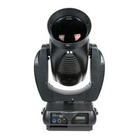
Vari Lite VL3500 Spot Luminaire User Manual (88 pages)
Brand:
Vari Lite
| Category:
DJ Equipment
| Size: 3 MB
Table of Contents
Table of Contents
15
About this Manual
19
Additional Documentation
19
Text Conventions
20
Customer Service
20
Chapter 1. Description
21
Features
22
Standard Features
22
Specific Features
22
Features Standard Features
22
Components
23
Included Items
23
Replacement Items/Accessories
23
Components Included Items
23
Luminaire Overview
24
Chapter 2. Installation
25
Power and Data Cabling Requirements
26
Power
26
Data Cables
27
Recommended Cable Types/Manufacturers
28
Male Termination Connector
28
Warnings and Cautions
29
Exceptional Safety Information for the VL3500 Wash
29
Installation Procedures
30
Hanging the Luminaire
30
Floor Mounting the Luminaire
33
Connecting Data and Power
33
Powering up
34
Power up and Configuration Procedure
34
Addressing
35
Program Starting Address
35
Program Starting Address Without Calibrating Luminaire
35
Addressing Program Starting Address
35
Powering down and Packing up
36
Pack-Up Cues for Shipping VL3500™ Wash Luminaires
36
Packing for Transportation and Shipment
36
Channel Mapping
38
Control Channel Functions
39
Color Control
41
Color Mixing
41
Fixed Color Wheel 1
41
DMX Mapping Color Control
41
Fixed Color Wheel 2
42
Beam Control
44
Strobe
44
Aperture
44
Luminaire Timing
45
Timing Channel Information
45
Updating Software
54
Reprogramming Luminaires
54
Serial-Port Download
54
Reprogramming Procedure
55
USB Download
57
Kit Components
57
Transferring Software from Luminaire to Luminaire
57
Chapter 4. Menu System
59
Chapter 3 Menu Operation
60
What Is the Menu System
60
Controls Operation
60
Default State
61
Shortcuts
61
Menu Functions
62
Menu System Overview
62
Menu System Function Chart
63
Menu Function Definitions
66
Self-Tests
69
Running Parameter Tests
69
Appendix A. Troubleshooting and Maintenance
71
Troubleshooting
72
Error Messages
72
Troubleshooting Error Messages
72
Troubleshooting Guide
73
Routine Maintenance
74
Lamp Replacement
74
Align Lamp
75
Internal Lens Replacement
76
Internal Lens Replacement (Continued)
77
Front Lens Assembly Removal
78
Front Lens Assembly Removal (Continued)
79
Color Filter Replacement
80
Color Filter Replacement (Continued)
81
Cleaning Front Lens
82
Appendix B. Technical Specifications
83
VL3500™ Wash Luminaire
83
Photometric Data
85
Advertisement
Advertisement
Related Products
Vari Lite VL3500 SERIES
Vari Lite VL3015
Vari Lite VL3515
Vari Lite VL2416
Vari Lite VL6000 Beam Luminaire
Vari Lite VL2202
Vari-Lite VL10 BeamWash
Vari-Lite VL 2600
Vari-Lite BeamLine VL800
Vari-Lite VL5LED WASH
Vari Lite Categories
DJ Equipment
Lighting Equipment
Light Fixture
Lantern
Flood Light
More Vari Lite Manuals
Login
Sign In
OR
Sign in with Facebook
Sign in with Google
Upload manual
Upload from disk
Upload from URL