
Subscribe to Our Youtube Channel
Related Manuals for Valleylab Force EZ - C Series

Summary of Contents for Valleylab Force EZ - C Series
- Page 1 Service Manual Valleylab Force EZ™-C Series Electrosurgical Generator with Instant Response™ Technology...
- Page 2 This manual and the equipment it describes are for use only by qualified medical professionals trained in the particular technique and surgical procedure to be performed. It is intended as a guide for servicing the Valleylab Force EZ™-C Series Electrosurgical Generator only.
-
Page 3: Conventions Used In This Guide
Conventions Used in this Guide Warning Indicates a potentially hazardous situation which, if not avoided, could result in death or serious injury. Caution Indicates a hazardous situation which, if not avoided, may result in minor or moderate injury. Important Indicates an operating tip or Notice maintenance suggestion. -
Page 4: Warranty
This warranty does not apply to any product, or part thereof, which has been repaired or altered outside Valleylab’s factory in a way so as, in Valleylab’s judgment, to affect its stability or reliability, or which has been subjected to misuse, neglect, or accident. - Page 5 District Court of the County of Boulder, State of Colorado, USA. Valleylab, its dealers, and representatives reserve the right to make changes in equipment built and/or sold by them at any time without incurring any obligation to make the same or similar changes on equipment previously built and/or sold by them.
- Page 6 Force EZ-C Series Service Manual...
-
Page 7: Table Of Contents
Table of Contents Preface................Conventions Used in this Guide. - Page 8 Dimensions and Weight............Operating Parameters .
- Page 9 Instant Response Algorithm ........... . 5-11 Display Board.
- Page 10 Checking High Frequency Leakage Current and Ground Resistance..... 6-21 Calibrating the Force EZ-C Series Electrosurgical Generator ......6-22 Preparing for Calibration .
- Page 11 Front Panel Footswitch Receptacle ..........8-10 Front Panel Knob .
- Page 12 Returning Circuit Boards ............Service Centers .
-
Page 13: List Of Figures
List of Figures Figure 3-1. The front panel Figure 3-2. The front panel - continued Figure 3-3. Controls and receptacles on the rear panel Figure 3-4. The option panel on the generator rear panel with the plate removed to show the serial and RF activation ports Figure 4-1. - Page 14 Figure 8-3. Left front heat sink components 8-18 Figure 8-4. Left rear heat sink components 8-20 Figure 8-5. Right heat sink components 8-22 Figure 8-6. Connections to the low voltage power supply 8-25 Figure 8-7. Cable connections to the power entry module 8-27 Figure 10-1.
-
Page 15: Section 1. Service Personnel Safety
S E C T I O N Service Personnel Safety Valleylab stresses safety in the use and servicing of its electrosurgical equipment. This section presents the following: • Safety information • Warnings, Cautions, and Notices Refer to the Preface, Conventions, for further information on Warnings, Cautions, and Notices. -
Page 16: Safety Information
Safety Information Safety Information The safe and effective servicing of electrosurgical equipment depends to a large degree on factors solely under the control of the service person. There is no substitute for a properly trained and vigilant service staff. Warnings, Cautions, and Notices Before servicing the generator, it is important that you read, understand, and follow the instructions supplied with it and with any other equipment used to install, test, adjust, or repair the generator. -
Page 17: Fire/Explosion Hazards
Patient Return Electrodes Warning Using a patient return electrode without the REM safety feature will not activate the Valleylab REM Contact Quality Monitoring System. Fire/Explosion Hazards Warning Danger: Explosion Hazard –þDo not install the generator in the presence of flammable anesthetics, gases, liquids, or objects. -
Page 18: Electric Shock Hazards
Warnings, Cautions, and Notices Electric Shock Hazards Warning Connect the generator power cord to a properly grounded receptacle. Do not use power plug adapters. Do not connect a wet power cord to the generator or to the wall receptacle. To allow stored energy to dissipate after power is disconnected, wait at least five minutes before replacing parts. -
Page 19: Calibration
Warnings, Cautions, and Notices Calibration Caution To avoid inadvertent coupling and/or shunting of RF currents around the resistor elements, keep the resistors at least 10.2 cm (4 in.) away from any metal surface including tabletops and other resistors. This is especially true if several resistors are connected in series or parallel to obtain a specified value. - Page 20 Force EZ-C Service Manual...
-
Page 21: Section 2. Introduction
S E C T I O N Introduction This manual provides instructions for servicing the Valleylab Force EZ-C Series Electrosurgical Generator. This section introduces the features and components of the generator. Additional information about using the generator is available in the Force EZ-C Series Electrosurgical Generator with Instant Response Technology User’s Guide. -
Page 22: General Description
General Description General Description The Valleylab Force EZ-C Series Electrosurgical Generator is an isolated output electrosurgical generator that provides the power for cutting, desiccating, and fulgurating tissue during electrosurgery. The generator is specifically designed for use in bipolar or monopolar electrosurgery. -
Page 23: Instant Response Technology
Instant Response Technology Instant Response Technology The Force EZ-C Series Electrosurgical Generator automatically senses resistance and adjusts the current and output voltage to maintain a consistent effect across different tissue density. This adjustment is based on the selected mode, the power setting, and the level of tissue resistance. -
Page 24: Coag Modes
The Force EZ-C Series Electrosurgical Generator uses the Valleylab REM Contact Quality Monitoring System to monitor the quality of electrical contact between the patient return electrode and the patient. -
Page 25: How The Rem System Works
Warning Using a patient return electrode without the REM safety feature will not activate the Valleylab REM Contact Quality Monitoring System. When you use a patient return electrode that does not have the REM safety feature, the REM system does not monitor the patient contact area as previously described. -
Page 26: High (Fulgurate) Coag Settings
Special Features High (Fulgurate) Coag Settings The high (fulgurate) coag mode provides two settings: • High 1 produces coagulation of smaller areas without touching the electrode tip to the tissue. • High 2 produces coagulation of larger areas without touching the electrode to the tissue. -
Page 27: Section 3. Controls, Indicators, And Receptacles
S E C T I O N Controls, Indicators, and Receptacles This section describes the front and rear panels, including all controls, indicators, and receptacles. Force EZ-C Series Service Manual... -
Page 28: Front Panel
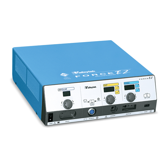
Front Panel Front Panel Figure 3-1. Bipolar Indicator The front panel When you activate the generator in bipolar mode, this bar illuminates blue and an activation tone sounds. Bipolar Display Shows the power setting, in watts, for bipolar output. Bipolar Power Control Knob To increase (+) the power, turn the knob clockwise. - Page 29 Front Panel Coag Indicator When you activate the generator in coag mode, this bar illuminates blue and an activation tone sounds. Coag Display Shows the power setting, in watts, for coag output. Coag Power Control Knob To increase (+) the power, turn the knob clockwise. To decrease (–) the power, turn the knob counterclockwise.
- Page 30 Front Panel Figure 3-2. Patient Return Electrode Receptacle The front panel - continued For monopolar electrosurgery, connect a patient return electrode to this receptacle. Monopolar Instrument Receptacle You can connect either a handswitching instrument (three-pin connector) or a footswitching instrument (single-pin connector) to this receptacle. To activate a footswitching instrument, connect a monopolar footswitch to the rear panel.
- Page 31 Connect a two-pedal Valleylab monopolar footswitch to this receptacle. Press the Footswitch Selector button to select bipolar or accessory output. Use only a Valleylab monopolar footswitch with the Force EZ-C Series Electrosurgical Generator. Use on an incompatible footswitch may cause unexpected output.
-
Page 32: Rear Panel
Rear Panel Rear Panel Figure 3-3. Volume Control Controls and receptacles on the The Force EZ-C Series Electrosurgical Generator includes an audible tone rear panel that sounds in two circumstances: • When you activate the generator • When any alarm occurs You can adjust the volume of the activation tones. - Page 33 The footswitch will not activate instruments connected to the Monopolar Instrument or Accessory Instrument receptacles on the front panel. Monopolar Footswitch Receptacle Connect a two-pedal Valleylab monopolar footswitch to this receptacle if you connect an instrument to the Monopolar Instrument receptacle on the front panel.
-
Page 34: Option Panel
Option Panel Option Panel A removable plate on the rear panel covers a serial port and a radio frequency (RF) activation port. To review the technical specifications for each port, refer to Section 4, Technical Specifications. Serial Port Allows connection of a computer to the generator. You can obtain information about the generator using the RS-232 communications protocol. -
Page 35: Section 4. Technical Specifications
S E C T I O N Technical Specifications All specifications are nominal and subject to change without notice. A specification referred to as “typical” is within ± 20% of a stated value at room temperature (77° F/25° C) and a nominal input power voltage. -
Page 36: Performance Characteristics
Cooling natural convection; side and rear panel vents Display eight digital seven-segment displays: 1.9 cm (0.75 in.) each Mounting Valleylab Universal Cart (UC8009), Force Argon Unit, or any stable flat surface Dimensions and Weight Width 40.6 cm (16 in.) Depth 39.5 cm (15.6 in.) -
Page 37: Transport And Storage
Performance Characteristics Transport and Storage Ambient temperature -34° to 65° C (-29° to 149° F) range Relative humidity 25% to 85%, noncondensing Atmospheric pressure 500 to 1060 millibars Duration of storage If you stored the generator longer than one year, replace the battery for battery-backed RAM and complete a full test and recalibration before use. -
Page 38: Audio Volume
Performance Characteristics Audio Volume The audio levels stated below are for activation tones (bipolar, cut, and coag) and alarm tones (REM and system alarms) at a distance of one meter. Alarm tones meet the requirements for IEC 60601-2-2 and AAMI HF18. Activation Tone 45 to ≥... -
Page 39: Serial Port
Performance Characteristics REM Alarm Activation REM patient return electrode: When the measured resistance exceeds the standard range of safe resistance (below 5 ohms or above 135 ohms) or when the initial measured contact resistance increases by 40% (whichever is less), the REM Alarm indicator flashes red, a tone sounds twice, and the generator disables RF output. -
Page 40: Input Power
Performance Characteristics Input Power 100–120 Volt 220–240 Volt Maximum VA input: Maximum VA input: Idle: 50 VA Idle: 50 VA Bipolar: 500 VA Bipolar: 500 VA Cut: 850 VA Cut: 850 VA Coag: 500 VA Coag: 500 VA Full regulation range: 90–135 Vac Full regulation range: 186–264 Vac Operating range: 85–140 Vac Operating range: 170–280 Vac... -
Page 41: Low Frequency (50-60 Hz) Leakage Current
Performance Characteristics Low Frequency (50-60 Hz) Leakage Current Enclosure source < 100 µA current, ground open Source current, patient Normal polarity, intact ground: < 10 µA leads, all outputs Normal polarity, ground open: < 50 µA Reverse polarity, ground open: < 50 µA Sink current at high <... -
Page 42: Standards And Iec Classifications
Standards and IEC Classifications Standards and IEC Classifications The Force EZ-C Series Electrosurgical Generator meets all pertinent clauses of the IEC 60601-1 second edition and IEC 60602-2-2 third edition. ATTENTION Consult accompanying documents. The generator output is floating (isolated) with respect to ground. -
Page 43: Liquid Spillage (Iec 60601-2-2 Clause 44.3)
Standards and IEC Classifications Liquid Spillage (IEC 60601-2-2 Clause 44.3) The Force EZ-C Series Electrosurgical Generator enclosure is constructed so that liquid spillage in normal use does not wet electrical insulation or other components which, when wetted, are likely to adversely affect the safety of the equipment. - Page 44 Standards and IEC Classifications Guidance and manufacturer's declaration - electromagnetic emissions The Force EZ-C Series Electrosurgical Generator is intended for use in the electromagnetic environment specified below. The customer or the user of the Force EZ-C Series Electrosurgical Generator should ensure that it is used in such an environment.
- Page 45 Standards and IEC Classifications Guidance and manufacturer's declaration - electromagnetic immunity The Force EZ-C Series Electrosurgical Generator is intended for use in the electromagnetic environment specified below. The customer or the user of the Force EZ-C Series Electrosurgical Generator should assure that it is used in such an environment.
- Page 46 Standards and IEC Classifications Guidance and manufacturer's declaration - electromagnetic immunity The Force EZ-C Series Electrosurgical Generator is intended for use in the electromagnetic environment specified below. The customer or the user of the Force EZ-C Series Electrosurgical Generator should assure that it is used in such an environment.
- Page 47 Standards and IEC Classifications Recommended separation distances between portable and mobile RF communication equipment and the Force EZ-C Series Electrosurgical Generator The Force EZ-C Series Electrosurgical Generator is intended for use in an electromagnetic environment in which radiated RF disturbances are controlled. The Customer or the user of the Force EZ-C Series Electrosurgical Generator can help prevent electromagnetic interferences by maintaining a minimum distance between portable and mobile RF communications equipment (transmitters) and the Force EZ-C Series Electrosurgical Generator as recommended below, according to the maximum output power of the communications equipment.
-
Page 48: Output Characteristics
Output Characteristics Output Characteristics Available Power Settings in Watts Bipolar Monopolar Cut: Pure Monopolar Cut: Blend 4-14 Force EZ-C Series Service Manual... -
Page 49: Maximum Output For Force Ez-C Series Electrosurgical Generator Modes
Output Characteristics Monopolar Coag Maximum Output for Force EZ-C Series Electrosurgical Generator Modes Power readouts agree with actual power into rated load to within 15% or 5 watts, whichever is greater. Crest Factor Open Circuit P- (typical @ Mode P Voltage (max) Rated Load Power (max) Rated Load) -
Page 50: Output Waveforms
Output Characteristics Output Waveforms Instant Response Technology, an automatic adjustment, applies to the bipolar mode, the cut modes, and the low 2 and low 3 coag settings. It does not apply to the low 1, high 1, and high 2 coag settings. As tissue resistance increases, the generator produces constant current followed by constant power followed by constant voltage. -
Page 51: Output Power Vs. Resistance Graphs
Output Power vs. Resistance Graphs Output Power vs. Resistance Graphs The graphs that follow depict the changes for each mode at specific power settings. Bipolar Graph The insulating surface described in IEC 60601-2-2 and full length leads was used to obtain the bipolar output measurements. Figure 4-1. - Page 52 Output Power vs. Resistance Graphs Monopolar Cut Graphs Valleylab used the procedures described in IEC 60601-2-2 and full length leads to obtain the monopolar cut output measurements. Figure 4-2. Pure mode — load resistance vs. output power 300 W 120 W...
- Page 53 Output Power vs. Resistance Graphs Monopolar Coag Graphs The procedures described in IEC 60601-2-2 and full length leads were used to obtain the monopolar coag output measurements. Figure 4-4. Low 1 (Desiccate) mode — load resistance vs. output power Load Resistance (ohms) Figure 4-5.
- Page 54 Output Power vs. Resistance Graphs Figure 4-6. Low 3 (Desiccate) mode — load resistance vs. output power 120 W 60 W 800 1000 1200 1400 1600 1800 2000 Load Resistance (ohms) Figure 4-7. High 1 (Fulgurate) mode — load resistance vs. output power 120 W 60 W 800 1000 1200 1400 1600 1800 2000...
- Page 55 Output Power vs. Resistance Graphs Figure 4-8. High 2 (Fulgurate) mode — load resistance vs. output power Load Resistance Force EZ-C Series Service Manual 4-21...
-
Page 56: Figure 4-9. Standard Bipolar Mode @ 100 Ohms - Generator Setting Vs. Output Power
Output Power vs. Resistance Graphs Output Power vs. Generator Settings Figure 4-9. Standard Bipolar mode @ 100 ohms — generator setting vs. output power Generator Setting Figure 4-10. Standard Bipolar mode — peak voltage vs. output power Output Power (watts) 4-22 Force EZ-C Series Service Manual... -
Page 57: Figure 4-11. Pure Mode @ 300 Ohms - Generator Setting Vs. Output Power
Output Power vs. Resistance Graphs Figure 4-11. Pure mode @ 300 ohms — generator setting vs. output power Generator Setting Figure 4-12. 1000 Pure mode — peak voltage vs. output power Output Power (watts) Force EZ-C Series Service Manual 4-23... -
Page 58: Figure 4-13. Blend Mode @ 300 Ohms - Generator Setting Vs. Output Power
Output Power vs. Resistance Graphs Figure 4-13. Blend mode @ 300 ohms — generator setting vs. output power Generator Setting Figure 4-14. 1600 Blend mode — peak voltage vs. output power 1400 1200 1000 Output Power (watts) 4-24 Force EZ-C Series Service Manual... -
Page 59: Figure 4-15. Low 1 (Desiccate) Mode @ 500 Ohms - Generator Setting Vs. Output Power
Output Power vs. Resistance Graphs Figure 4-15. Low 1 (Desiccate) mode @ 500 ohms — generator setting vs. output power Generator Setting Figure 4-16. Low 1 (Desiccate) mode — peak 2500 voltage vs. output power 2000 1500 1000 90 100 110 120 Output Power (watts) Force EZ-C Series Service Manual 4-25... -
Page 60: Figure 4-17.Low 2 (Desiccate) Mode @ 300 Ohms- Generator Setting Vs. Output Power
Output Power vs. Resistance Graphs Figure 4-17.Low 2 (Desiccate) mode @ 300 ohms— generator setting vs. output power Generator Setting Figure 4-18. Low 2 (Desiccate) mode — peak voltage vs. output power 100 110 120 Output Power (watts) 4-26 Force EZ-C Series Service Manual... -
Page 61: Figure 4-19. Low 3 (Desiccate) Mode @ 300 Ohms- Generator Setting Vs. Output Power
Output Power vs. Resistance Graphs Figure 4-19. Low 3 (Desiccate) mode @ 300 ohms— generator setting vs. output power Generator Setting Figure 4-20. Low 3 (Desiccate) mode — peak voltage vs. output power 100 110 120 Output Power (watts) Force EZ-C Series Service Manual 4-27... -
Page 62: Figure 4-21. High 1 (Fulgurate) Mode @ 500 Ohms- Generator Setting Vs. Output Power
Output Power vs. Resistance Graphs Figure 4-21. High 1 (Fulgurate) mode @ 500 ohms— generator setting vs. output power Generator Setting Figure 4-22. High 1 (Fulgurate) mode — peak 3500 voltage vs. output power 3000 2500 2000 1500 1000 100 110 120 Output Power (watts) 4-28 Force EZ-C Series Service Manual... -
Page 63: Figure 4-23. High 2 (Fulgurate) Mode @ 500 Ohms- Generator Setting Vs. Output Power
Output Power vs. Resistance Graphs Figure 4-23. High 2 (Fulgurate) mode @ 500 ohms— generator setting vs. output power Generator Setting Figure 4-24. High 2 (Fulgurate) mode — peak 4500 voltage vs. output power 4000 3500 3000 2500 2000 1500 1000 90 100 110 120 Output Power (watts) - Page 64 4-30 Force EZ-C Series Service Manual...
-
Page 65: Section 5. Principles Of Operation
S E C T I O N Principles of Operation This section provides detailed information about how the Force EZ-C Electrosurgical Generator functions and how the internal components of the generator interact. The Force EZ-C Series Electrosurgical Generator circuitry resides on four printed circuit boards: the Control board, the Display board, the Footswitch board, and the power supply/radio frequency (RF) board. -
Page 66: Figure 5-1. A Block Diagram Of The Force Ez-C Series Generator
Figure 5-1. A block diagram of the Force EZ-C Series generator Force EZ-C Series Service Manual... -
Page 67: Functional Overview
Instant Response Algorithm in this section. REM Contact Quality Monitoring System The Force EZ-C Series Electrosurgical Generator uses the Valleylab REM Contact Quality Monitoring System to monitor the quality of electrical contact between the patient return electrode and the patient. The REM system reduces the risk of burns at the return electrode site during monopolar electrosurgery. -
Page 68: Control Board
Control Board REM Alarm Activation The REM Alarm indicator flashes red, a tone sounds, and the generator stops producing output power when either of the following occurs: • The measured resistance is below 5 ohms or above 135 ohms, the limits of the standard range of safe resistance. -
Page 69: Microcontrollers
Control Board Microcontrollers Two microcontrollers on the Control board (the main microcontroller and the feedback microcontroller) work together to control the generator. They communicate with each other through a shared RAM. The main microcontroller (U5) performs all system functions, except the time-critical real time feedback control of generator RF output. -
Page 70: Feedback Microcontroller
Control Board Main Microcontroller Memory An ST microelectronics PSD835G2 programmable systems device (U3) provides program memory (512K x 8 external flash memory) and data memory (2K x 8 external battery-backed static RAM) for the main microcontroller. Additional data memory is available from these sources: •... -
Page 71: Shared Ram
Control Board Shared RAM An IDT 713425A device (U4) with semaphore flags provides the 4K x 8 external shared static RAM. The shared RAM allows the main microcontroller (U5) and the feedback microcontroller (U11) to share common variables. It functions as a communications interface between the main and feedback microcontrollers. -
Page 72: Power Supply Supervisor Circuit
Control Board Power Supply Supervisor Circuit The power supply supervisor circuit (U14), a MAX691, generates a Reset signal and a Reset\ signal for the main microcontroller (U5) if the power supply voltage to the Control board drops below 4.65 V. Reset\ also places the PSD835G2 (U3) and the PSD835G2 (U6) in sleep mode and disables the 2K x 8 external static RAM. -
Page 73: T_On Average Check
Control Board If the code received by the T_ON ASIC is not valid, the internal program sets an error flag, deactivates all output signals, and remains in an error state until the system is reset. T_ON Average Check Hardware integrates the T_ON waveform generator output waveform and returns it to the main microcontroller as an analog value called T_ON average. -
Page 74: Dosage Error Algorithm
Control Board Dosage Error Algorithm The basis for the dosage error algorithm for the closed loop modes (bipolar, cut, and the low 2 and low 3 settings) is a comparison between two microcontroller/ sensor sets: • backup current and voltage sensors, read by the main microcontroller (U5) •... -
Page 75: Instant Response Algorithm
Control Board Instant Response Algorithm The Force EZ-C Series Electrosurgical Generator’s Instant Response system is a closed loop control algorithm implemented in microcontroller firmware. The system applies it to some settings, but not others: • Applied to • bipolar • monopolar cut modes •... -
Page 76: Display Board
Display Board Analog to Digital Saturation If the analog to digital converter is saturated, the Instant Response feedback loop reduces the output voltage to allow an unsaturated operating condition. The feedback loop switches the control function to maintain the analog to digital converter in the linear operating range. -
Page 77: Rf Indicator Lamps
Display Board RF Indicator Lamps The RF indicator lamps illuminate during RF activation to indicate the presence of RF power. Four incandescent bulbs (LP1–LP12) illuminate each of the three indicator bars (bipolar, cut, and coag) on the front panel: • LP1–LP4 illuminate the bipolar bar, changing its color from white to blue to indicate bipolar activation. -
Page 78: Mode Selection Switches
Display Board U5 drives the seven-segment displays that indicate power settings: • DS1 and DS2 indicate the bipolar power setting • DS3–DS5 indicate the cut power setting • DS6–DS8 indicate the coag power setting. The anodes of these displays each connect to only one digit line of the driver. The effective duty cycle is 1/8 for each seven-segment display. -
Page 79: Rem Switch Circuit
Display Board REM Switch Circuit The REM switch circuit detects the presence of a REM patient return electrode plugged into the Patient Return Electrode receptacle. The center plastic pin on the REM plug moves a mechanical lever in the receptacle, allowing it to sense the plug and open S9. -
Page 80: Footswitch Board
The monopolar footswitch connector (J1) provides footswitching capability for the multipin Monopolar Instrument receptacle located on the front panel. Use only a Valleylab footswitch with the Force EZ-C Series Electrosurgical Generator. Use of an incompatible footswitch may cause unexpected output. The bipolar footswitch connector (J4) provides footswitching capability for the Bipolar Instrument receptacle located on the front panel. -
Page 81: Power Supply/Rf Board Interfaces
Power Supply/RF Board Power Supply/RF Board Interfaces The Power Supply/RF board interfaces to other boards and generator components: • Control board • Footswitch board • heat sink components (RF damping resistors and the RF MOSFET) • a series of single wire attachment points for connecting the sense transformers •... - Page 82 Power Supply/RF Board Auto Mains Switching Circuitry The auto mains switching circuit detects the AC line voltage level and controls the triac (D3). This triac controls the topology of the AC/DC converter. For 110 to 120 Vac operation, the triac is on, which connects the AC neutral to the center of the AC/DC converter capacitor bank (C58–C61).
- Page 83 Power Supply/RF Board Important T1 consists of two Transformer T1 transformer-couples the gate driver circuitry for each MOSFET transformers electrically and to provide AC line isolation. It consists of a dual MOSFET driver (U1) and magnetically isolated from various damping resistors. Resistors R40, R58, R63, and R78 minimize turn-off each other but assembled into oscillations.
-
Page 84: Low Voltage Power Supply
Power Supply/RF Board Low Voltage Power Supply The low voltage power supply, rated for 40 watts, delivers a regulated +5 Vdc and ±12 Vdc output. This power supply has a universal input and works for both input voltage ranges. It has internal current limiting, overvoltage, and thermal shutdown protection. -
Page 85: Rf Output Stage
Power Supply/RF Board RF Output Stage Warning High frequency, high voltage signals that can cause severe burns are present in the RF output stage and in the associated mounting and heat sink hardware described in this manual. Take appropriate precautions when testing and troubleshooting this area of the generator. - Page 86 Power Supply/RF Board The current sense circuit, which uses current transformers T5 and T6, works the same as the voltage sense circuit. T6 senses bipolar current and T5 senses monopolar current. Relay K9 selects the appropriate current. Note that the current scaling relays (K5–K7) switch at different power settings than the voltage scaling relays.
- Page 87 Power Supply/RF Board Cut Modes In the cut modes, the K1 setting allows the following conditions: • diode CR7 is in parallel with the MOSFET body drain diode • C62 and C65 are across the MOSFET • the transformer primary consists of windings 1-2 and 3-4 in series K15 is closed so the series capacitor bank (C143, C154, C159, C165, and C166) is across the output.
-
Page 88: Spark Control Circuit
Power Supply/RF Board The high 2 (fulgurate) setting works the same as the high 1 (fulgurate) setting, except the T_ON\signal is a continuous pulse train with a pulse width of 1.69 µs and a frequency of 30 kHz. In the low 1 coag setting, the K1 setting allows these conditions: •... -
Page 89: Rf Leakage Sensing And Reduction Circuit
Power Supply/RF Board RF Leakage Sensing and Reduction Circuit For the high (fulgurate) settings, the pulse repetition period for high voltage RF output varies with changes in spark and patient tissue impedance to limit the RF leakage current to a desired level. The divider (R90, R94) located on the primary side of T4 produces the VSENSE signal. -
Page 90: Audio Circuit
Power Supply/RF Board Oscillator The oscillator circuit consists of a 74HCT4060 oscillator/divider (U30) using a 5 MHz ceramic resonator as the frequency determining element. The output of the oscillator connects internally to the input of a counter/divider chain. The Q6 output of the divider yields a 78.13 kHz square wave, applying it to the input of two 4081 AND gates (U27A and U34A) for buffering and gating with the ISO_TST\ signal. - Page 91 Power Supply/RF Board Enabling either UP_TONE\ or RF_TONE\ low pulls the voltage at the noninverting input of U5B below the Vref threshold present at U5B’s inverting input. This condition turns the output transistor of U5B (open collector) on, grounding R31 and allowing U6A to oscillate. Vref, used throughout the audio circuit, results from dividing the +12 V power supply down to about 2 volts through R50 and R54 while C33 provides low pass filtering for Vref.
-
Page 92: Footswitch Decode Circuit
Power Supply/RF Board Footswitch Decode Circuit The Footswitch board resides inside the rear panel of the Force EZ-C Series Electrosurgical Generator. The 3-pin Bipolar Footswitch receptacle (J4) and the 4-pin Monopolar Footswitch receptacle (J1), mounted on the board, extend through the rear panel. The footswitch decode circuit resides on the Power Supply/RF board. -
Page 93: Section 6. Setup, Tests, And Adjustments
S E C T I O N Setup, Tests, and Adjustments After unpacking or after servicing the Valleylab Force EZ-C Series Electrosurgical Generator, set it up and verify that it functions correctly. If the generator does not satisfactorily complete the self-test, calibrate the generator to ensure its accuracy. -
Page 94: Setting Up The Generator
Verify the generator is off by pressing the power switch off ( O ). Place the generator on any stable flat surface, such as a table, platform, or Valleylab cart. Valleylab recommends carts with conductive wheels. For details, refer to the procedures for your institution or to local codes. - Page 95 Setting Up the Generator Turn on the generator by pressing the power switch on ( | ). Verify the following: • All visual indicators and displays on the front panel illuminate. • Activation tones sound to verify that the speaker is working properly. Important Status for the last used mode If the self-test is successful, a tone sounds.
-
Page 96: Connections For Bipolar Surgery
Figure 6-2. Bipolar connections (footswitch activation from the Footswitch receptacle on the front panel) handswitching or footswitching instrument Valleylab monopolar Press the Footswitch Selector button until the left arrow indicator illuminates green. Force EZ-C Series Service Manual... -
Page 97: Setting The Bipolar Output
Connections for Monopolar Surgery If you plan to use a footswitching monopolar instrument, you must connect a Valleylab monopolar footswitch. You may also use a footswitch to activate a handswitching instrument. For most procedures, you will connect only one monopolar instrument (handswitching or footswitching). - Page 98 Figure 6-4. Monopolar connections (handswitching instrument) handswitching instrument patient return electrode Figure 6-5. Monopolar connections (footswitch activation from the Monopolar Footswitch receptacle on the rear panel) Valleylab monopolar handswitching footswitch or footswitching instrument patient return electrode Force EZ-C Series Service Manual...
-
Page 99: Set The Cut And Coag Output
Connections for Monopolar Surgery Figure 6-6. Monopolar connections (footswitch activation from the Footswitch receptacle on the front panel) Valleylab monopolar footswitch footswitching Press the Footswitch instrument Selector button until the right arrow indicator patient return electrode illuminates green. Set the Cut and Coag Output Caution Set power levels to the lowest setting before testing an accessory. -
Page 100: Using Two Generators Simultaneously
Connections for Monopolar Surgery Using Two Generators Simultaneously Caution Do not stack equipment on top of the generator or place the generator on top of electric equipment (except a Force Argon Unit). These configurations are unstable and/or do not allow adequate cooling. You can use two generators (and two patient return electrodes) simultaneously on the same patient, provided the generators are the same type (both are isolated or both are ground referenced). - Page 101 Connections for Monopolar Surgery Cut Button Coag Coag Button Special Action Display Indicator Display Indicator Feature High (fulgurate) 1. Press the High button. – – – blank 1 or 2 High flashes coag settings 2. Turn the Coag Power Control knob to select the desired setting: 1 = high 1...
-
Page 102: Changing The Mode
Connections for Monopolar Surgery Changing the Mode You cannot change the mode while the generator is activated. To change the cut or coag mode, press the desired mode button. The indicator in the button of the selected mode illuminates green. You can activate only one mode at a time. To verify the selected low (desiccate) or high (fulgurate) coag setting, press and hold the Low or High button. -
Page 103: Activating The Surgical Instrument
Connections for Monopolar Surgery Activating the Surgical Instrument Notice Do not activate the generator until the forceps have made contact with the patient. Product damage may occur. Important To activate an instrument in To activate a handswitching instrument, use the controls on the instrument or on the blend mode, press the Cut the appropriate footswitch. -
Page 104: Periodic Safety Check
Periodic Safety Check Periodic Safety Check Warning Electric Shock Hazard — When taking measurements or troubleshooting the generator, take appropriate precautions, such as using isolated tools and equipment, using the “one hand rule,” etc. Electric Shock Hazard — Do not touch any exposed wiring or conductive surfaces while the generator is disassembled and energized. -
Page 105: Inspecting The Generator And Accessories
Periodic Safety Check Inspecting the Generator and Accessories Equipment • Bipolar footswitch or monopolar footswitch • Bipolar instrument cords (handswitching and footswitching) • Monopolar instrument cords (handswitching and footswitching) Before You Start Turn off ( O ) the generator by pressing the front panel power switch. Disconnect the power cord from the wall receptacle. -
Page 106: Inspecting The Internal Components
Periodic Safety Check Footswitch 1. Remove the footswitch from the generator. 2. Disassemble the footswitch connector. Inspect the connector for damage or corrosion. 3. Reassemble the footswitch connector. 4. Inspect the footswitch for damage. 5. Reconnect the footswitch to the generator. Power Cord 1. -
Page 107: Testing The Generator
Periodic Safety Check Testing the Generator Warning Use the generator only if it has completed the self-test as described. Otherwise, inaccurate power outputs may result. Important When testing RF equipment, Caution follow these test procedures to Do not turn the activation tone down to an inaudible level. The activation tone duplicate manufacturer test alerts personnel when an accessory is active. -
Page 108: Verifying Rem Function
Periodic Safety Check Verifying REM Function Equipment • REM plug and resistance substitution box Procedure Set the resistance substitution box to 120 ohms. Connect the resistance box to the generator and confirm that the REM Alarm indicator illuminates green. Slowly increase the resistance and verify that the REM alarm sounds at 135 ± 5 ohms. - Page 109 If the output is outside the specified range, calibrate the generator as described in Calibrating the Force EZ-C Series Electrosurgical Generator in this section. Then repeat this procedure. If the output remains outside the specified range, call the Valleylab Service Center. Generator Output (A Bipolar Mode...
-
Page 110: Checking The Monopolar Output
If the output is outside the specified range, calibrate the generator as described in Calibrating the Force EZ-C Series Electrosurgical Generator in this section. Then repeat this procedure. If the output for one or more cut modes remains outside the specified range, call the Valleylab Service Center. Generator Output (A Pure Mode... - Page 111 If the output is outside the specified range, calibrate the generator as described in Calibrating the Force EZ-C Series Electrosurgical Generator in this section. Then repeat this procedure. If the output for one or more coag modes remains outside the specified range, call the Valleylab Service Center. Generator Output (A Low 1...
-
Page 112: Checking Low Frequency Leakage Current And Ground Resistance
Verify under single fault conditions (ground open) the leakage current is less than or equal to 50 microamps. If the leakage current is greater than 50 microamps, call the Valleylab Service Center. Chassis or Earth Leakage 1. Set the DVM to AC volts (200 mV) and connect the leakage current test circuit. -
Page 113: Checking High Frequency Leakage Current And Ground Resistance
4. Determine the leakage current using the conventional 1 microamp per 1 millivolt. 5. Verify the leakage current is less than or equal to 20 microamps. If the leakage current is greater than 20 microamps, call the Valleylab Service Center. Checking High Frequency Leakage Current and Ground Resistance Check the high frequency leakage current and ground resistance before returning the Force EZ-C Series Electrosurgical Generator to clinical use. -
Page 114: Calibrating The Force Ez-C Series Electrosurgical Generator
4. Activate the footswitch in each mode at maximum control setting. Record the leakage current. It should not exceed 60 mA for any mode. 5. If the high frequency leakage exceeds 60 mA, call the Valleylab Service Center for further instructions. - Page 115 Calibrating the Force EZ-C Series Electrosurgical Generator The following table summarizes the calibration steps and the values you can adjust. Certain values are not adjustable, but require verification. Calibration Step Description Adjustable? Force EZ-C Series Electrosurgical Generator data No (verify Generator model number value) Master microcontroller software version...
-
Page 116: Preparing For Calibration
Calibrating the Force EZ-C Series Electrosurgical Generator Preparing for Calibration You will need the following equipment to calibrate the Force EZ-C Series Electrosurgical Generator: • Bipolar footswitch and monopolar footswitch • REM plug and resistor substitution box • Two small test cables (less than 24 inches long) with banana plugs •... -
Page 117: Exiting Calibration Mode
(0). If one or more of the values that appear as you proceed through this calibration step are not correct, call the Valleylab Service Center. In the Bipolar display, verify that the calibration step number is 1. -
Page 118: Calibration Step 2 - Adjust The Calendar
Calibrating the Force EZ-C Series Electrosurgical Generator To display the feedback microcontroller version number, press the High button. Verify that the version number in the Coag display is a value other than zero (0). To proceed to the next calibration step, turn the Bipolar Power Control knob clockwise until 2 appears in the Bipolar display. -
Page 119: Calibration Step 3 - Adjust The Clock
Calibration Step 3 – Adjust the Clock The generator stores the hour and minute values in the real-time clock on the Control board. Valleylab originally set the clock for Mountain Standard Time at Boulder, Colorado, USA. The clock runs in the 24-hour (that is, military time) format. -
Page 120: Calibration Step 4 - Check The Rem Impedance
Calibrating the Force EZ-C Series Electrosurgical Generator Calibration Step 4 – Check the REM Impedance Equipment • Two short test cables (less than 24 inches long) with banana plugs • REM plug • Resistor substitution box Procedure Important When testing RF equipment, Verify that the Bipolar display shows calibration step number 4. -
Page 121: Calibration Step 5 - Check And Adjust The Current Sense Gain
Calibrating the Force EZ-C Series Electrosurgical Generator Calibration Step 5 – Check and Adjust the Current Sense Gain Equipment • Two short test cables (less than 24 inches long) with banana plugs • Current transformer (such as the Pearson Model 411 or equivalent) •... - Page 122 Calibrating the Force EZ-C Series Electrosurgical Generator Check and adjust the I factor for bipolar output. Press the footswitch pedal and check the voltmeter for a reading equivalent to 1.50 +0/–.03 A (1.47 to 1.50 A Stop activation. If the output current was not within the stated range, adjust the I factor.
-
Page 123: Calibration Step 6 - Check And Adjust The Voltage Sense Gain
Calibrating the Force EZ-C Series Electrosurgical Generator 3. Check and adjust the I factor for the blend mode. a. Press the Blend button. b. Press the footswitch cut pedal and check the voltmeter for a reading equivalent to 1.0 +0/–.02 A (0.98 to 1.0 A c. - Page 124 Calibrating the Force EZ-C Series Electrosurgical Generator Connect the resistors in series to achieve a 750 ohm load across the output jacks at the end of the test cables. Connect the bipolar footswitch to the Bipolar Footswitch receptacle on the rear panel.
-
Page 125: Calibration Step 7 - Check And Adjust The Reactance Gain
Calibrating the Force EZ-C Series Electrosurgical Generator 3. Replace the 3000 ohm load with the 2000 ohm resistor. 4. Check and adjust the V factor for the blend mode. a. Press the Blend button. b. Press the footswitch cut pedal and check the voltmeter for a reading equivalent to 0.300 +0/–.006 A (0.294 to 0.300 A c. - Page 126 Calibrating the Force EZ-C Series Electrosurgical Generator Connect the 50 ohm resistor across the output jacks at the end of the test cables. Connect the bipolar footswitch to the Bipolar Footswitch receptacle on the rear panel. Connect the monopolar footswitch to the Footswitch receptacle on the front panel and press the Footswitch Selector button until the left arrow indicator illuminates green.
-
Page 127: Calibration Step 8 - Check And Adjust The Econ Factor
Calibrating the Force EZ-C Series Electrosurgical Generator Important Start with a low Z factor and 3. Adjust the Z factor for the blend mode. increase it only until you obtain a. Press the Blend button. the desired current. Do not continue to increase it beyond b. - Page 128 Calibrating the Force EZ-C Series Electrosurgical Generator Check the bipolar output. Verify that the Coag display shows 30 watts. Using the bipolar footswitch, activate bipolar output for 2 to 5 seconds. Stop activation. Verify that the Coag display changed to 70 watts. Activate bipolar output again for 2 to 5 seconds.
- Page 129 Calibrating the Force EZ-C Series Electrosurgical Generator Checking Monopolar Coag Output 1. Verify that the 100 ohm resistor is connected to the test cables for monopolar output from the Monopolar Instrument receptacle. 2. Check the low 2 and low 3 output. a.
- Page 130 Calibrating the Force EZ-C Series Electrosurgical Generator 7. Adjust the ECON factor for high 2. a. Press the coag pedal and, while activating the generator, use the Coag Power Control knob to adjust the output current to 0.141 +0/-.011 A (0.130 to 0.141 A ).
-
Page 131: Section 7. Troubleshooting
S E C T I O N Troubleshooting If the generator is not functioning properly, use the information in this section to perform the following tasks: • Identify and correct the malfunction. • If a system alarm number was displayed, take the appropriate action to correct the alarm condition. -
Page 132: Inspecting The Generator
Inspecting the Generator Inspecting the Generator If the Force EZ-C Series Electrosurgical Generator malfunctions, check for obvious conditions that may have caused the problem: • Check the generator for visible signs of physical damage. • Verify that all accessory cords are properly connected. •... -
Page 133: Correcting Malfunctions
Correcting Malfunctions Correcting Malfunctions If a solution is not readily apparent, use the table below to help identify and correct specific malfunctions. After you correct the malfunction, verify that the generator completes the self-test as described in Section 5. Situation Possible Cause Recommended Action Generator does not... - Page 134 Correcting Malfunctions Situation Possible Cause Recommended Action Generator is on, but 1. Software malfunction 1. Turn off, then turn on the generator. did not complete the self-test 2. Loose or disconnected internal 2. Check and correct all internal connections. cables 3.
- Page 135 Correcting Malfunctions Situation Possible Cause Recommended Action Blank or confusing 1. Faulty ribbon cable between 1. Check/connect ribbon cable that connects the LED display Control board and Display board Display board to the Control board. 2. Incorrect display modes communi- 2.
- Page 136 Correcting Malfunctions Situation Possible Cause Recommended Action Rear panel footswitch 1. Rear panel monopolar footswitch 1. Use a handswitching instrument or connect the will not activate output activates only handswitching footswitching instrument to a universal instrument connected to adapter. Then connect the adapter to the Monopolar Instrument receptacle Monopolar Instrument receptacle for handswitching output.
- Page 137 Turn on the generator. Replace the accessory if it continues to malfunction. 2. Incompatible footswitch 2. Use only a Valleylab monopolar footswitch with the Force EZ-C Series Electrosurgical Generator. 3. Footswitch is connected to front 3. Verify all accessory connections.
- Page 138 Correcting Malfunctions Situation Possible Cause Recommended Action Generator is on and 10. High voltage power supply 10. If high voltage is not present during activation accessory is activated, malfunction (high voltage is not at TP20 on the Power Supply RF/Board, but generator does not present during activation) troubleshoot the high voltage power supply as...
- Page 139 Correcting Malfunctions Situation Possible Cause Recommended Action Continuous monitor 1. Faulty chassis-to-ground 1. Check and correct the chassis ground interference connections connections for the monitor and, if applicable, for the generator. Check other electrical equipment in the room for defective grounds. 2.
- Page 140 Correcting Malfunctions Situation Possible Cause Recommended Action Pacemaker 1. Intermittent connections or metal- 1. Check all connections to the generator. interference. to-metal sparking It may be necessary to reprogram the pacemaker. 2. Current traveling from active to 2. Use bipolar instruments, if possible. If you return electrode during monopolar must use a monopolar instrument, place the electrosurgery is passing too...
-
Page 141: Responding To System Alarms
2. Calibrate the generator. Refer to Section 6 for instruction. If the alarm number appears, record the number and call the Valleylab Service Center. Master microcontroller unable to access Turn the power switch off (O) then on (I) again. FEEDBACK_SEM semaphore. - Page 142 ASIC Malfunctions in this section. Isns and/or Vsns voltage detected without Do not attempt to use the generator. Record the activation. number and call the Valleylab Service Center. REM circuit failure. REM oscillator frequency outside acceptable operating range. Overvoltage detected on +5V power supply.
- Page 143 Software malfunction. request+1 value outside state range. Software malfunction. *input[i].p_state value outside state range. Internal component malfunction. Do not attempt to use the generator. Record the Optoisolator test failed. number and call the Valleylab Service Center. Force EZ-C Series Service Manual 7-13...
- Page 144 Software malfunction. rem_update_state Turn off, then turn on the generator. If the alarm value outside state range. number reappears, record the number and call the Valleylab Service Center. Software malfunction. rem_pad_state value outside state range. Software malfunction. rem_state value in re_rem_control( ) outside state range.
- Page 145 Calibration malfunction. Calibration Repeat the failing calibration step. If the alarm number value(s) outside acceptable range. reappears, record the number and call the Valleylab Service Center. Software malfunction. cal_mode value in Turn off, then turn on the generator. If the alarm...
- Page 146 FEEDBACK_SEM semaphore. If error reappears, replace the control board. Refer to Control Board Replacement in Section 8. High voltage power supply is below Record the alarm number and call the Valleylab expected output level. Service Center. Internal component malfunction. Dosage Calibrate the ECON factor.
- Page 147 Dosage error while generator was Do not attempt to use the generator. Record the activated, where Vsns and Isns stay the number and call the Valleylab Service Center. same or decrease while the ECON increases consistently for about 150 ms.
- Page 148 Footswitch Selector button may be stuck. If the alarm number reappears, record the number Internal diagnostics. Handswitch or cut and call the Valleylab Service Center. pedal may be stuck. Internal diagnostics. Handswitch or coag pedal may be stuck. Internal diagnostics. Handswitch or cut key may be stuck.
- Page 149 REM circuit malfunction. REM oscillator Do not attempt to use the generator. Record the frequency cannot be set to calibrated number and call the Valleylab Service Center. frequency. Internal diagnostics. Real-time clock chip 1. Replace the Control board. Refer to Control Board not compatible with firmware.
- Page 150 2. Calibrate the generator. Refer to Section 6 for instructions. If the alarm number reappears, record the number and call the Valleylab Service Center. Feedback microcontroller unable to access Turn the power switch off (O) then on (I) again. FEEDBACK_SEM semaphore.
- Page 151 2. Calibrate the generator. Refer to Section 6 for instructions. If the alarm number reappears, record the number and call the Valleylab Service Center. Software malfunction. Delay time out of Turn off, then turn on the generator. If the alarm bounds on master microcontroller.
-
Page 152: Correcting Integrated Circuit (Ic) Malfunctions
Correcting Integrated Circuit (IC) Malfunctions Correcting Integrated Circuit (IC) Malfunctions The recommended action for correcting some alarm conditions includes correcting integrated circuit (IC) malfunctions: • ASIC T_ON • Battery-backed RAM Correcting T_ON ASIC Malfunctions Equipment: • Phillips screwdriver • Surface mount, quad pack chip extractor Warning Electric Shock Hazard –... - Page 153 Install the new Control board (step 5). Calibrate the generator. Refer to Section 6 for instructions. If the alarm number reappears, record the number and call the Valleylab Service Center. To reinstall the cover, position the cover above the chassis and slide it down.
-
Page 154: Correcting Battery-Backed Ram Malfunctions
Position the new 3 V button-cell battery so that the positive side of the battery is facing out (visible). Refer to Control board Components in Section 9 for the Valleylab replacement battery or call the Valleylab Service Center for information about approved battery replacements. - Page 155 Install the new Control board (step 6). Recalibrate the generator. If the alarm number reappears, record the number and call the Valleylab Service Center. To reinstall the cover, position the cover above the chassis and slide it down. Tighten the four screws that secure the cover to the chassis.
- Page 156 7-26 Force EZ-C Series Service Manual...
-
Page 157: Section 8. Replacement Procedures
S E C T I O N Replacement Procedures Use the procedures in this section when you need to replace the following parts: • Battery for battery-backed RAM • Control board • Display board and seven-segment LEDs • Footswitch board assembly •... -
Page 158: Interconnect Diagram
Interconnect Diagram Interconnect Diagram Figure 8-1. Electric cable connections Force EZ-C Series Service Manual... -
Page 159: Battery
Install a new button-cell 3V battery. Refer to Control Board Components in stored data (refer to Section 4, Section 10 for the Valleylab replacement battery or call the Valleylab Service Internal Memory) when you Center for information about approved battery replacements. -
Page 160: Control Board
Control Board Control Board Equipment • Phillips screwdriver Warning Electric Shock Hazard – To allow stored energy to dissipate after disconnecting power, wait at least five minutes before replacing parts. Caution The generator contains electrostatic-sensitive components. When repairing the generator, work at a static-control workstation. Wear a grounding strap when handling electrostatic-sensitive components, except when working on an energized generator. -
Page 161: Display Board
Display Board Position the cover above the chassis and slide it down. Tighten the four screws that secure the cover to the chassis. Display Board Equipment • Phillips screwdriver • Pliers Warning Electric Shock Hazard – To allow stored energy to dissipate after disconnecting power, wait at least five minutes before replacing parts. -
Page 162: Install The Display Board
Display Board Important Replace the knob shaft clips Using pliers, pry the clips off each knob shaft and pull the knobs out. Save the with new ones. knobs for reinstallation. Discard the clips. Remove the Display board from the front panel. Remove the eight screws that secure the Display board to the front panel. -
Page 163: Display Board Seven-Segment Led
Display Board Seven-Segment LED Display Board Seven-Segment LED Important Do not remove the REM lever Remove the Display board (observe all warnings and cautions). Refer to and spring from the Display Display Board earlier in this section. board. Removal of the REM Grasp the seven-segment LED and pull it out of the Display board, taking care lever and spring is necessary not to bend the pins. -
Page 164: Front Panel
Front Panel Install the new Footswitch board assembly. Position the assembly over the three standoffs inside the rear panel and press to snap it in place. Install the four screws that secure the footswitch receptacles to the rear panel. Connect the Footswitch board cable to J1 on the Power Supply/RF board. Position the cover above the chassis and slide it down. -
Page 165: Remove And Reinstall The Front Panel Components
Front Panel If you are replacing only the front panel housing, remove the knobs, Display board (with REM lever assembly), Footswitch receptacle, and power switch from the old assembly and install them on the new front panel housing. Follow the instructions in Remove and Reinstall the Front Panel Components. -
Page 166: Install The Front Panel Assembly
Front Panel Footswitch Receptacle Install the Display board and knobs on the new front panel. Position the Display board inside the front panel and connect the Footswitch receptacle cable to the connector on the Display board. Place the Display board over the standoffs, ensuring that the REM lever is correctly positioned in the grooves. -
Page 167: Front Panel Knob
Front Panel Knob Front Panel Knob Equipment • Phillips screwdriver • Pliers Warning Electric Shock Hazard – To allow stored energy to dissipate after disconnecting power, wait at least five minutes before replacing parts. Caution The generator contains electrostatic-sensitive components. When repairing the generator, work at a static-control workstation. -
Page 168: Front Panel Power Switch
Front Panel Power Switch Front Panel Power Switch Remove the front panel assembly (observe all warnings and cautions). Refer to Front Panel earlier in this section. Inside the front panel, use the pliers to press the four tabs that secure the power switch and push the switch (and connected cable) out the opening. -
Page 169: Front Panel Rem Lever
Front Panel REM Lever Front Panel REM Lever Remove the front panel assembly (observe all warnings and cautions). Refer to Front Panel earlier in this section. Remove the Display board. Remove the eight screws that secure the board to the front panel. Set the screws and ground clips aside for reinstallation. -
Page 170: Replacing The Fuse On The Low Voltage Power Supply
Fuses Release the fuse drawer by inserting the screwdriver into the slot on top of the fuse drawer and pulling gently on the drawer. Slide the drawer out. Remove each blown fuse from the fuse drawer. Replace each blown fuse with one of the same type and rating. •... -
Page 171: Replacing The Fuse On The Power Supply/Rf Board
Fuses Install a new fuse on the low voltage power supply. Warning Fire Hazard – For continued protection against fire hazard, replace fuses only with fuses of the same type and rating as the original fuse. 1. Replace the blown fuse with a fuse of the same type and rating (F2A). 2. -
Page 172: Handle
Handle Procedure Turn off the generator and disconnect the power cord from the wall receptacle. Loosen the four screws that secure the cover to the chassis. Lift the cover off the chassis. Locate the fuse at the rear/center of the Power Supply/RF board. Use a fuse puller to remove the blown fuse. -
Page 173: Left Front Heat Sink Component
Left Front Heat Sink Component Left Front Heat Sink Component Equipment • Phillips screwdriver Remove the Left Front Heat Sink Warning Electric Shock Hazard.– To allow stored energy to dissipate after disconnecting power, wait at least five minutes before replacing parts. Caution The generator contains electrostatic-sensitive components. -
Page 174: Replace The Left Front Heat Sink Components
Left Front Heat Sink Component Replace the Left Front Heat Sink Components. Figure 8-3. Left front heat sink components HVPS output diodes HVPS output resistor • To replace the HVPS (high voltage power supply) output resistor, remove the screw and washer that secure it to the heat sink. Position the new HVPS output resistor on the heat sink and reinstall the washer and screw. -
Page 175: Left Rear Heat Sink Component
Left Rear Heat Sink Component Left Rear Heat Sink Component Equipment • Phillips screwdriver Remove the Left Rear Heat Sink Warning Electric Shock Hazard.– To allow stored energy to dissipate after disconnecting power, wait at least five minutes before replacing parts. Caution The generator contains electrostatic-sensitive components. -
Page 176: Replace The Left Rear Heat Sink Components
Left Rear Heat Sink Component Replace the Left Rear Heat Sink Components Figure 8-4. Bridge rectifier Left rear heat sink components Blue Black Brown HVPS resistor HVPS FETs • To replace the HVPS (high voltage power supply) resistor, remove the screw and washer that secure it to the heat sink. -
Page 177: Install The Left Rear Heat Sink
Right Heat Sink Component Install the Left Rear Heat Sink Notice Calibrate the generator after you install a new heatsink or replace components on the heat sink. Component differences may affect output waveforms. Refer to Calibrating the Force EZ-C Series Electrosurgical Generator in Section 6 for instructions. -
Page 178: Replace The Right Heat Sink Components
Right Heat Sink Component Remove the Control board. Remove the screw that secures the retention bracket to the left rear heat sink. Set the screw and bracket aside for reinstallation. Unlock the connector on the Control board and disconnect the Display board ribbon cable from the Control board. -
Page 179: Install The Right Heat Sink
Right Heat Sink Component • To replace the damping resistor, remove the two screws that secure the top and bottom of the resistor to the heat sink. Position the new damping resistor on the heat sink and reinstall the screws. •... -
Page 180: Low Voltage Power Supply
Low Voltage Power Supply Low Voltage Power Supply Equipment • Phillips screwdriver Remove the Low Voltage Power Supply Warning Electric Shock Hazard.– To allow stored energy to dissipate after disconnecting power, wait at least five minutes before replacing parts. Caution The generator contains electrostatic-sensitive components. -
Page 181: Install The Low Voltage Power Supply
Low Voltage Power Supply Install the Low Voltage Power Supply Figure 8-6. 4-wire cable Connections to the low voltage connected to J2 power supply 2-wire cable Spade connected to J1 To J4 on the Power Supply/ RF board To J17 on the Power Supply/RF Connect the 2-wire connector (from J7 on the Power Supply/RF board) to the lower left of the low voltage power supply. -
Page 182: Power Entry Module
Power Entry Module Power Entry Module Equipment • Phillips screwdriver Remove the Power Entry Module Warning Electric Shock Hazard.– To allow stored energy to dissipate after disconnecting power, wait at least five minutes before replacing parts. Caution The generator contains electrostatic-sensitive components. When repairing the generator, work at a static-control workstation. -
Page 183: Install The Power Entry Module
Power Entry Module Install the Power Entry Module Connect the cables on the new power entry module, using the module you just removed as a reference. Figure 8-7. Ring Terminal Cable connections to the power entry module Spare lug connections Green/yellow Blue Brown... -
Page 184: Power Supply/Rf Board
Power Supply/RF Board Power Supply/RF Board Equipment • Phillips screwdriver Remove the Power Supply/RF Board and Heat Sinks Warning Electric Shock Hazard.– To allow stored energy to dissipate after disconnecting power, wait at least five minutes before replacing parts. Caution The generator contains electrostatic-sensitive components. -
Page 185: Install The Power Supply/Rf Board And Heat Sinks
Power Supply/RF Board Disconnect the cables listed below from the Power Supply/RF board. Footswitch board from J1. Power entry module from J8. Low voltage power supply (2 cables) from J4 and J7. Serial port cable connection (if necessary) from the Serial Port connector, Any cable connection (if necessary) from the RF Activation Port connector, J11. - Page 186 Power Supply/RF Board Install the front panel assembly. Position the front panel assembly in front of the chassis and carefully slide it into the electrical contacts on the Power Supply/RF board. Install the four screws that secure the front panel to the chassis. Connect the power switch cable to J14 on the Power Supply/RF board.
-
Page 187: Section 9. Repair Policy And Procedures
S E C T I O N Repair Policy and Procedures Refer to this section for the following information: • The manufacturer’s responsibility • Returning the generator for service • Returning circuit boards • Service centers Force EZ-C Series Service Manual... -
Page 188: Responsibility Of The Manufacturer
Authorization Number. Then, clean the generator and ship it to Valleylab for service. Step 1 – Obtain a Return Authorization Number Call the Valleylab Customer Service Center for your area to obtain a Return Authorization Number. Have the following information ready when you call: •... -
Page 189: Returning Circuit Boards
Attach a tag to the container that includes the Return Authorization Number and the information (hospital, phone number, etc.) listed in Step 1-Obtain a Return Authorization Number. Ship the circuit board prepaid to the Valleylab Service Center. Force EZ-C Series Service Manual... -
Page 190: Service Centers
Service Centers Service Centers For a complete list of service centers worldwide, please refer to the Valleylab website: http://www.valleylab.com/valleylab/international/service-world.html Force EZ-C Series Service Manual... -
Page 191: Section 10. Service Parts
S E C T I O N Service Parts In this section: • Ordering replacement parts • Replacement parts lists Force EZ-C Series Service Manual 10-1... -
Page 192: Ordering Replacement Parts
Replacement part ratings and tolerances must be equal to, or better than, original. Substituting lower grade parts can adversely affect system performance. You can order parts from the Valleylab Service Centers listed in Section 9, Repair Policy and Procedures. Outside the USA, contact the Valleylab Service Center for your location. -
Page 193: Force Ez-C Series Electrosurgical Generator Assembly
Force EZ-C Series Electrosurgical Generator Assembly Force EZ-C Series Electrosurgical Generator Assembly Figure 10-1. Exploded view of Force EZ-C Series Electrosurgical Generator parts Force EZ-C Series Service Manual 10-3... - Page 194 Force EZ-C Series Electrosurgical Generator Assembly Figure 10-2. Top view of Force EZ-C Series Electrosurgical Generator parts, after assembly 10-4 Force EZ-C Series Service Manual...
-
Page 195: Generator Assembly Parts List
Generator Assembly Parts List Generator Assembly Parts List Item Description Part Number Chassis Force EZ-C 1002037 Force EZ-8C 1002038 Front panel assembly 202 750 092 Includes ... Display Board 1004252 Cable, footswitch 207 500 696 Knob assembly (knobs and clips) 202 701 959 Power switch 243 025 037... - Page 196 Generator Assembly Parts List Item Description Part Number Assembly, left front heat sink Includes... Heat sink, 5.29 wide 207 000 211 Diode, 8 A, 600 V (4) 239 850 034 Ω Resistor, MF 150 ± 5%, 20 W 234 400 251 Screw, panhd M2.5 x 10 mm (5) 237 050 159 Washer, shoulder (5)
-
Page 197: Control Board Components
Fuse, LVPS F2A 215 100 072 Serial number label Serial tag Tag, receptacle notice Ground symbol label Control Board Components Reference Valleylab Designator Description Part Number Programmed controller PCB 201 500 043 Battery 250 020 028 IC, programmed T_ON ASIC... -
Page 198: Footswitch Board Components
Footswitch Board Components Footswitch Board Components Reference Description Valleylab Part Designator Number Capacitors C1, C2, C3, .01 µF ± 10%, 500 V 1000293 C4, C5 Resistors Pot, 5 k 236 200 103 Ω 56.2 ± 1%,1/8 W 234 201 169 Ω... -
Page 199: Power Supply/Rf Board Components
Power Supply/RF Board Components Power Supply/RF Board Components Valleylab Reference Description Part Number Designator Capacitors C1, C4–C7, C14, 0.1 µF ± 20%, 50 V 204 200 460 C15, C17, C19, C20, C23–C25,C29, C31–C35, C43–C47, C64, C72, C75, C81, C83C84, C87, C88, C92–C95, C97,... - Page 200 Power Supply/RF Board Components Valleylab Reference Description Part Number Designator 8200 pF ± 5%, 100 V 204 200 496 C50, C98 100 pF ± 5%, 100 V 204 200 452 .01 µF ± 10%, 500 V 1000293 0.22 µF ± 20%, 250 V 204 400 155 33 µF ±...
- Page 201 Power Supply/RF Board Components Valleylab Reference Description Part Number Designator Diodes CR1–CR5, CR10, 1N4148 239 014 000 CR11, CR13, CR14, CR16, CR24, CR25, CR27, CR28, CR30, CR31, CR33, CR34, CR39, CR41, D1, D2 1N4007 239 500 013 Schottky 0.6 A, 40 V...
- Page 202 Power Supply/RF Board Components Valleylab Reference Description Part Number Designator Resistors Ω R1, R48, R141 ± 5%, 1/4 W 234 024 135 Ω R2, R96, R98, R129, 4.7 k ± 5%, 1/4 W 234 024 079 R131, R132, R134, R144, R149 Ω...
- Page 203 Power Supply/RF Board Components Valleylab Reference Description Part Number Designator Ω R21, R89 2.67 k ± 1%, 1/8 W 234 201 330 Ω R22, R141 100 k ± 1%, 1/8 W 234 201 481 Ω 6.81 k ± 1%, 1/8 W 234 201 369 Ω...
- Page 204 Power Supply/RF Board Components Valleylab Reference Description Part Number Designator Ω 91 k ± 5%, 1/4 W 234 024 110 R68, R70 Thermistor 240 003 005 Ω R69, R71 30 k ± 5%, 2 W 234 204 012 Ω ± 1%, 1/8 W 234 201 235 Ω...
- Page 205 Power Supply/RF Board Components Valleylab Reference Description Part Number Designator Ω R154 2.7 k ± 1%, 1/4 W 234 201 340 Ω R156, R157 10 k ± 1%, 10 W 234 400 275 Ω R161, R162 5.6 M ± 1%, 2 W...
- Page 206 Power Supply/RF Board Components Valleylab Reference Description Part Number Designator LM319 210 410 001 U21, U33 Op-amp TL052A 210 400 020 High speed MOSFET dr 8pd, 9 A 210 800 031 Op-amp LF412 210 400 016 Quad analog switch 210 200 041...
- Page 207 Power Supply/RF Board Components Valleylab Reference Description Part Number Designator HTSK1 Heat sink MDM power 223 400 521 ISO1, ISO2, ISO3 Optoisolator 4N35 239 750 002 Socket 208 500 080 Connector, PCB (4 ckt) 208 160 054 Connector, PCB (7 ckt)
- Page 208 10-18 Force EZ-C Series Service Manual...
Need help?
Do you have a question about the Force EZ - C Series and is the answer not in the manual?
Questions and answers