Sign In
Upload
Manuals
Brands
urmet domus Manuals
Security System
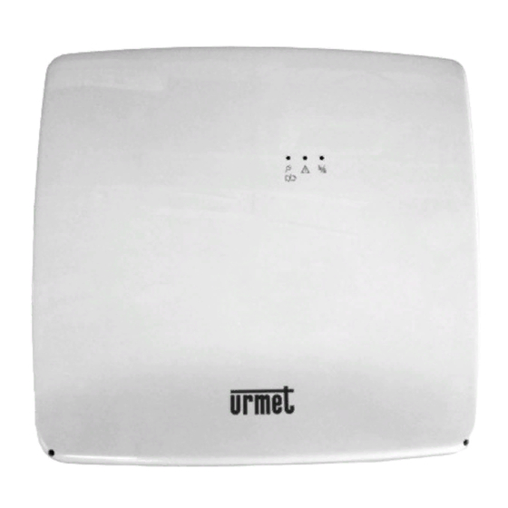
1068/005
User Manuals: urmet domus 1068/005 Control System
Manuals and User Guides for urmet domus 1068/005 Control System. We have
3
urmet domus 1068/005 Control System manuals available for free PDF download: Installation And Programming Manual, Manual, Quick Manual
urmet domus 1068/005 Installation And Programming Manual (152 pages)
REMOTE MANAGED ALARM CONTROL PANELS
Brand:
urmet domus
| Category:
Security System
| Size: 7 MB
Table of Contents
Table of Contents
2
Introduction
7
Conformity with Standard EN50131-1
7
Imq
8
How the Manual Is Organised
8
Conventions
8
Glossary
9
The 1068/005 and 1068/010 Systems
11
Main Characteristic
11
System Architecture
12
Architecture
12
Data Bus
12
Maximum System Size
13
System Connectivity
14
Connection with Remote User
16
Remote User Connection Via Urmet Secure APP (Android - IOS)
17
Remote User Connection Via a Tablet with 1068Set Android App
18
Radio Device Connection
18
Connection with an Alarm Reception Centre
19
System Components
20
1068/005 Control Panel
20
1068/010 Control Panel
21
1068/021 LCD Command Keypad
22
1067/008A 8-Input Expansion Module
22
Housing Box for Expansion Module 1067/017
23
1067/334 - 335 Electronic Key Reader
23
1067/332 Additional Keys Kit
24
1068/435 Proximity Key Reader
24
1068/432 Proximity Key Kit
25
1068/014 PSTN Module with Vocal Synthesis (Available Only with 1068/005 Control Panel)
25
1068/011 Radio Module
25
1068/458 GSM/GPRS Module with Vocal Synthesis
26
1067/014 Remote GSM Antenna
26
1068/013 IP Interface
26
1068/017 Radio Interface on Bus
27
1067/092 Supplementary Power Supply with Repeater
27
Design: Calculations and Tests
28
Sizing of the Power Supplies and the Batteries
28
Battery Sizing
28
Calculation of the Total Absorption of the System
29
Cable Sizing
29
Cables to be Used, Connections of the Shields and Installation
29
Sizing of the Power Supply Cable
30
Sizing the Power Supply and Data Transmission Bus
31
Extending the Bus with the Repeater
32
Sizing of Input/Output Connections
33
Control Criteria of the Mains Power Supply Voltage
33
Blackout Event
33
Continued Blackout Alarm
33
Restoration of the Mains Power Supply
34
Battery Management Criteria
34
Controlling the Battery with Mains Power Supply Absent
34
Battery Test in Presence of Mains
34
Self-Diagnostic Functions
34
Installation
35
Installation Procedure
35
Wiring
35
Preparing the 1068/005 - 1068/010 Control Panel
36
Installation of the 1068/005 - 1068/010 Control Panels
38
Description of the Main Parts of the 1068/005 Control Panel
38
Description of the Main Parts of the 1068/010 Control Panel
40
Installing the PSTN Module with Vocal Synthesis 1068/014 (Available Only with 1068/005 Control Panel)
42
Installing the 1068/011 Radio Module
43
Installing the 1068/013 IP Module
43
Installing the 1068/458 GSM/GPRS Module with Vocal Synthesis
44
Installation of the 1067/008A Expansion
47
Installation of the 1068/017 Radio Interface
48
Installation of the 1068/021 Keypad
49
Installation of the 1068/435 Reader
51
Installation of the 1067/092 Supplementary Power Supply (Available Only with 1068/010 Control Panel)
52
Fastening to the Wall
52
Connecting the Power Supply and Battery
52
The 1067/092 Board
53
Connections
55
Mains Power Supply Line
56
Connecting the Data Bus
57
Connecting the Supplementary Power Supplies/Repeater
58
Connecting Inputs
59
Connecting Outputs
61
Connecting the Cable for the Service Keypad
63
Connecting the Telephone Communicator
63
Example of Connection Diagram of 1068/005 Control Panel with N.C. Inputs
64
Example of Connection Diagram of 1068/010 Control Panel with N.C. Inputs
65
Example of Connection Diagram of 1068/005 Control Panel with Single BAL. Inputs
66
Example of Connection Diagram of 1068/010 Control Panel with Single BAL. Inputs
67
Example of Connection Diagram of 1068/005 Control Panel with Double BAL. Inputs
68
Example of Connection Diagram of 1068/010 Control Panel with Double BAL. Inputs
69
Example of Connection Diagram of 1068/010 Control Panel with Double Inputs
70
Example of Connection Diagram of 1067/008A Expansion with NC Inputs
71
Example of Connection Diagram of 1067/008A Expansion with SINGLE BAL. Inputs
72
Example of Connection Diagram of 1067/008A Expansion with DOUBLE BAL. Inputs
73
Commissioning
74
System Power Supply
74
Acquisitions of Bus Devices
75
Position of the Programming Buttons
75
Procedure for Acquiring the First Keypad
75
Procedure for Acquiring Bus Devices (Expansions and Readers)
76
Using the Service Keypad
76
System Commissioning
77
Navigation Menu
77
How to Access Menus
78
Free Access Menu
78
Main Menu
79
How to Enter Alphanumeric Characters
80
How to Enable the Installer
80
How to Enable the Technical Manager
80
How to Select the Language
81
LCD Info
81
Date and Time Setting
81
Zones Programming
82
Wired Input Programming
82
Wired Input Encoding
83
Input Types
83
Wired Input Customisation
84
Isolable
86
Auxiliary Functions of Intrusion Inputs (Gong, Courtesy Light and Door Opener)
87
Zone Assignment Type (and / OR)
87
AND Inputs
87
Input Programming Procedure
88
Wired Input Programming
89
Output Encoding
89
Output Types
90
Output Assignment
90
Electrical Characteristics of the Outputs
90
Output Customisations
90
Output Behaviour When the System Is Being Serviced
93
Output Programming Procedure
94
Keypad Programming
95
Function Programming Procedure
95
Zones Assignment
96
Gong Function
96
Entry Time
96
Exit Time
97
Masking
97
Name
97
Function Key
97
Reader Programming
98
LED Management
98
Programming Procedure
98
Keys
98
Key Acquisition
99
Key Deletion
99
Key Configuration
99
Advanced Programming
100
Remote Control System Code
100
Programming Procedure
100
General System Parameters (Timings)
101
Programming Procedure Times and Parameters
102
Phone Dialer and IP Interface
102
Alarm and Event Notifications
102
Phone Numbers and IP Addresses
102
Vocal Messages
102
SMS Text Messages
103
PSTN Parameters (Available Only with 1068/005 Control Panel)
103
GSM Parameters
104
GPRS Parameters
104
GSM Field Test
105
IP Parameters
105
IDP Protocol
107
IDP/IP Protocol
107
Advanced
108
Time Scheduler
109
Operating Principles
109
Programming
110
Deleting a Command
110
System Test
111
Input Test
111
Output Test
111
Control Panel Battery Test
111
Call or SMS Test
111
Push Notification Sending Test
111
GSM Field Test
111
IP Interface Test
111
Supplementary Power Supply Battery Test (Available Only with 1068/010 Control Panel)
111
System Diagnostics
112
Final Tests
112
User Training
112
Programming with Tablet
113
Prerequisites
113
Tablet Requirements
113
Enabling Requirements
113
File Types
113
Saving Data on Micro SD Card
114
How to Restore Data on the Control Panel
114
Maintenance Menu
115
How to View Device Addresses
115
How to View the Firmware Release of Devices
115
How to Upgrade Bus Device Firmware from Menu
115
Upgrade Files
115
Updating System Firmware from Keypad
116
System Firmware Upgrade from 1068Set App
117
Reset Default
118
Reset Factory Settings
118
System Log
118
How to Interpret Viewed Data
119
How to Browse the System Log
119
How to Browse the EN50131 Event Log (Available Only with 1068/010 Control Panel)
120
How to Delete the System Log
120
How to Delete the EN50131 Event Log (Available Only with 1068/010 Control Panel)
120
Tables
121
Vocal Alarm Messages and SMS
121
Alarm Sending Types
122
Remote Control Functions
122
Factory Settings
125
System Code
125
Zones
125
Users
125
Keys
125
General Parameters and Times
126
Control Panel Inputs
126
Control Panel Outputs
127
Expansion Module Inputs
128
Expansion Outputs
128
Keypad Inputs
129
Radio Module/Interface Inputs
129
Radio Module/Interface Outputs (Sirens)
129
Reader Inputs
129
Keypad Parameters
130
Reader- Zones Assignment
130
Assignment of Radio Remote Control Keys
130
Communicator Parameters
131
Time Scheduler
132
Time Scheduler Configuration
132
Maintenance
134
Maintenance Procedure
134
Maintenance Mode Access
134
End of Maintenance
135
Adding a New Bus Device
135
Procedure for Acquiring Bus Devices (Expansions, Readers and Radio Interfaces)
135
Keypad Acquisition
136
Replacing a Radio Device
136
Replacing a Bus Device
137
Replacing the Bus Devices (Expansions, Readers and Radio Interfaces)
137
Replacing the Keypad
137
Identifying a Bus Device
137
Interrogating a Bus Device
137
Searching for and Identifying a Device
138
Deleting a Bus Device
138
Deleting 1068/017 RADIO Interface or 1068/011 RADIO Module
138
Enabling/Disabling the 1068/011 Radio Module
139
Enabling/Disabling the 1068/017 Radio Interface
139
Radio Connection Test
139
Configuring Radio Parameters
140
Device Supervision
140
Jamming
140
Enable
141
Module Supervision
141
Acquisition of a New Radio Device
141
Deleting a Radio Device
141
Reset Factory Settings
142
Software Partial Reset
142
Codes Software Reset
143
Radio Module Software Reset
143
Installer Hardware Code Reset
143
1068/013 Interface Hardware Reset
143
Hardware Reset to Factory Settings
143
Wired Device Hardware Reset
143
Wired Keypad Hardware Reset
144
Replacing the Battery
145
Turning off the Entire System
145
Technical Specifications
146
1068/005 Control Panel
146
1068/010 Control Panel
147
1067/092 Supplementary Power Supply with Repeater
148
1068/021 Command Keypad LCD
149
1067/334 - 1067/335 Electronic Key Reader
149
1068/435 Proximity Reader
149
1067/008A 8-Input Expansion Module
150
1068/014 PSTN Module with Vocal Synthesis (Available Only with 1068/005 Control Panel)
150
1068/458 GSM/GPRS Module with Vocal Synthesis
150
1068/013 IP Interface
150
Advertisement
urmet domus 1068/005 Manual (52 pages)
Brand:
urmet domus
| Category:
Music Mixer
| Size: 1 MB
Table of Contents
Table of Contents
2
Introduction
5
Conventions
5
Control Devices
6
1068/005 - 1068/010 Control Panel
6
1068/021 LCD Command Keypad
7
Status Icons in the Display
8
Zone Status
9
1067/334 - 1067/335 Electronic Key Reader
10
1068/435 Proximity Key Reader
10
System Basic Management
11
Keypads Customisation
11
LCD Info
11
How to Set the Buzzer Volume
12
How to Set the Display Contrast
12
How to Set Backlighting
12
Date and Time Setting
12
Setting Procedure
13
Partial or Total Setting with 1068/021 Keypad
13
Partial and Total Setting with Electronic or Proximity Key
14
Unsetting Procedure
15
Partial or Total Unsetting with 1068/021 Keypad
15
Partial and Total Unsetting with Electronic or Proximity Key
16
System Status Information
17
How to View System Status
17
How to View Isolated or Inhibited Inputs
17
How to Examine the Alarms Memory
17
How to Delete the Alarms Memory
17
How to Examine the Tampers Memory
18
How to Delete the Tampers Memory
18
How to Examine the Fault and Anomaly Memory
18
How to Delete the Fault Memory
18
How to Postpone Automatic Setting
18
System Activation Failure
19
Blocking Conditions
19
Conditions that Can be Inhibited
19
Conditions that Can be Inhibited on Inputs
19
Example of Overriding
20
Impossibility to Override the Prevention of Setting with Open Inputs
20
Alarms, Events and Indications
21
Description of Signalling Events in the Log
21
Advanced System Management
25
System Access Codes
25
Default Access Codes
26
Change Code
26
How to Reset an Access Code
26
Entering an Invalid Code or Using an Invalid Key
26
Menu
27
How to Access Menus
27
How to Navigate the Menus
27
Free Access Menu
28
Main Menu
29
How to Enter Alphanumeric Characters
30
Enabling and Disabling
30
How to Enable the Installer
31
How to Enable the Technical Manager
31
How to Enable a User
31
How to Enable a Key
32
How to Enable the Time Scheduler
32
How to Enable Remote Access
32
Enabling Remote Unsetting
32
Enabling Anti-Thieft Function
33
Enabling Hold-Up Function
33
How to Disable the Installer
33
How to Disable a User
33
How to Disable a Key
33
How to Disable the Technical Manager
33
How to Disable the Time Scheduler
33
How to Disable Remote Access
34
Disabling Remote Unsetting
34
Disabling Anti-Thieft Function
34
Disabling Hold-Up Function
34
SYSTEM Log
35
How to Interpret Viewed Data
36
How to Browse the System Log
36
How to Browse the EN50131 Event Log (Available Only with 1068/010 Control Panel)
36
Users
37
Prerequisites
37
How to Assign a User
37
How to Program a Descriptive User Name
37
Phone Dialer and Ip Interface
38
Alarm and Event Notifications
38
Phone Numbers and IP Addresses
39
How to Edit a Phone Number
39
Changing the IP Address and Port
39
Zones Assignment Modification
39
Changing the Sending Mode
40
Network Modification
40
Changing Events to be Notified
41
SMS Messages
41
Editing Texts for SMS Messages
41
User Remote Control
42
Activation and Deactivation of Outputs with SMS
42
Deviation of Incoming SMS Messages
42
Activation of Outputs with Free of Charge Calls
42
Remote Control with Guided Voice Menu
43
Calling the PSTN Answering Machine in the Absence of an Answering Machine (Available Only with 1068/005 Control Panel)
43
Calling the PSTN Answering Machine with an Answering Machine Available (Available Only with 1068/005 Control Panel)
43
Calling the GSM Answering Machine
43
Functions of the Guided Voice Menu
43
List of DTMF Commands for Vocal Answer Machine
44
System Test
45
Periodical Tests
45
Input Test
45
Output Test
45
Control Panel Battery Test
46
Call Test or SMS
46
Push Notification Sending Test
46
GPRS/GSM Field Test
47
IP Interface Test
47
Supplementary Power Supply Battery Test (Available Only with 1068/010 Control Panel)
47
System Sheet
48
Installation Details
48
Zones Table
48
Table of Programmed Phone Numbers
49
Quick Guide to Remote Control
50
urmet domus 1068/005 Quick Manual (40 pages)
Brand:
urmet domus
| Category:
Security System
| Size: 4 MB
Advertisement
Advertisement
Related Products
urmet domus 1068/010
urmet domus 1067/336
urmet domus 1093/534P
urmet domus 1093/538P
urmet domus 1093/536P
urmet domus 1092/662
urmet domus 1092/661
urmet domus 1039/70
urmet domus iPerTAlk 1375/13
urmet domus 1068/011
urmet domus Categories
Intercom System
Security Camera
Control Unit
Security Sensors
Monitor
More urmet domus Manuals
Login
Sign In
OR
Sign in with Facebook
Sign in with Google
Upload manual
Upload from disk
Upload from URL