Sign In
Upload
Manuals
Brands
Unitec Manuals
Intercom System
Portal TI+
Unitec Portal TI+ Wash System Manuals
Manuals and User Guides for Unitec Portal TI+ Wash System. We have
2
Unitec Portal TI+ Wash System manuals available for free PDF download: Owner's Manual, Installation Manual
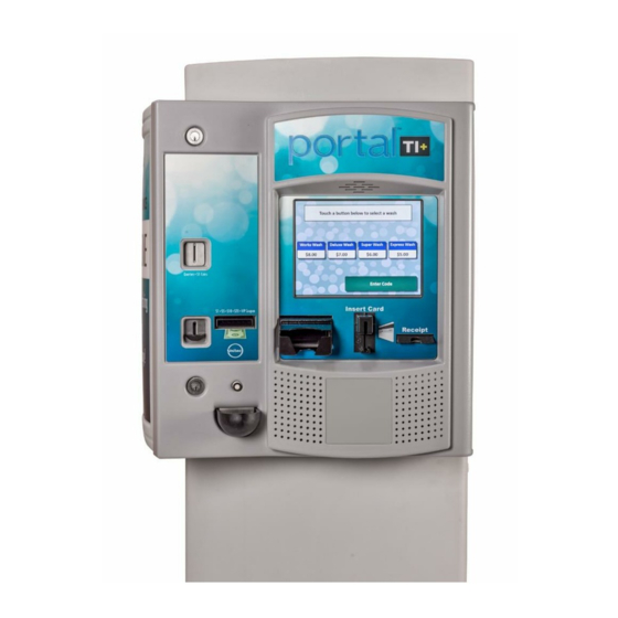
Unitec Portal TI+ Owner's Manual (101 pages)
Car wash payment system
Brand:
Unitec
| Category:
Payment Terminal
| Size: 4 MB
Table of Contents
Table of Contents
5
1 Introduction
11
2 Login
11
Figure 1. Portal TI Login Screen
11
Figure 2. Password Change Screen
12
Figure 3. Site Summary Screen
14
3 Set-Up Functions
15
General Site Information
15
Product Programming
15
Portal Programming
15
General Information
15
Operating Schedule
16
Wash Dispensing
16
Added Services Dispensing
16
Wash Interface
16
Programming Hardware Devices
16
User Interface Set-Up
17
User Management
17
POS Interface
18
Sales Screen
18
4 Promotions
19
Discounts
19
Complimentary Washes
19
Figure 4. Promotions - Main Screen
19
Fundraisers
20
Scheduled Specials
20
Prize Promos
20
Promotions Setup
21
Figure 5. Promotions Main Screen
21
Figure 6. Prize Discount Setup Screen
22
Prize Promo Setup
22
Figure 7. Prize Voucher Setup Screen
23
Promotions Setup
23
Figure 8. Edit Discount Screen
24
Figure 9. Promotions Washes
24
Promotions Reports
25
Status Report
25
Usage Report
25
Figure 10. Sample Promotions Status Report
25
5 House Accounts
26
Prepaid Accounts
26
Figure 11. Sample Promotions Usage Report
26
Subscription Accounts
27
Loyalty Accounts
27
Fleet Accounts
28
Account Programs
28
Pre-Paid Account Program Setup
29
Figure 12. Account Program Screen
29
Figure 13. Pre-Paid Account Program Edit Screen
29
Subscription Account Program Setup
30
Figure 14. Subscription Account Program Edit Screen
30
Accounts
31
Prepaid and Subscription Accounts
31
Loyalty Accounts
32
Figure 15. Prepaid Account Edit Screen
32
Fleet Accounts
33
Figure 16. Loyalty Account Setup Screen
33
Figure 17. Edit Fleet Account
34
Account Reports
35
Status Report
35
Figure 18. Edit Account User
35
Listing Report
36
Figure 19. Sample House Account Status Report
36
Loyalty Report
37
Fleet Report
37
Figure 20. Sample Account Loyalty Report
37
Figure 21. Sample House Account Fleet Report
38
Sales Report
40
Figure 22. Account Sales Report
40
Account Transaction Report
41
Figure 23. Account Transaction Report
41
6 Reports
42
Site Revenue Report
43
Figure 24. Sample Site Revenue Report
44
Sales Report
45
Figure 25. Sample Sales Report
45
Cash Report
47
Figure 26. Sample Cash Report
47
Transaction Report
48
Figure 27. Sample Transaction Report
49
Figure 28. Sample Transaction Details
49
Code Listing Report
50
Figure 29. Sample Code Listing Report
50
7 Sales
51
Figure 30. Sales Screen
51
Figure 31. Purchase Wash Package Screen
52
Figure 32. Wash Purchased Screen
52
Figure 33. Account Purchase
53
Figure 34. Reload Account Screen
54
Figure 35. Reloaded Account Screen
54
Figure 36. Rewash Selection Screen
55
Figure 37. Rewash Code Issued Screen
55
Figure 38. Report Date Selection Screen
56
8 Utilities
57
Figure 39. System Utilities Screen
57
Enable Support Mode
58
Figure 40. Enable Support Mode Screen
58
Database Management
59
Compact and Cleanup Database
59
Figure 41. Database Utility Screen
59
Figure 42. Database Compact and Clean Screen
59
Delete Old Codes
60
Automatic Backups Schedule for Server
60
Figure 43. Delete Old Codes Screen
60
Figure 44. Automatic Backup Settings Screen
60
Restore Factory Defaults
61
Figure 45. Files Screen
62
Files
62
9 Maintenance Functions
63
Figure 46. Portal Maintenance Screen
63
Cash Functions
64
Figure 47. Cash Deposit Screen
64
Figure 48. Cash Removal Screen
65
Figure 49. Shutdown Screen
66
Shutdown
66
10 Component Operation and Maintenance
67
Component Layout
67
Portal TI Door Assembly
67
Inside the Portal TI Door Assembly
68
Figure 50. Portal TI Front View Visible Components
68
Inside the Portal TI Unit Case
69
Figure 51.Components Inside the Portal TI Door
69
Inside the Portal TI Cash Vault
70
Figure 52. Block Diagram of Components Inside the Portal TI Case
70
System Cabling
71
Cleaning and General Maintenance
71
Figure 53. Block Diagram of Components Inside the Cash Vault
71
Security Devices
72
Setting the Alarm
72
Shock Sensor
73
Bill Dispenser
73
Bill Dispenser Location
73
Bill Dispenser Security
73
Figure 54. Bill Dispenser Location
73
Bill Dispenser Operations Components
74
Clearing Bill Dispenser Jams
74
Figure 55. Bill Dispenser Parts
74
Figure 56. Manual Knob and Transportation Area
75
Loading the Bill Dispenser
76
Figure 57. Removing a Jammed Bill
76
Figure 58. Loading Instructions
77
Figure 59. Loading the Bill Dispenser
78
Maintaining the Bill Dispenser
79
Figure 60. Bill Dispenser Pick Roller Cleaning
79
Figure 61. Bill Dispenser Sensor Cleaning
80
Bill Validator
81
Mars Bill Validator
81
Figure 62. Mars Bill Validator/Stacker
81
Figure 63. Mars Bill Validator-Top View
82
Figure 64. Mars Bill Stacker Replacement
83
Figure 65. Mars Flash Code LED
84
Figure 66. Mars with Lower Housing
86
Figure 67. Mars with Lower Housing Removed
86
Card Reader
87
Cleaning the Card Reader
87
Troubleshooting the Card Reader
87
Coin Acceptor
88
Coin Acceptor Cleaning and Maintenance
88
Programming the IDX Acceptor
88
Programming the IDX to Accept $1 Coins
89
Figure 68. Outside/ Inside of the IDX
89
Programming the IDX to Accept Quarters
90
Site-Specific Tokens
90
Erasing IDX Programming
91
Coin Hopper
91
Removing the Hopper
92
Filling the Hopper
92
Figure 69. Block Diagram of the Hopper Cage
92
Changing the Dispense Value
93
Figure 70. Remove Hopper Coin Bucket
94
Figure 71. Hopper View - Removing the Hopper - Cube Top
94
Figure 72. Hopper View - Top Removed
95
Figure 73. Dispensing Wheel Removed
95
Figure 74. Guide Arm Cover Removed
96
Credit Modem
97
Proximity Sensor
97
Figure 75. Hopper View - Coin Exit Opening and Chute
97
Sound System
98
Troubleshooting
98
Testing Door Switches
98
Thermal Printer
100
Figure 76. Hecon Printer
100
Clearing a Paper Jam
101
Manually Printing a Self Test
101
Replacing the Printer Paper
101
The Token Bucket
101
Appendix A: Themes
101
Advertisement
Unitec Portal TI+ Installation Manual (50 pages)
Car Wash Entry System
Brand:
Unitec
| Category:
Intercom System
| Size: 1 MB
Table of Contents
Table of Contents
3
1 Site Planning and Preparation
5
General
5
Mounting Options
5
Positioning the Portal
5
In-Bay Applications
5
Express Wash Applications
6
Figure 1. Portal Installation at the Wash Entrance
6
Figure 2. Frame Location for Curb Mount
6
Figure 3. Express Exterior Island
7
Electrical Preparation
8
Conduit Installation
8
Figure 4. Conduit Runs
8
Figure 5. Portal Base Dimensions
9
Power Requirements
10
Site Wiring Requirements
10
2 Mechanical Installation
11
Hardware Required
11
Recommended Tools
11
Mechanical Installation Tools
11
Base Installation
12
Figure 6. Base Installed in Concrete Pad
12
Brick-In Installation
13
Brick-In Mounting Options
13
Positioning the Portal
14
Figure 7. Bricked-In Mounting Options
14
Figure 8. Positioning the Adaptor Plate
15
Figure 9. Door Positioning Options
16
Brick-In Guidelines
17
Figure 10. Portal Mounting for Bricked-In Installation
17
Figure 11. Portal Brick-In with Adaptor Plate
18
Figure 12. Portal Brick-In with Adaptor Plate on Base Frame
19
3 Electrical Installation
21
Hardware Required
21
Recommended Tools
21
General
21
Connecting Power
22
Figure 13. Portal Interior
22
Figure 14. Inside the AC Connector
23
Figure 15. Line - Neutral - Ground Connections
23
Network Connection
24
Figure 16. Network Port Location
24
Telephone Cable
25
Figure 17. 2-Port Telephone Line Splitter
25
Wash Control Wiring
26
Overview
26
Figure 18. Telephone Line Connection (for Data Modem)
26
Wiring the Wash Relay Interface
27
Figure 19. Wash I/O Board Connectors
28
Figure 20. 10-Pin Phoenix Connector
28
Wiring the Wash-In-Use Interface
29
Figure 21. 6-Pin Phoenix Connector
30
Intercom Systems
31
Overview
31
Intercom Connections
31
Intercom Adjustments
31
Connection Overview
32
Figure 22. Intercom Component Locations on the Display IO Board
32
Figure 23. Four-Wire Intercom Configuration
33
Figure 24. Three-Wire Intercom Configuration
33
Figure 25. Two-Wire Intercom Configuration
33
Camera Connection
34
Gate Wiring
34
Connecting the Reach Free ID Option
34
Figure 26. BNC Male Plug for Camera Connection
34
4 System Test
35
Appendix A. Dimensional Schematic of the Portal TI
37
Appendix B. Iptran Installation
39
Appendix C. Portal Networking
42
Appendix D. Installing a Print Server
48
Appendix F. Installation of the External POS
50
Advertisement
Related Products
Unitec POWER-STATION BASIC
Unitec PREMIUM
Unitec POWERSTATION PLUS
Unitec Categories
Smoke Alarm
Drill
Automobile Accessories
Air Compressor
Saw
More Unitec Manuals
Login
Sign In
OR
Sign in with Facebook
Sign in with Google
Upload manual
Upload from disk
Upload from URL