Sign In
Upload
Manuals
Brands
Unipower Manuals
Portable Generator
Sageon III
Unipower Sageon III DC Power System Manuals
Manuals and User Guides for Unipower Sageon III DC Power System. We have
1
Unipower Sageon III DC Power System manual available for free PDF download: Product Manual
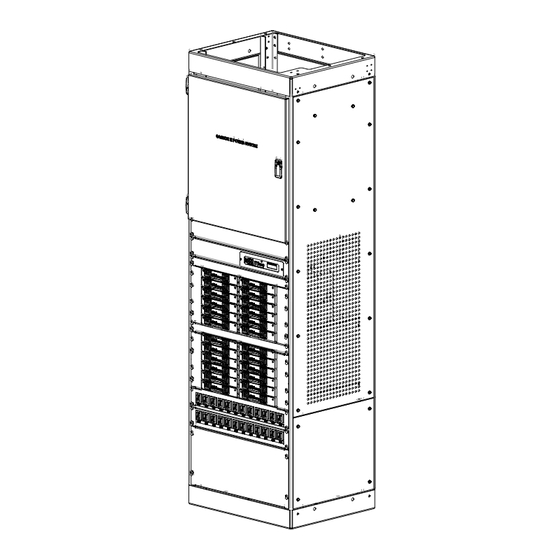
Unipower Sageon III Product Manual (109 pages)
Power System
Brand:
Unipower
| Category:
Portable Generator
| Size: 6.78 MB
Table of Contents
Table of Contents
10
Figure 1-1 Sageon III Power System
12
Figure 1-2 Simplified Block Diagram, -48V Power System
14
Figure 1-3 600A Plant
17
Figure 1-4 1200A Plant
17
Table 2-1 Wire Sizing
24
Table 2-2 Torque Specifications, Steel Fasteners
25
Figure 2-1 Power System Dimensions
26
Figure 2-2 Plant Base
27
Figure 2-3 Return Bus Locations
28
Table 2-3 Circuit Breaker Selection, Ac Power
29
Figure 2-4 Ac Input Cabling with Rectifier On/Off Option
29
Figure 2-5 Battery Charge Bus and Battery Return Bus Locations
30
Figure 2-6 Load Supply and Return Cabling
31
Figure 2-7 Distribution Group Identities and Locations
32
Figure 2-8 Distribution Area, Top View, Am1 Type Breaker Dist. Shown
32
Figure 2-9 Distribution Cable Routing
33
Figure 2-10 Am1 Type Distribution Lugging
34
Figure 2-11 Gj1 Type Breaker Distribution Assemblies, Typical
35
Figure 2-12 Gj1 Type Breaker Distribution Wiring
35
Table 2-4 Battery Temperature Sensor Connections
36
Figure 2-13 Interface Board, Customer Alarm Connections
36
Figure 2-14 Temperature Sensor Location
37
Table 2-5 Battery Current Transducer Connections
38
Figure 2-15 Typical Battery Current Transducer
38
Figure 2-16 Rectifiers
39
Figure 2-17 Sageon III Power System
41
Figure 2-18 Connections on Controller Backplane
42
Figure 2-19 Temperature Concentrator Board
42
Figure 2-20 Sageon III Board Locations
43
Figure 3-1 Single Phase Feed (Phase to Neutral)
46
Figure 3-2 Single Phase Feed (Phase to Phase)
47
Figure 3-3 Split Single Phase Feed (Phase to Neutral)
48
Figure 3-4 Y-Three Phase Feed -Connected Rectifiers (Phase to Phase)
49
Figure 3-5 Y-Three Phase Feed (Phase to Neutral)
50
Figure 3-6 -Three Phase Feed (Phase to Phase)
51
Figure 3-7 Surge Protection
52
Figure 3-8 Multiple Alarm Board
52
Figure 3-9 Battery Distribution Module (Bdm)
54
Table 4-1 Summary of Default System (Scu) Parameters
56
Figure 4-1 Operator Panel
58
Table 4-2 Reading Operator Panel System Status Leds
59
Table 4-3 Operator Panel Annunciated Alarm Messages
60
Table 4-4 Sbm Boards Needed for Various Battery Configurations
74
Figure 5-1 Network Connections
82
Table 6-1 Alarm Messages and Error Codes
87
Table 6-2 Rectifier Led Codes
87
Figure 6-1 Replacing the Scu (Sageon III Control Unit)
88
Figure 6-2 Removing Rectifier Module
92
Figure 7-1 Distribution Location by Tier and Group
93
Table 7-1 Installable Distribution Types by Tier and Group
94
Figure 7-2 Distribution Area, Left Side
94
Figure 7-3 Distribution Area, Right Side
95
Figure 7-4 Orientation of Distribution Assemblies, -48V Systems
96
Installing the Kit
97
Figure 7-5 Typical Installation of Am1 Distribution
97
Figure 7-7 Gj1 Distribution Kit (W/ Breaker Kit)
100
Figure 8-1 Am1 Type Breaker Kit Components
101
Nut, Hex
101
Quantity 1 2
101
Figure 7-6 Distribution Assemblies, Gj1
98
Bolt, Hex Head, 3/8-16 X
99
Washer, Bevel
99
Washer, Flat 5/16
99
Figure 8-2 Am1 Type Breaker (Shown) Kit Installation
102
Figure 8-3 Gj1 Type Breaker Kit Components
103
Figure 8-4 Gj1 Type Breaker Kit Installation
104
9.0 Spare and Replacement Parts
105
Table 9-1 Parts List
105
Advertisement
Advertisement
Related Products
Unipower SAGEON VIGIL
Unipower Sageon PSMC I
Unipower Sageon II
Unipower Sageon Micro Power Module
Unipower Sageon II Bulk
Unipower SLI 15
Unipower Categories
Power Supply
Power distribution unit
Inverter
Battery Charger
Measuring Instruments
More Unipower Manuals
Login
Sign In
OR
Sign in with Facebook
Sign in with Google
Upload manual
Upload from disk
Upload from URL