
Summary of Contents for Unipower Sageon III
- Page 1 Sageon III™ Power System Product Manual 600A 1200A UNIPOWER, LLC 65 Industrial Park Rd Dunlap, TN 37327 Phone: +1-954-346-2442 PM 990-8800-00, Rev. 9 Toll Free: 1-800-440-3504 Web site – www.unipowerco.com...
- Page 2 If it is determined that the equipment should be returned to UNIPOWER, ask the delivering carrier to send the packages back to UNIPOWER at the delivering carrier's expense.
- Page 3 Front Matter Sageon III Power System NAMEPLATE Each piece of UNIPOWER equipment is identified by a part number on the nameplate. Please refer to this number in all correspondence with UNIPOWER. INITIAL SETTINGS All equipment is shipped from our production area fully checked and adjusted. Do not make any adjustments until you have referred to the technical reference or product manual.
- Page 4 III Power system. It consists of nine chapters with a packet of drawings following the text. The drawings supplement the provided descriptions and procedures. Thank you for purchasing the Sageon III Power system. We at UNIPOWER, LLC are proud of the quality of our products and welcome any suggestions to further improve our design to fit your needs.
- Page 5 For 5/16” and 8mm Battery Hardware (Includes harness & flat washers) 385.6151.05 For 3/8” and 10mm Battery Hardware (Includes harness & flat washers) 385.6151.06 For 1/2" and 12mm Battery Hardware (Includes harness & flat washers) 385.6151.07 Sageon III Power Plant Parts List Continues… PM990-8800-00, Rev. 9...
- Page 6 Temperature Sensor 19’ (6M) 385.5941.06 Temperature Sensor 50’ (15M) 385.5941.15 AM1 Plug-In Bullet Circuit Breaker Kits (for Sageon III) (Kits include breaker, bus adaptor & return mounting hardware) 1 Ampere, AM1 Series Breaker, 1 Position 274.3830.01 3 Ampere, AM1 Series Breaker, 1 Position 274.3830.03...
- Page 7 Front Matter Sageon III Power System Descriptions Part Numbers GJ1 Bolt-In, Single-pole, Circuit Breaker Kits (includes hardware) (Requires SAGEON3.E03, E04, E05) 100 Ampere, GJ1 Series Breaker, 1 Position 274.3833.100 125 Ampere, GJ1 Series Breaker, 1 Position 274.3833.125 150 Ampere, GJ1 Series Breaker, 1 Position 274.3833.150...
- Page 8 Sageon III Power System Front Matter Table of Contents 1.0 INTRODUCTION................................... 1-1 1.1 PRODUCT DESCRIPTION ................................1-1 1.2 SPECIFICATIONS ..................................1-4 1.2.1 Power system Physical Specifications............................1-4 1.2.2 Power system Environmental Specifications ........................... 1-4 1.2.3 Power system Electrical Specifications ............................ 1-5 1.2.4 General Specifications ................................
- Page 9 6.3 TROUBLESHOOTING ................................. 6-2 6.3.1 Reading Rectifier Status Led Codes ............................6-2 6.4 REPLACING A RECTIFIER ................................ 6-2 6.5 REPLACING THE SAGEON III CONTROL UNIT (SCU) ......................6-3 6.5.1 Configuration Considerations..............................6-3 6.6 REPLACING AN AC BACK PLANE BOARD ........................... 6-3 6.7 TROUBLESHOOTING .................................
-
Page 10: Table Of Contents
FIGURE 4-1 OPERATOR PANEL ................................ 4-3 FIGURE 5-1 NETWORK CONNECTIONS ............................5-1 FIGURE 6-1 REPLACING THE SCU (SAGEON III CONTROL UNIT) .................... 6-3 FIGURE 6-2 REMOVING RECTIFIER MODULE ..........................6-7 FIGURE 7-1 DISTRIBUTION LOCATION BY TIER AND GROUP ....................7-1 FIGURE 7-2 DISTRIBUTION AREA, LEFT SIDE .......................... - Page 11 Front Matter Sageon III Power System List of Tables TABLE 2-1 WIRE SIZING ................................... 2-3 TABLE 2-2 TORQUE SPECIFICATIONS, STEEL FASTENERS ..................... 2-4 TABLE 2-3 CIRCUIT BREAKER SELECTION, AC POWER ......................2-8 TABLE 2-4 BATTERY TEMPERATURE SENSOR CONNECTIONS .................... 2-15 TABLE 2-5 BATTERY CURRENT TRANSDUCER CONNECTIONS ...................
-
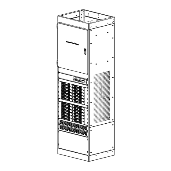
Page 12: Figure 1-1 Sageon Iii Power System
1 through 9. 1.1 PRODUCT DESCRIPTION The Sageon III Power system is intended for Cellular, PCS, and other applications that demand stable, reliable, high current, DC operating power. Sageon III can supply the voltage and currents shown in the following table. - Page 13 Refer to SageView help for configuring these relays. Block Diagram Description A simplified block diagram of a 48V Sageon III Power System is shown in Figure 1-2. Single-phase or three-phase power is supplied from the user’s AC electrical service panel.
-
Page 14: Figure 1-2 Simplified Block Diagram, -48V Power System
Sageon III Power System Introduction FIGURE 1-2 SIMPLIFIED BLOCK DIAGRAM, -48V POWER SYSTEM PM990-8800-00, Rev. 9... - Page 15 The operator panel provides user access to the configuration and monitoring capabilities of the SCU. For security, a parameter lock feature is included and PC access can require a password. A PC that is to be connected to the Sageon III Power System must have the optional SageView software installed and operating.
- Page 16 Sageon III Power System Introduction Altitude ............9,800 feet (3,000m); Contact the factory for derating above specification Heat Dissipation ..........1070 BTU/Hr. maximum @ full load, per Rectifiers Cooling Distribution ..........Convection cooling Rectifier Modules ........Fan forced air, front to back with built-in over temperature power limiting Audible Noise ..........
-
Page 17: Figure 1-3 600A Plant
Introduction Sageon III Power System Immunity continues… Immunity: Category Tested To Criterion Surge Protection ANSI C62.41-1991 category B3 – AC lines (Combination Wave 6 kV/3 kA; Ring Wave 6 kV/500A) IEC 61000-4-5; EN 61000-4-5: (Impulse) (6 kV/3 kA Common Mode [CM] on AC lines) (6 kV/3 kA Differential Mode [DM] on AC lines) (0.5 kV/0.25 kA CM &... - Page 18 External Protective Device ....Thermal circuit breaker (input) Fully Protected ........440 Vac, indefinitely Over-Voltage Shutdown ......300 Vac Under-Voltage Shutdown ...... 85 Vac Service ............Hot swappable (i.e. Can be installed in or removed from an operating Sageon III Power System) Output, 48V Rectifiers Float Voltage Nominal ...........
- Page 19 Introduction Sageon III Power System Safety Specifications The following were used as guidelines in the specifications of all components and wiring, with particular attention to safety ratings and OI-28 flammability requirements. • Underwriters Laboratory Standards of Safety (UL 60950) •...
- Page 20 Sageon III Power System Introduction 1.4 REFERENCE PUBLICATIONS DOCUMENT TITLE NUMBER ANSI C 39.1 Requirements for Electrical Analog Indicating Instruments ANSI T1.311-1991 DC Power Systems - Telecommunications Environment Protection ANSI/IEEE C 62.41- IEEE Guide for Surge Voltages in Low-Voltage AC Power Circuits, ANSI...
- Page 21 Toll Free: 1-800-440-3504 Web site – www.unipowerco.com When contacting UNIPOWER, please be prepared to provide: The product model number, spec number, S build number, and serial number - see the equipment nameplate on the front panel Your company’s name and address...
- Page 22 Rectifier Position Address Each rectifier position is factory-assigned a unique, sequential address within the Sageon III Power System. The System operator uses this address when configuring and operating the System to identify and access a specific Rectifier. The AC Backplane board at each rectifier position has one DIP switch on which the address is set.
- Page 23 Torque Specifications – The torque specification table in this subsection is referenced in procedures that include hardware. Tools And Accessories To install the Sageon III Power system, the following user-supplied items should be available. • Equipment to move Power system to installation site •...
-
Page 24: Table 2-1 Wire Sizing
Sageon III Power System Installation Selecting and Sizing DC Power Cables Protective circuits, overall system performance, and safety depend on the proper sizing of DC cables for current and acceptable DC voltage drop. The minimum size allowable is the larger of the wire size per the National Electrical Code or the calculated wire size. -
Page 25: Table 2-2 Torque Specifications, Steel Fasteners
Installation Sageon III Power System Torque Specifications Proper plant performance requires that the hardware employed during installation be tightened securely but not over tightened. Use a torque wrench to ensure that hardware is tightened to the specification provided in Table 2-2. -
Page 26: Figure 2-1 Power System Dimensions
Floor Mounting: The Power system must be permanently anchored. Install one anchor in each floor corner. Mounting slots are provided in each corner to allow for ease of anchoring. Mark and drill holes where shown in Figure 2-2. UNIPOWER offers several seismic zone hardware kits. -
Page 27: Figure 2-2 Plant Base
Installation Sageon III Power System FIGURE 2-2 PLANT BASE Caution: Do not block rear panel grille. A blocked grille will limit the flow of cooling air and can result in equipment overheating and failure. Minimum clearance behind the Plant is 2" (5 cm). -
Page 28: Figure 2-3 Return Bus Locations
Sageon III Power System Installation Plant Rack: Ground the Power system rack to the site’s central frame ground applicable in accordance with codes and the customer’s standard practice. Unthreaded holes for bolting an earth/safety ground wire to the rack are provided in the top and bottom, both on rear. -
Page 29: Figure 2-4 Ac Input Cabling With Rectifier On/Off Option
Installation Sageon III Power System Label each breaker position and both ends of each AC power cable with the Power system number and rectifier position address to which it will be connected (e.g. P1R1 = Power system 1, Rectifier position address 1). Rectifier positions are numbered from top to bottom as shown below. -
Page 30: Figure 2-5 Battery Charge Bus And Battery Return Bus Locations
Sageon III Power System Installation 2.6 CONNECTING BATTERY CABLES Routing the stiff, heavy gauge battery cables is difficult. Two people may be needed. Exercise extreme caution to avoid a short circuit across the battery terminals. WARNING Arcing hazard Arcing can cause equipment damage, load interruptions, and personal injury. -
Page 31: Figure 2-6 Load Supply And Return Cabling
Installation Sageon III Power System At the Power system, install appropriate lugs on cables. CAUTION a) Secure the negative cable to the battery charge bus. b) Secure the positive cable to the battery return bus. NOTE: See table 2-2 for torque specifications. -
Page 32: Figure 2-7 Distribution Group Identities And Locations
Sageon III Power System Installation Distribution is organized by Tier (1-3), Group (A & B) and position (1-10). See Figure 2-7. The Breaker/Fuse Layout label on the rear of the distribution area door is for recording breaker/fuse current rating and part number. -
Page 33: Figure 2-9 Distribution Cable Routing
Installation Sageon III Power System Load Return Cables Terminate all load return cables at the return bus (loads) shown in Figure 2-6. This bus is located on the right of the distribution area and consists of up to three vertically mounted plates. The plates have pairs of 1/4" and 3/8" threaded studs for 2-hole lugging. Use the 1/4"... -
Page 34: Figure 2-10 Am1 Type Distribution Lugging
Sageon III Power System Installation Select a starting point, Tier 1, Group A Position 1 is recommended. Use appropriate lugs on the load supply and return cables. Dress the cable as shown in Figure 2-9, toward the front or rear of the rack according to the orientation of the distribution assembly. -
Page 35: Figure 2-11 Gj1 Type Breaker Distribution Assemblies, Typical
Installation Sageon III Power System Load Supply Cables, GJ1 Type Breaker Distribution When ordered, GJ1 type distribution assemblies are always the upper-most distribution assemblies in a plant since no more distribution can be installed above a GJ1 type assembly. Cable routing and connection are shown in Figure 2-12. Connect the top breaker terminals to user loads. -
Page 36: Figure 2-13 Interface Board, Customer Alarm Connections
Temp Board and the sensors and wires then coiled and tied to the return bus. If not ordered with the Sageon III Power System, an Ambient and up to four Battery Temperature Sensor can be ordered separately. Installing the Sensors: Open the distribution door and locate the Multiple Battery Temperature Board. -
Page 37: Figure 2-14 Temperature Sensor Location
SCU to limit the recharge current to the battery string in order to extend battery life; and set a fixed, repeatable discharge current for battery discharge tests. Install one battery current transducer per battery string (up to four transducers). If not ordered with the Sageon III Power System, a Battery Current Transducer Kit is available. -
Page 38: Figure 2-15 Typical Battery Current Transducer
Open the distribution door and locate the supplied battery current transducer cables; there is one cable per transducer. The 4- conductor cables are coiled and tied to the return bus (loads) in the distribution area of the Sageon III Power System. The length of the supplied cables is 4 ft. -
Page 39: Figure 2-16 Rectifiers
2.12 SITE MONITOR SYSTEM (OPTION) The Site Monitor System is used to monitor the status of equipment external to the Sageon III Power System. It has 12 digital inputs, 8 analog inputs, and 4 form-C user assignable alarm relay contacts. Digital inputs are often used to monitor site security, such as door or window openings, or other on/off function, such as a pump switch or motor starter. - Page 40 Installation A Rectifier can be installed or removed “hot” (i.e. with AC power and DC load applied) with no interruption of Sageon III Power System service. When removing a Rectifier, there must be sufficient remaining rectifier current capacity to supply the load.
-
Page 41: Figure 2-17 Sageon Iii Power System
Modules for Monitoring Site Status and Battery Remote Communication capability, including Web- Cell Voltages (opt) based Protocols (opt) • • AC Breakers All Rectifiers and the Controller are hot-swap and plug-and-play capable FIGURE 2-17 SAGEON III POWER SYSTEM PM990-8800-00, Rev. 9 2-20... -
Page 42: Figure 2-18 Connections On Controller Backplane
Sageon III Power System Installation FIGURE 2-18 CONNECTIONS ON CONTROLLER BACKPLANE Remote communications module connection (14-way ribbon)* Auxiliary peripheral module (relays, battery cell monitor, etc) connection (16-way ribbon)* Battery (& load) distribution module connection (34-way ribbon)* Ambient temperature sensor connection... -
Page 43: Figure 2-20 Sageon Iii Board Locations
Installation Sageon III Power System FIGURE 2-20 SAGEON III BOARD LOCATIONS PM990-8800-00, Rev. 9 2-22... - Page 44 Sageon III Power System Commissioning 3.0 COMMISSIONING This chapter describes commissioning a Power System. Individual system settings can vary widely so it is important that those performing the commissioning fully understand the system at hand. Modify these procedures as needed to accommodate the installed equipment and your company’s commissioning procedures.
- Page 45 Repeat Steps 7 through 10 until all Rectifiers are on-line and taking load. As Rectifiers are brought on-line, the load may be increased. 10. At the operator panel, verify that each Rectifier is sharing current and the Sageon III Power System voltage is set to the desired Float voltage, generally –54.2 Vdc ±½ volts.
-
Page 46: Figure 3-1 Single Phase Feed (Phase To Neutral)
Sageon III Power System Commissioning FIGURE 3-1 SINGLE PHASE FEED (PHASE TO NEUTRAL) PM990-8800-00, Rev. 9... -
Page 47: Figure 3-2 Single Phase Feed (Phase To Phase)
Commissioning Sageon III Power System FIGURE 3-2 SINGLE PHASE FEED (PHASE TO PHASE) PM990-8800-00, Rev. 9... -
Page 48: Figure 3-3 Split Single Phase Feed (Phase To Neutral)
Sageon III Power System Commissioning FIGURE 3-3 SPLIT SINGLE PHASE FEED (PHASE TO NEUTRAL) PM990-8800-00, Rev. 9... -
Page 49: Figure 3-4 Y-Three Phase Feed -Connected Rectifiers (Phase To Phase)
Commissioning Sageon III Power System FIGURE 3-4 Y-THREE PHASE FEED -CONNECTED RECTIFIERS (PHASE TO PHASE) PM990-8800-00, Rev. 9... -
Page 50: Figure 3-5 Y-Three Phase Feed (Phase To Neutral)
Sageon III Power System Commissioning FIGURE 3-5 Y-THREE PHASE FEED (PHASE TO NEUTRAL) PM990-8800-00, Rev. 9... -
Page 51: Figure 3-6 -Three Phase Feed (Phase To Phase)
Commissioning Sageon III Power System FIGURE 3-6 -THREE PHASE FEED (PHASE TO PHASE) Surge protection requirements The rectifiers are internally protected for surges up to 6kV/3kA. For higher levels of protection, particularly for sites with high incidence of lightning or switching surges, additional surge protection is required on the AC feed to the Power plant. Typically surge arrestors with a 10kA-40kA rating are required with the highest level of protection being provided when arrestors are connected between phase-neutral (x3 phases) and between phase/neutral-earth (x 3 phases). -
Page 52: Figure 3-7 Surge Protection
Sageon III Power System Commissioning FIGURE 3-7 SURGE PROTECTION Battery connections The cables are brought out through the top of the unit. This cable must be sized accordingly to carry the battery short circuit current for the time required to clear the battery protection devices. - Page 53 Commissioning Sageon III Power System The pin configuration is: (Pin 1 shown in Figure 3-11) Relay # Pin # Pin function N.O. (normally open) N.C. (normally closed) C (common) N.O. N.C. The relays, being user configurable, can be arranged to activate for multiple alarm conditions or a single alarm N.O.
-
Page 54: Figure 3-9 Battery Distribution Module (Bdm)
Sageon III Power System Commissioning TCP/IP and Sageview Interface The interface is a 10/100BASE-T Ethernet adaptor. The TCP/IP port sends Controller data over a network to a PC running Sageview control and monitoring software. The Sageview interface provides this function for up to 2 PCs on the network simultaneously as well as providing SNMP traps on alarms, system time synchronization to a global clock if access to the internet is available, and a simplified system status Webpage (HTTP). - Page 55 Commissioning Sageon III Power System 3.11 ADDING AUXILIARY EXPANSION MODULES Modules such as the Sageon Battery Monitor and site monitor are daisy chained from the unused ribbon cable connection provided on the Auxiliary programmable relay board. All of these expansion modules are required to be mounted external to the Power plant, and a single 16-way ribbon cable connected to the available box-header.
-
Page 56: Table 4-1 Summary Of Default System (Scu) Parameters
(PC). Operator panel operation, displayed data, and communications are all controlled by the SCU (Sageon III Control Unit). The operator panel is the Sageon III Power System’s HMI (human machine interface). - Page 57 Configuration and Operation Sageon III Power System Parameter Description 48V System User Range System Value Default Number of battery banks to be Batteries monitored Vhi Cell Cell high voltage alarm 2.0-16.0V 2.5V Vlow Cell Cell low voltage alarm 1.0-12.0V 1.8V...
-
Page 58: Figure 4-1 Operator Panel
4.1 THE “HOME” SCREEN The Home screen, shown at right, is the default screen. It shows Sageon III Power System output current and voltage. This screen also shows the present mode: FLoat or EQualize. If an activity such as battery discharge is being 155A 54.2... -
Page 59: Table 4-2 Reading Operator Panel System Status Leds
Alarm - Alarm condition exists in the system or a Rectifier Amber Plant is in Equalize Mode No alarm condition exists in the Sageon III Power System Rectifier Shutdown - One or more Rectifiers has shut down All Rectifiers are operating... -
Page 60: Table 4-3 Operator Panel Annunciated Alarm Messages
Sageon III Power System Configuration and Operation If all three LEDs are Off: • There may be no System output or battery string DC to power the SCU • The SCU may have failed • There may be no AC power to the System •... - Page 61 Configuration and Operation Sageon III Power System Alarm Name Comment LED ON/FL battery cell voltage Range SMR SMR parameter range error. SCU could not overwrite values Amber (FL) Site Monitor Alarm preset from the site monitor System. See site monitor menu for details of alarm...
- Page 62 Battery switch: no/nc/disable* LVDS: no/nc/disable* Auxiliary units, press ENTER 1-ph AC monitor: on/off 3-ph AC monitor: on/off Sageon III Battery Monitor: on/off Battery configuration Number of batt strings monitored Cell voltage high/low/differential Site monitor, press ENTER Outputs 1-4, on/off status *no = normally open;...
- Page 63 Configuration and Operation Sageon III Power System Access the screen series shown here by pressing the “up arrow” button. Press the “down arrow” button to access the screens in reverse order. 155A 54.2V Home screen 155A 54.2V “C” indicates that the battery temperature compensation is active...
- Page 64 Full Scale Load Current: Set to the full scale rating of the installed plant system shunt. 2500A Access Code SCU Access Code (i.e. System ID): Type a unique 7 digit number for each Sageon III 1252636 Power System in your network. Be sure to record your access code(s) and store in a secure location.
- Page 65 Configuration and Operation Sageon III Power System Daily Report Time of daily report: Note that is a 24-hour clock. 15:15 Modem Modem enable on/off toggle: The Phone number screens will appear only when the modem is toggled on. Phone 1 Phone 1: Set the first number to be dialed when an alarm occurs.
- Page 66 The following screens will not appear if Off has been entered. Bat Config Battery configuration: Set the number of cells in a battery string and the number of battery strings connected to the monitor. See Section 4.9 Sageon III Battery Monitor 24 cells Setup for details.
- Page 67 Configuration and Operation Sageon III Power System SMR no response: A No Response message appears when the target Rectifier is not SMR1 installed, not connected, not switched On, or is faulty. No Response SMR initial display: When a Rectifier is online and operating normally, its output current SMR1 and heatsink temperature are shown.
- Page 68 Sageon III Power System Configuration and Operation BATT MENU SCREENS Enter this series of menus by pressing the BATT button. Press the “up arrow” button to scroll through the screens in the order presented. Repeat the series for each battery string. The following map summarizes the available menu screens.
- Page 69 Configuration and Operation Sageon III Power System Battery 1 Battery 1 current:Press ENTER to display cell voltages for selected string if Battery Monitor option is installed and enabled. Press “up arrow” or “down arrow” to scroll through cells. Battery 2 Battery 2 current: If additional battery strings are connected, set the number of that string;...
- Page 70 Sageon III Power System Configuration and Operation BTC Notes: 1) If the battery temperature sensor is not connected, compensation is based on the ambient temperature sensor. 2) If battery and ambient temperature sensors are connected, compensation is based solely on the battery sensor.
- Page 71 Configuration and Operation Sageon III Power System Equalization trigger, A/h: Equalization is initialized when the charge supplied to the load Qdis Trig exceeds the value set in this screen. 10Ah Equalization A/h on/off toggle: Q Start Eq On – ampere/hour discharge trigger Off –...
- Page 72 Sageon III Power System Configuration and Operation While the test is in progress: • The display will alternate between the Home screen and the BDT in Progress screen shown at right. • The system alarms Battery Discharge, Voltage Low and SMR Voltage Low.
- Page 73 Configuration and Operation Sageon III Power System AC Lost – Test terminated due to loss of AC supply. Detected by the AC monitor or by all SMRs being Off. Cell V Low – A cell in a battery string discharged below a safe level. Alarm issued. Available only when BDM is active. BDT flagged as having failed.
-
Page 74: Table 4-4 Sbm Boards Needed For Various Battery Configurations
Sageon III Power System Configuration and Operation The alarm log can only be cleared from the front panel. There are no means to clear the No Alarms alarm log entries remotely. 4.9 SAGEON BATTERY MONITOR SETUP With the SBM option enabled, SBM parameters must be set before monitoring can be performed. From the HOME screen, scroll through the operator display screens shown in Section 4.5.2 to the Auxiliary, “Bat Config”... - Page 75 Configuration and Operation Sageon III Power System set the Cct Switch to “Normally Open” set the Battery Transducer FS as size according to ordered transducers. set the amount of battery temperature compensation voltage adjustment if used and after confirming that the battery temperature is being measured set the battery charging current limit to 10% of the Ah rating (i.e.
- Page 76 Sageon III Power System Configuration and Operation 4.13 NAVIGATING CONTROLLER FUNCTIONS Base Menu (System Level Functions) Home screen - FL indicates float mode and FLC indicates float mode with battery temperature compensation 25.2A 54.3V ↑ ↓ Indicates that the front panel is locked. Press and hold (...
- Page 77 Configuration and Operation Sageon III Power System (Base Menu continued) ENTER Sets MiniCSU-3 access code address Access Code Modify Value up/down 0000000 ENTER to accept ENTER Date Format Modify Value up/down DD/MM/YYYY ENTER to accept ENTER Date 25/12/2005 ENTER selects hours,...
- Page 78 Sageon III Power System Configuration and Operation (Base Menu continued) ENTER 3-ph AC Monitor INC/DEC toggles state ENTER to accept (If 3-ph AC Monitor not = Off) ENTER 3ph AC Vhi Alarm Modify Value up/down 260V ENTER to accept ENTER...
- Page 79 Configuration and Operation Sageon III Power System Rectifier Menu (Rectifier Specific Functions) Home Screen 25.2A 54.3V ⇒ SMR Button ENTER SMR software version SMR1 SMR1 (↑) 13.2A 58°C S/W 137901 SMR Electronic Serial # 0102050500012 ENTER Additional screens if more (↓)
- Page 80 Sageon III Power System Configuration and Operation Battery Menu (Battery Specific Functions) Home Screen 25.2A 54.3V ⇒ BATT Button Battery string 1 current Battery 1 12A Discharging Additional screens if more batteries declared (↑) Battery 4 10A Discharging Shows "Not Available" if no sensor connected or "Sensor Fail" is faulty (↓)
- Page 81 Configuration and Operation Sageon III Power System (Battery Menu continued) ENTER Enable/disable Equalisation charging Equalisation ENTER toggles state Off / On ENTER Charge current limit for battery voltage between float & equalise BILim Vb>Vfl Modify Value up/down ENTER to accept ENTER System Equalise voltage without BTC.
-
Page 82: Figure 5-1 Network Connections
Local monitoring involves a PC connected to the USB connector on a System’s operator panel. Remote monitoring also connects a Sageon III Power System to a PC, however, they can be separated by a few feet or by hundreds of miles. - Page 83 System. Consult your company’s network administrator. 5.5 LOCAL CONNECTION, STANDARD For a local connection, cable the serial port on the Sageon III Power System’s operator panel to the USB port on a Windows-based PC. A customer supplied USB-A to USB-B cable is required.
- Page 84 Sageon III Power System Sageview Windows’ InstallShield will start and the screen shown below will appear. Click Next to continue the installation or click Cancel to exit the installation. In the Choose Destination Location screen, click Next to accept the default location for installation of the SageView program.
- Page 85 Sageview Sageon III Power System The final installation screen is the Setup Complete screen. Click Finish to complete the installation. Refer to the SageNET user manual for more information on setting up the Remote Communications Unit over TCP/IP. This manual will describe network setting sand SageNET module configuration.
- Page 86 6.0 MAINTENANCE This chapter provides periodic maintenance procedures and assembly replacement procedures. If troubleshooting is required, refer to Chapter 3 for schematic representations of Sageon III Power System circuits. A list of spare and replacement parts is located in Chapter 9.
-
Page 87: Table 6-1 Alarm Messages And Error Codes
It is possible for a configuration mistake to cause an error or change in status display. If this occurs after editing the configuration or uploading a new configuration from a PC to the Sageon III Power System, carefully check the configuration’s programmable parameter values before changing a hardware assembly. -
Page 88: Figure 6-1 Replacing The Scu (Sageon Iii Control Unit)
In the event of SCU failure, replace the assembly. There are no user-serviceable parts in the SCU. The Sageon III Power System SCU can be hot-swapped. Be certain a replacement SCU is on hand before beginning this procedure. To remove the Controller Assembly Check that a known good replacement Controller Assembly is on-hand for immediate installation. - Page 89 Maintenance Sageon III Power System IMPORTANT: Each rectifier position address must be unique; do not use an address number more than once. Addresses must be in numerical order with the uppermost (in the System) Rectifier having address 1. The address number increases by 1 with each Rectifier installed.
- Page 90 Sageon III Power System Maintenance 6.7 TROUBLESHOOTING Symptom Likely Causes Action Rectifiers do not power up – no LEDs lit AC power is not connected or internal Re-insert rectifier(s) and make sure the on front panel fuse blown or rectifier not properly rear connections are good.
- Page 91 Maintenance Sageon III Power System Symptom Likely Causes Action batteries, cycling the AC power will have the same effect). If the unit does not recover by latching off again, it is faulty. “RECTIFIER Urgent” alarm activated One or many RECTIFIERs are off due to Check the AC power and restore.
-
Page 92: Figure 6-2 Removing Rectifier Module
Sageon III Power System Maintenance Symptom Likely Causes Action interference where possible. “EEPROM Fail” alarm for the Corrupted data found on the backplane Replace the faulty backplane if the Controller is activated. EEPROM that is outside the allowable memory cell is confirmed to have failed. -
Page 93: Figure 7-1 Distribution Location By Tier And Group
Sageon III Power System Distribution Option Kit Installation 7.0 DISTRIBUTION OPTION KIT INSTALLATION Distribution options included on the initial Power system order are factory installed. To field install a distribution option, follow the appropriate section in this chapter. While it is recommended that the Power system be powered down before installing a distribution option, an option can be installed in a live Power system when proper safeguards are observed. -
Page 94: Figure 7-2 Distribution Area, Left Side
Distribution Option Kit Installation Sageon III Power System Distribution guidelines • A Power system can have three tiers of distribution: Tiers 1, 2, and 3. • When adding distribution groups, tier 1 is factory installed (group A & B) with AM1 capability start at tier 2 upwards. -
Page 95: Figure 7-3 Distribution Area, Right Side
Sageon III Power System Distribution Option Kit Installation FIGURE 7-3 DISTRIBUTION AREA, RIGHT SIDE 7.1 AM1 DISTRIBUTION, TIERS 2 AND 3, GROUPS A & B This section describes installation of a kit for adding AM1 type breaker distribution. Kit contents and part numbers are listed below. Installation of circuit breakers and fuses is described in Chapter 8. -
Page 96: Figure 7-4 Orientation Of Distribution Assemblies, -48V Systems
Distribution Option Kit Installation Sageon III Power System Distribution Cabling Tier 3 Tier 3 Group B Group A Fuse Alarm (FA) Wire Tier 2 Tier 2 Group A Group B Distribution Assemblies Tier 1 Tier 1 Group A Group B... -
Page 97: Installing The Kit
Sageon III Power System Distribution Option Kit Installation Installing the kit While installing the kit, refer to Figure 7-5 and to a factory-installed group for location and orientation of items included in the kit. Item A Item B Distribution Assembly... -
Page 98: Figure 7-6 Distribution Assemblies, Gj1
Distribution Option Kit Installation Sageon III Power System 10. Tighten all hardware. Refer to Table 2-2 for torque specifications. 11. Repeat the above steps for each AM1 distribution assembly kit to be installed. 12. From the kit(s), collect the Failure Alarm (FA) jumper wire(s). -
Page 99: Washer, Flat 5/16
Sageon III Power System Distribution Option Kit Installation Kit Contents Kit PN Description 385.5882.00, Quantity Breaker Mounting Bracket, U-Shaped Breaker Mounting Bar, 5/8" x 7-1/2" Bus Bar Assembly, L-Shaped Rack Screw, 12-24 x 3/4” Bolt, Hex, 5/16-18 x 1” Washer, bevel (Bevel), 5/16 Washer, Flat 5/16 Screw, Phillips Head, 10-32 x 1/2”... -
Page 100: Figure 7-7 Gj1 Distribution Kit (W/ Breaker Kit)
Distribution Option Kit Installation Sageon III Power System GJ1 Circuit Breaker, 4 Places Load Supply Cable with 3/8 Lug 3/8 Nut and Flat Washer and Output Terminal Hardware Bracket Mounting Screw 12-24 x 3/4, 2 Places 3/8 x 1 Hex Bolt... -
Page 101: Figure 8-1 Am1 Type Breaker Kit Components
Sageon III Power System Circuit Breaker and Fuse Kit Installation 8.0 CIRCUIT BREAKER AND FUSE KIT INSTALLATION All AM1 type breaker fuse kits included in the initial Power system order are shipped from the factory in separate, protective packaging. This packaging is placed inside the tower, at the base the Power system. -
Page 102: Figure 8-2 Am1 Type Breaker (Shown) Kit Installation
Circuit Breaker and Fuse Kit Installation Sageon III Power System U-shaped Bus Bar Distribution Assembly Support Bracket Installed AM1 type breaker Kit Note mounted orientation: Short Mounting Surface Long Mounting Surface (Output Terminal) FIGURE 8-2 AM1 TYPE BREAKER (SHOWN) KIT INSTALLATION 8.2 GJ1 TYPE BREAKER KITS... -
Page 103: Figure 8-3 Gj1 Type Breaker Kit Components
Sageon III Power System Circuit Breaker and Fuse Kit Installation From the existing GJ1 Distribution Option: carefully remove the insulated sleeving from the orange fuse alarm wire and the red alarm wire for the breaker position you are installing. Remove a GJ1 type breaker kit from its packaging. The package label will identify the kit by part number. -
Page 104: Figure 8-4 Gj1 Type Breaker Kit Installation
Circuit Breaker and Fuse Kit Installation Sageon III Power System Lower distribution option removed for clarity FIGURE 8-4 GJ1 TYPE BREAKER KIT INSTALLATION PM990-8800-00, Rev. 9... -
Page 105: 9.0 Spare And Replacement Parts
See the Recommended Spare Parts List below. Please refer to the UNIPOWER part number when placing orders. For assistance in ordering spare parts, call UNIPOWER and ask to speak with Order Entry. The telephone number is found in Section 1.5 Product Support. - Page 106 HERE FOR ILLUSTRATION OF TYPICAL APPLICATION ONLY. 9. BATTERIES ARE NOT INCLUDED AND MUST BE ORDERED SEPARATELY. SHOWN HERE FOR ILLUSTRATION OF TYPICAL APPLICATION ONLY. PROPRIETARY INFORMATION NOT TO BE COPIED, USED, TRANSMITTED, OR DISCLOSED WITHOUT PRIOR WRITTEN PERMISSION FROM UNIPOWER, LLC.
- Page 107 SELECT ONLY ONE POWER AND SENSE CONNECTION WITH OPTION C01 RECTIFIER +BUS BAR BACKPLANE RECTIFIER 48V / 50A -BUS BAR 100-7675-4850 EARTH PLANT SIZE MAX # RECTS. 600A PROPRIETARY INFORMATION NOT TO BE COPIED, USED, TRANSMITTED, OR DISCLOSED WITHOUT 1200A PRIOR WRITTEN PERMISSION FROM UNIPOWER, LLC.
- Page 108 AUX RELAY NO 4 AUX RELAY NO 3 AUX RELAY NO 2 AUX RELAY NO 1 +BUS BAR +BUS BAR -BUS BAR -BUS BAR PROPRIETARY INFORMATION NOT TO BE COPIED, USED, TRANSMITTED, OR DISCLOSED WITHOUT PRIOR WRITTEN PERMISSION FROM UNIPOWER, LLC.
- Page 109 SEE NOTE 9 SAGEON3.A01 (ONLY) INTERNAL BATTERY LVD +BUS BAR -BUS BAR BATTERY LANDING TERMINAL (-) 8 LANDINGS 2-HOLE 3/8" ON 1" C-C BLVD PROPRIETARY INFORMATION NOT TO BE COPIED, USED, TRANSMITTED, OR DISCLOSED WITHOUT PRIOR WRITTEN PERMISSION FROM UNIPOWER, LLC.
Need help?
Do you have a question about the Sageon III and is the answer not in the manual?
Questions and answers