Sign In
Upload
Manuals
Brands
Ublox Manuals
Control Unit
TOBY-L1 series
User Manuals: Ublox TOBY-L1 series System Integration
Manuals and User Guides for Ublox TOBY-L1 series System Integration. We have
2
Ublox TOBY-L1 series System Integration manuals available for free PDF download: System Integration Manual
Ublox TOBY-L1 series System Integration Manual (90 pages)
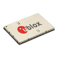
LTE modules
Brand:
Ublox
| Category:
Control Unit
| Size: 2 MB
Table of Contents
Preface
3
Contents
4
Table of Contents
4
1 System Description
7
Overview
7
Architecture
9
Internal Blocks
10
Pin-Out
11
TOBY-L1 Series Pin Assignment
11
MPCI-L1 Series Pin Assignment
13
Operating Modes
15
Supply Interfaces
17
Module Supply Input (VCC or 3.3Aux)
17
RTC Supply Output (V_BCKP)
21
Generic Digital Interfaces Supply Output (V_INT)
21
System Function Interfaces
22
Module Power-On
22
Module Power-Off
25
Module Reset
27
Antenna Interface
29
Antenna RF Interfaces (ANT1 / ANT2)
29
SIM Interface
32
SIM Card Interface
32
Data Communication Interfaces
32
Universal Serial Bus (USB)
32
General Purpose Input/Output (GPIO)
33
Mini Pcie Specific Signals (W_DISABLE#, LED_WWAN#)
34
Reserved Pins (RSVD)
34
Not Connected Pins (NC)
34
System Features
35
Network Indication
35
Power Saving
35
2 Design-In
36
Overview
36
Supply Interfaces
37
Module Supply (VCC or 3.3Aux)
37
RTC Supply Output (V_BCKP)
45
Digital I/O Interfaces Supply Output (V_INT)
45
System Functions Interfaces
46
Module Power-On (PWR_ON)
46
Module Reset (RESET_N and PERST#)
47
Antenna Interface
49
Antenna RF Interfaces (ANT1 / ANT2)
49
SIM Interface
55
Guidelines for SIM Circuit Design
55
Guidelines for SIM Layout Design
58
Data Communication Interfaces
59
Universal Serial Bus (USB)
59
General Purpose Input/Output (GPIO)
61
Mini Pcie Specific Signals (W_DISABLE#, LED_WWAN#)
62
Reserved Pins (RSVD)
64
Module Placement
64
TOBY-L1 Series Module Footprint and Paste Mask
65
MPCI-L1 Series Module Installation
66
Thermal Guidelines
68
ESD Guidelines
69
ESD Immunity Test Overview
69
ESD Immunity Test of TOBY-L1 and MPCI-L1 Series Reference Designs
69
ESD Application Circuits
70
Schematic for TOBY-L1 and MPCI-L1 Series Module Integration
72
Design-In Checklist
74
Schematic Checklist
74
Layout Checklist
74
Antenna Checklist
75
3 Handling and Soldering
76
Packaging, Shipping, Storage and Moisture Preconditioning
76
Handling
76
Soldering
77
Soldering Paste
77
Reflow Soldering
77
Optical Inspection
78
Cleaning
78
Repeated Reflow Soldering
78
Wave Soldering
79
Hand Soldering
79
Rework
79
Conformal Coating
79
Casting
79
Grounding Metal Covers
79
Use of Ultrasonic Processes
79
4 Approvals
80
Product Certification Approval Overview
80
Federal Communications Commission and Industry Canada Notice
81
Declaration of Conformity - United States Only
81
Modifications
81
5 Product Testing
83
U-Blox In-Series Production Test
83
Test Parameters for OEM Manufacturer
84
Go/No Go" Tests for Integrated Devices
84
RF Functional Tests
84
Connecting to Wireless Communication Test Set
86
Appendix
87
A Glossary
87
Related Documents
89
Revision History
89
Contact
90
Advertisement
Ublox TOBY-L1 series System Integration Manual (85 pages)
LTE Module
Brand:
Ublox
| Category:
Control Unit
| Size: 1 MB
Table of Contents
Preface
3
Contents
4
Table of Contents
4
1 System Description
7
Overview
7
Architecture
9
Internal Blocks
10
Pin-Out
11
Operating Modes
13
Supply Interfaces
15
Module Supply Input (VCC)
15
Supply Output (V_BCKP)
19
Supply Output (V_INT)
19
System Function Interfaces
20
Module Power-On
20
Module Power-Off
21
Module Reset
21
Antenna Interface
23
Antenna RF Interfaces (ANT1 / ANT2)
23
SIM Interface
23
SIM Card Interface
23
SIM Card Detection
23
Serial Interfaces
25
Usb
25
General Purpose Input/Output (GPIO)
27
Reserved Pins (RSVD)
27
System Features
28
Network Indication
28
TCP/IP and UDP/IP
29
Ftp
29
Http
29
Smtp
29
Firmware Upgrade over the Air (FOTA)
29
Power Saving
29
2 Design-In
31
Supply Interfaces
32
Module Supply (VCC)
32
Supply (V_BCKP)
40
Supply (V_INT)
41
System Functions Interfaces
42
Module Power-On (PWR_ON)
42
Module Reset (RESET_N)
43
Antenna Interface
45
Antenna RF Interface (ANT)
45
SIM Interface
50
Serial Interfaces
54
USB Interface
54
General Purpose Input/Output (GPIO)
56
Reserved Pins (RSVD)
57
Module Placement
57
Module Footprint and Paste Mask
58
Thermal Guidelines
60
ESD Guidelines
62
ESD Immunity Test Overview
62
ESD Immunity Test of U-Blox TOBY-L1 Series Reference Designs
62
ESD Application Circuits
63
Schematic for TOBY-L1 Series Module Integration
65
Design-In Checklist
67
Schematic Checklist
67
Layout Checklist
68
Antenna Checklist
68
3 Handling and Soldering
69
Packaging, Shipping, Storage and Moisture Preconditioning
69
Soldering
69
Soldering Paste
69
Reflow Soldering
69
Optical Inspection
71
Cleaning
71
Repeated Reflow Soldering
71
Wave Soldering
71
Hand Soldering
71
Rework
71
Conformal Coating
71
Casting
72
Grounding Metal Covers
72
Use of Ultrasonic Processes
72
4 Approvals
73
Product Certification Approval Overview
73
Federal Communications Commission and Industry Canada Notice
74
Safety Warnings Review the Structure
74
Declaration of Conformity - United States Only
74
Modifications
74
R&TTED and European Conformance CE Mark
76
5 Product Testing
77
U-Blox In-Series Production Test
77
Test Parameters for OEM Manufacturer
77
Go/No Go" Tests for Integrated Devices
78
Functional Tests Providing RF Operation
78
Appendix
80
A Glossary
81
Related Documents
83
Revision History
84
Contact
85
Advertisement
Related Products
Ublox TOBY-L100
Ublox TOBY-L110
UBlox TOBY-L2 series
Ublox TOBY-L280 Series
Ublox TOBY-L200-00S-01
Ublox TOBY-L200-03S-01
Ublox TOBY-L201-01S-00
Ublox TOBY-L201-02S-00
Ublox TOBY-L210-03S-01
Ublox TOBY-L210-62S-00
Ublox Categories
Control Unit
Motherboard
Computer Hardware
Wireless modules
Receiver
More Ublox Manuals
Login
Sign In
OR
Sign in with Facebook
Sign in with Google
Upload manual
Upload from disk
Upload from URL