Sign In
Upload
Manuals
Brands
Tsino Dynatron Manuals
Servo Drives
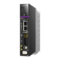
CoolDrive Smart 7 CDS7S
Tsino Dynatron CoolDrive Smart 7 CDS7S Manuals
Manuals and User Guides for Tsino Dynatron CoolDrive Smart 7 CDS7S. We have
1
Tsino Dynatron CoolDrive Smart 7 CDS7S manual available for free PDF download: User Manual
Tsino Dynatron CoolDrive Smart 7 CDS7S User Manual (285 pages)
EtherCAT interface
Brand:
Tsino Dynatron
| Category:
Servo Drives
| Size: 9 MB
Table of Contents
Wiring ---------------------------------------------------------------- 29
13
Table of Contents
13
Contents
13
Safety Instructions
13
Chapter 1 Preface
20
Overview
20
Chapters
20
Identification Description
21
Parameter Description
21
Data Plate
22
Model Identification
23
Specifications
24
Universal Specifications of (Standard) CDS7S
24
Technical Specifications of (Standard) CDS7S
26
Name of each Part of the Product
27
Standards and Certification
32
Chapter 2 Installation
33
Precautions
33
Inspection
34
Dimensions
35
T1 Model Dimensions
35
T2 Model Dimensions
36
T3 Model Dimensions
37
T4 Model Dimensions
38
Installation Direction and Space Requirements
39
Drive Installation Direction
39
Drive Installation Space Requirements
40
Chapter 3 Wiring
41
Precautions for Wiring
41
Safety Requirements
41
System Wiring Requirements
42
System Wiring Diagram
43
Power Supply Wiring
44
Ports and Functions
44
Power Supply Wiring Diagram
46
Precautions for Power Supply Wiring
49
Motor Wiring
50
Ports and Functions
50
Motor Wiring Diagram
53
Precautions for Motor Wiring
56
Ethercat Wiring
57
Ethercat Introduction
57
Ethercat Wiring Diagram
58
Port Symbols and Functions
58
Precautions for Ethercat Wiring
59
I/O Wiring
60
I/O Port Wiring Diagram
60
Port Symbols and Functions
60
STO Wiring
63
Port Symbols and Functions
63
STO Wiring Diagram
63
Chapter 4 Settings
65
Parameter Overview
65
Parameter Description
65
Parameter Setting Method
67
Parameters Return to Factory Settings
69
Drive Parameter Setting
71
Motor Parameters Settings
77
Encoder Parameters Settings
83
Position Control Settings
94
Velocity Control Setting
99
Torque Control Settings
103
Servo Enabling Setting
105
Setting of Stop Function
107
Ethercat Communication Setting
118
Cia402 Setting
119
Chapter 5 Running
121
Precautions before Running
121
Magnetic Pole Phase Angle Detection
121
Overview
121
Associated Parameters
122
How to Use
124
Trial Operation
128
Simple Velocity Mode
129
Programming Velocity Mode
131
Sine Wave Velocity Mode
134
Programming Torque Mode
135
Sine Wave Torque Mode
137
Point-To-Point Position Mode
138
Chapter 6 Operation Control Block Diagram
140
Overview
140
Position Mode Control Block Diagram
141
Velocity Mode Control Block Diagram
142
Torque Mode Control Block Diagram
143
Chapter 7 Adjustment
144
Overview of Servo Adjustment Function
144
Servo Adjustment Functions
144
Debugging Aid
145
Safety Instructions
146
Following Error Limit Setting
146
Position Limit Setting
146
Torque Limit Setting
146
Current Loop Setting
147
Associated Parameters
147
Overview
147
How to Use
148
System Parameter Identification
149
Associated Parameters
149
Overview
149
How to Use
150
Real-Time Identification & Real-Time Automatic Adjustment
154
Stiffness Mode Gain Adjustment
155
Associated Parameters
155
Overview
155
Adjustment
156
Invalid Parameters in the Stiffness Mode
156
How to Use
157
Index Name Unit Setting Range Default Value
157
Basic Mode Gain Adjustment
159
0X20C0 Inertia Ratio Setting % 0-5000
159
0X21C6 Regulator Basic Control Setting - 0X00000000-0X00000003
159
Associated Parameters
159
Overview
159
0X21C8 Position Loop Stiffness Gain1 0.1/S 0-65535
160
0X21C9 Position Loop Stiffness Gain 2 0.1/S 0-65535
160
0X21Ca Velocity Loop Stiffness Gain 1 0.1 Hz 0-65535
160
0X21Cb Velocity Loop Stiffness Gain 2 0.1 Hz 0-65535
160
How to Use
160
Index Name Unit Setting Range Default Value
160
Invalid Parameters in the Basic Mode
160
Torque Command Lowpass 0X2072 Hz 1-8000 8000 Filter Cutoff Frequency
160
Adaptive Gains Switching
162
Overview
162
0X21C8 Position Loop Stiffness Gain 1 0.1/S 0-65535
163
0X21C9 Position Loop Stiffness Gain 2 0.1/S 0-65535
163
0X21Ca Velocity Loop Stiffness Gain 1 0.1 Hz 0-65535
163
Associated Parameters
163
Position Loop Proportional Gain1
163
Position Loop Proportional Gain2
163
0X21Cb Velocity Loop Stiffness Gain
164
How to Use
164
Velocity Loop Proportional Gain2
164
Gain
166
Associated Parameters
166
How to Use
166
Overview
166
Feed-Forward
168
Overview
168
Velocity Feedforward
168
Acceleration Feedforward
169
Acceleration Feedforward Exceptions Correction
170
No Position Deviation Control
171
Lowpass Filters
172
Overview
172
Associated Parameters
173
How to Use
174
Overview
175
Vibration Suppression
175
Associated Parameters
176
How to Use
178
Compensation Functions
180
Friction Torque Compensation
180
Overview
180
Static Balance Torque Compensation
182
Load Disturbance Compensation
183
Static Position Disturbance Compensation
183
Chapter 8 Application Functions
185
Overview of Servo Application Functions
185
Electronic Gear Ratio
186
Associated Parameters
186
Overview
186
How to Use
187
Example of Electronic Gear Ratio Calculation
188
Quadrant Projection Suppression
189
Associated Parameters
189
Overview
189
How to Use
190
Infinite Position Mode
191
Overview
191
Associated Parameters
192
How to Use
193
Field Weakening Control Mode
199
Associated Parameters
199
Overview
199
How to Use
200
Position Comparison Output
201
Associated Parameters
201
Overview
201
How to Use
202
Touch Probe
204
Associated Parameters
204
Overview
204
How to Use
206
Dynamic Braking
210
Associated Parameters
210
Overview
210
How to Use
211
Digital Input and Output Function
213
Overview
213
Relevant Parameters
213
How to Use
215
Chapter 9 Monitoring
216
Panel Monitoring
216
Overview
216
Relevant Parameters
217
General Operations of Panel Monitoring
218
Panel Monitoring - Display Selection Menu
219
Panel Monitoring - Operating Data
220
Panel Monitoring - Communication State
222
Panel Monitoring - Device Information
222
Panel Monitoring - Current Alarm or Warning
224
Panel Monitoring - Historical Alarm
224
Debugging Software Monitoring
225
Debugging Software Monitoring - Device Information
225
Overview
225
Debug Software Monitoring - State Information
226
Debugging Software Monitoring - Operating Data
227
Debugging Software Monitoring - Alarm and Warning Information
231
Debugging Software Monitoring - IO State
233
Debugging Software Monitoring - Data Trace
234
Chapter 10 Maintenance
237
Maintenance Overview
237
Settings of Relevant Parameters
237
View Alarm and Warning Records
237
Alarm
245
Alarm List
245
Alarm Configuration
249
Troubleshooting
251
Warning
277
Warning List
277
Warning Handling Methods
278
Chapter 11 Safety Features
283
Overview
283
Definition of STO Function
283
Implementation of STO Function
284
Safety Function Risk Assessment
284
STO Action Sequence
285
STO Fault Detection Monitoring (EDM)
285
Advertisement
Advertisement
Related Products
Tsino Dynatron CoolDrive Series
Tsino Dynatron EtherCAT CoolDrive RC Series
Tsino Dynatron Categories
Servo Drives
More Tsino Dynatron Manuals
Login
Sign In
OR
Sign in with Facebook
Sign in with Google
Upload manual
Upload from disk
Upload from URL